EP0096889B2 - Schutzschalter mit Lichtbogenabsorption - Google Patents
Schutzschalter mit Lichtbogenabsorption Download PDFInfo
- Publication number
- EP0096889B2 EP0096889B2 EP83105827A EP83105827A EP0096889B2 EP 0096889 B2 EP0096889 B2 EP 0096889B2 EP 83105827 A EP83105827 A EP 83105827A EP 83105827 A EP83105827 A EP 83105827A EP 0096889 B2 EP0096889 B2 EP 0096889B2
- Authority
- EP
- European Patent Office
- Prior art keywords
- arc
- circuit breaker
- side walls
- light absorber
- contacts
- Prior art date
- Legal status (The legal status is an assumption and is not a legal conclusion. Google has not performed a legal analysis and makes no representation as to the accuracy of the status listed.)
- Expired - Lifetime
Links
Images


Classifications
-
- H—ELECTRICITY
- H01—ELECTRIC ELEMENTS
- H01H—ELECTRIC SWITCHES; RELAYS; SELECTORS; EMERGENCY PROTECTIVE DEVICES
- H01H9/00—Details of switching devices, not covered by groups H01H1/00 - H01H7/00
- H01H9/30—Means for extinguishing or preventing arc between current-carrying parts
Definitions
- the present invention relates to a circuit breaker according to the preamble of claim 1 as known for instance from FR-A-2 475 290.
- a circuit breaker usable also as a current limiter or electromagnetic switch is provided with a smallsized container in which the generation of an arc takes place when separating the contacts.
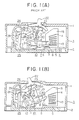
- a prior-art circuit breaker shall be described, whereby reference is made to Fig. 1A-1C showing a known circuit breaker in three different operating conditions.
- a cover 1 and a base 2 which together form a insulating container 3.
- a stationary contactor 4 which consists of a stationary conductor 5, provided at one end with a stationary contact 6 while the other end of the conductor 5 forms a terminal which is connected to an external conductor (not shown).
- a movable contactor 7 which consists of a movable conductor 8 and a movable contact 9 which is disposed oppositely to the contact 6.
- the circuit breaker is further provided with a movable contactor unit 10 and a movable element arm 11, which is attached to a crossbar 12 so that each pole of the circuit breaker can be opened or closed simultaneously.
- a arc extinguishing chamber 13 in which an arc extinguishing plate 14 is retained by a side plate 15.
- a toggle linkage 16 which has an upper link 17 and a lower link 18.
- One end of the upper link 17 is connected through a shaft 20 to a cradle 19 while at the other end is linked through a shaft 21 to one end of the lower link 18.
- the other end of the lower link 18 is connected to the arm 11 of the contactor unit 10.
- a tiltable operation handle 22 and an operation spring 23 are also arranged between the shaft 21 of the toggle linkage 16 and the handle 22.
- a thermal tripping mechanism 24 and an electromagnetic gripping mechanism 25 which serve to rotate a trip bar 28 counterclockwise via a bimetal 26 and a movable core 27.
- a latch which at one end is engaged with the bar 28 while the other end is engaged with the cradle 19.
- the injected arc energy eventually is transformed into thermal energy, which is dissipated by conduction out of the container. Transiently the gas temperature in within the container however rises which causes an abrupt increase of the gas pressure. This leads to a deterioration of the insulation of the circuit breaker, thereby increasing the quantity of arcing within the circuit breaker. Eventually this can produce an accident of the power source or a damage of the body of the circuit breaker.
- this object can be obtained in that on said conductors and surrounding said contacts there are fixed arc shields formed of a high resistance material having a resistivity higher than said conductors and being provided with arc moving paths for moving the arc in the desired direction, and that the side walls of the insulating container are provided with recesses formed corresponding to the loci of said contacts at opening and closing times. Further improvements of the invention can best obtained by providing the features as stated within the subclaims 2-6.
- the side walls absorb the light energy of the arc thereby suppressing a rise of the inner pressure of the container. Due to this fact there is no possibility for the container to be damaged at the breaking time while at the same time the quantity of arcing during the discharging is decreased. Accordingly, the present invention prevents the occurance of secondary accidents due to the short- circuits of the power source within or outside of the container, such secondary accidents occurring particularly when large currents are to be broken.
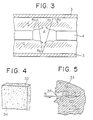
- Figure 2 is a view in which an arc A is produced between contactors 4 and 7.
- character T designates a flow of thermal energy which is dissipated from the arc A through the contactors
- character m flows of the energy of metallic particles which are released from an arc space
- character R flows of energy caused by a light which is irradiated from the arc space.
- the energy injected to the arc A is generally consumed by the flows T, m and R of the above three energies.
- the thermal energy T which is conducted to electrodes of these energies is extremely small, and most of the energies is carried away by the flows m and R.
- the consumption of the energy injected to the arc A can be analyzed as below.
- the above quantities are varied according to the shape of the contactors and the length of the arc.
- P K 10 to 20%
- Pth 5%
- P R 75 to 85%.
- the state that the arc A is enclosed in the container is shown in Figure 3.
- the space in the container 3 is filled with the metallic particles and becomes the state of high temperature.
- the above state is strong particularly in the gas space Q (the space Q designated by hatched lines in Figure 3) in the periphery of an arc positive column A.
- the light irradiated from the arc A is irradiated from the arc positive column A to the wall of the container 3, and is reflected on the wall.
- the reflected light is scattered, is passed again through the high temperature space in which the metallic particles are filled, and is again irradiated to the wall surface. Such coarses are repeated until the quantity of light becomes zero.
- the path of the light in the meantime is shown by Ra, Rb, Rc and Rc in Figure 3.
- the light irradiated from the arc includes wavelengths from far ultraviolet ray less than 2000 A (200 nm) to far infrared ray more than 1 ⁇ m in all wavelength range of continuous spectra and linear spectra.
- the wall surface of the general container merely has the light absorption capability only in the range of approx. 4000 A to 5500 A (400 nm to 550 nm) even if the surface is black, and partly absorbs in the other range, but almost reflects.
- the absorptions in the arc space and the peripheral high temperature gas space becomes as below.
- the quantity of light absorption by the gas space can be calculated as below.
- the formula (1) represents the quantity of absorption energy to special wavelength ⁇ .
- the Ae is the absorption probability to the special wavelength ⁇ , and is the function of the wavelength, gas temperature and type of the particles.
- the absorption coefficient becomes the largest value in the gas of the same state as a light source gas for irradiating the light (i.e., the type and the temperature of the particles are the same) in both the continuous spectra and the linear spectra according to the teaching of the quantum mechanics.
- the arc space and the peripheral gas space absorb the most light irradiated from the arc space.
- the quantity la of the absorption energy of the light is proportional to the length L of the light path. s shown in Figure 3, when the light from the arc space is reflected on the wall surface, the L in the formula (1) is increased by the times of the number of reflections of the light, and the quantity of the light energy absorbed at the high temperature section of the arc space is increased.
- a special material is used in such a manner that one or more types of fiber, net and highly porous material having more than 35% of porosity for effectively absorbing the light irradiated from the arc are selectively disposed at the special position for receiving the energy of the light of the arc in the container of the circuit breaker, thereby absorbing a great deal of the light in the container to lower the temperature of the gas space and to lower the pressure.
- the above-described fiber is selected from inorganic series, metals, composite materials, woven materials and non-woven fabric, and is necessary to have thermal strength since it is installed in the space which is exposed with the high temperature arc.
- the above-described net includes inorganic series, metals, composite materials, and further superposed materials in multilayers of fine metal gauze, woven strands to be selected. In the case of the net, it is also necessary to have thermal strength.
- the inorganic series adaptively include ceramics, carbon, asbestos, and the optimum metals include Fe, Cu, and may include plated Zn or Ni.
- the highly porous blank generally exists in the materials of the ranges of metals, inorganic series and organic series of the materials which have a number of fine holes in a solid structure, and are classified in the relationship between the material and the fine holes into one which contains as main body solid particles sintered and solidified at the contacting points therebetween, and the other which contains as main body holes in such a manner that the partition walls forming the holes are solid material.
- the blank means the material before being machined to a concrete shape, so-called "a material”.
- the blank can be classified into the blank in which the gaps among the particles exists as fine holes, the blank in which the gaps among the particles commonly exist in the fine holes of the holes in the particles, and the blank which contains foamable holes therein.
- the blanks are largely classified into the blank which has air permeability and water permeability, and the blank which has pores individually independent from each other without air permeability.
- the shape of the above fine holes is very complicated, and is largely classified into open holes and closed holes, the structures of which are expressed by the volume of the fine holes or porosity, the diameter of the fine holes and the distribution of the diameters of the fine holes and specific surface area.
- the true porosity is expressed by the void volume of the rate of the fine hole volume of all the open and closed holes contained in the porous blank with respect to the total volume (bulk volume) of the blank, i.e., percentage, which is measured by a substitution method and an absorption method with liquid or gas, but can be calculated as below as defined in the method of measuring the specific weight and the porosity of a refractory heat insulating brick of JISR 2614 (Japanese Industrial Standard, the Ceramic Industry No. 2614).
- the apparent porosity is expressed by the void volume of the rate of the volume of the open holes with respect to the total volume (bulk volume) of the blank, i.e., percentage, which can be calculated as below as defined by the method of measuring the apparent porosity, absorption rate and specific weight of a refractory heat insulating brick of JISR 2205 (Japanese Industrial Standard, the Ceramic Industry No. 2205).
- the apparent porosity may also be defined as an effective porosity.
- the diameter of the fine hole is obtained by the measured values of the volume of the fine holes and the specific surface area, and includes several A (Angstrom) to several mm from the size near the size of atom or ion to the boundary gap of particle group, which is generally defined as the mean value of the distribution.
- the diameter of the fine hole of the porous blank can be obtained by measuring the shape, size and distribution of the pore with a microscope, by a mercury press-fitting method. In order to accurately know the shape of composite pore and the state of the distribution of the pores, it is generally preferable to employ the microscope as a direct method.
- the measurement of the specific surface area is performed frequency by a BET method which obtains by utilizing adsorption isothermal lines in the respective temperatures of various adsorptive gases, and nitrogen gas is frequency used.
- Figure 4 is a perspective view showing an inorganic porous blank
- Figure 5 is an enlarged fragmentary sectional view of Figure 4.
- numeral 33 designates an inorganic porous blank
- numeral 34 open holes communicating with the surface of the blank. The diameters of the hole 34 are distributed in the range from several micron (pm) to several mm in various manner.
- the light is incident to the hole 34 when the light is incident to the blank 33 as designated by R in Figure 5
- the light is irradiated to the wall surface of the blank, is then reflected on the wall surface, is reflected in multiple ways in the hole, and is eventually absorbed by 100% to the wall surface.
- the light incident to the hole 34 is absorbed directly to the surface of the blank, and becomes heat in the hole.
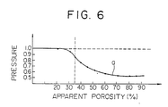
- Figure 6 shows characteristic curve diagram of the variation in the pressure in the model container in which the inorganic porous material is filled when the apparent porosity of the material is varied.
- the abscissa axis is the apparent porosity
- the ordinate axis expresses the pressure with the pressure when the porosity is 0 in the case that the inner wall of the container is formed of metal such as Cu, Fe or AI as 1 as the reference.
- an AgW contacts are installed in the predetermined gap of 10 mm in a sealed container of a cube having 10 cm of one side, an arc of sinusoidal wave current of 10 kA of the peak is produced for 8 msec, and the pressure in the container produced by the energy of the arc is measured.
- the inorganic porous material used in the above embodiment is porous porcelain which is prepared by forming and sintering the raw material of the porcelain of corodierite added with inflammable orfoaming agent thereto to porous material, which has 10 to 300 microns of the range of mean diameter of fine hole, 20, 30, 35, 40, 45, 50, 60, 70, 80 and 85% of apparent porosity of the porous blank, using various samples of 50 mm x 50 mm x 4 mm (thickness) disposed in the wall surface of the container to cover 50% of the surface area of the inner surface of the container.
- the deep holes cause more effective, and communicating pores are preferable.
- the fine holes of several thousands A to several 1000 f..lm of mean diameter, which slightly exceeds the above wavelengths, are adequate, and the highly porous material which exceeds 35% of the apparent porosity in the area of the holes occupying the surface is adapted for absorbing the light irradiated from the arc A.
- the effect can be particularly raised when the upper limit of the diameter of the fine holes is in the range less than 1000 ⁇ m and the specific surface area of the fine holes is larger.
- preferably absorbing characteristic can be obtained to the light irradiated from the arc in the material having 5 ⁇ m to 1 mm of mean diameter of the fine holes. It is also observed that the blank of glass having 5 or 20 ⁇ m preferably absorbs the light irradiated from the arc A.
- the pores of the inorganic porous material absorb the light energy, and effect to lower the pressure in the circuit breaker, which increases as the apparent porosity of the porous blank is increased, which is remarkably as the porosity becomes larger than 35%, and which is confirmed in the range up to 85%.
- the porosity is further increased, it is necessary to correspond by further increasing the thickness of the porous material.
- the porosity When the porosity is increased in the relationship between the apparent porosity and the mechanical strength of the porous blank, the blank becomes brittle, the thermal conductivity of the blank decreases, and the blank becomes readily fusible by the high heat. When the porosity is decreased, the effect of reducing the pressure in the circuit breaker is reduced. Accordingly, phe optimum apparent porosity of the porous blank in the practical use is in the range of 40 to 70% as highly porous material.
- Some prior-art circuit breaker uses the inorganic material, but its object is mainly to protect the organic material container against the arc A, and the necessary characteristics include the arc resistance, lifetime, thermal conduction, mechanical strength, insulation and carbonization remedy.
- the inorganic material which satisfies these necessities is composed of the material which has a trend of low porosity, and the object is different from the object of the present invention, and the apparent porosity of the prior-art material is approx. 20%.
- the highly porous blanks have inorganic, metallic and organic series, and the inorganic materials are particularly characterized as the insulator and the high melting point material. These two characteristics are adapted as the material to be installed in the container of the circuit breaker. In other words, since the blank is electrically insulating, which does not affect the adverse influence to the breakage, and since the blank has a high melting point, the blank is not molten nor produces gas, even if the blank is exposed with high temperature, and the blank is optimum as the pressure suppressing material.
- the inorganic porous materials have porous porcelain, refractory material, glass, and cured cement, all of which can be used to decrease the gas pressure in the circuit breaker.
- the porous materials of the organic series have problems in the heat resistance and gas production, the porous materials of the metal series have problems in the insulation and pressure resistance, and are respectively limited in the place to be used.
- numeral 5 designates a stationary conductor
- numeral 6 a stationary contact
- numeral 8 a movable conductor
- numeral 9 movable contact and numerals 35 and 35 side walls which form an arc light absorber, the material of which is formed of an inorganic porous material or a composite material of the inorganic porous material and an organic material having more than 35% of apparent porosity of the blank, which are arranged in the range for covering the entire side surfaces of the locus drawn by the contact 9 opening or closing, and are arranged to confront each other at both sides of the contacts 9 and 6.
- Arc shields which form part of the invention are not shown in Figs 9A, 9B and 9C.
- Arc shields which are formed of a high resistance material having a resistivity higherthan the material forming the conductors 5 and 6 are respectively fixed to the conductors 5 and 8 to surround the outer peripheries of the contacts 6 and 9.
- the high resistance material for forming the shields such as 101 in Fig. 7 comprises high resistance metals such as organic or inorganic nickel, iron, copper nickel, copper manganese, iron-carbon, iron nickel and iron chromium.
- the arc shields are readily formed, for example, by covering by plasma jet metallizing means the conductors 5 and 8 with the above high resistance material such as ceramics, or fixing the plate formed of the above high resistance material onto the conductors 5 and 8. According to the above covering means, the shields can not only be simply formed, but can be inexpensively formed and particularly suppressed in the increase in the weight at the side of the contactor 7. Accordingly, the inertial moment can be reduced, and the isolating speed of the contactor 7 is accelerated, thereby advantageously enhancing the arc voltage.
- Numerals 35 and 35 indicate side walls forming an arc light absorber, which is formed of a material selected from organic series, an inorganic series and from a composite material of one or more of fiber, net and porous material having more than 35% of apparent porosity and side walls are formed at both sides of the contacts 6 and 9 as shown, for example, in Figure 8B at the position of the portion for receiving the light of the arc 32 produced between the contacts 6 and 9.
- the other constituents are the same as the prior-art circuit breaker, and will be omitted for the description.
- the arc 32 is produced between the contacts 6 and 9 in the same manner as the prior-art circuit breaker, but since the arc shields are provided at the outer peripheries of the contacts 6 and 9, the arc 32 is throttled to the narrow space. Consequently, the sectional area of the arc 32 is extremely reduced as compared with the prior-art circuit breaker which does not have the shields, and the arc voltage is accordingly largely raised, thereby improving the current limiting performance.
- the magnitude of the flowing current is reduced, but when the arc voltage is raised, the instantaneous electric energy injected to the circuit (the production of the current and the arc voltage) is increased, and the pressure in the container is considerably increased, thereby apprehending the damage of the circuit breaker body or the increase in the quantity of discharging spark.
- the side walls 35 and 35 are provided at the position for receiving the light from the arc 32 in the above structure, the light energy of the arc 32 is absorbed by the light absorbing operations of the side walls 35 and 35, the arc gas pressure is thus suppressed, thereby reducing the internal pressure in the circuit breaker and performing sufficiently the function without disturbing the uses of the arc shields.
- Figure 8 shows a modified example of an arc shield.
- An arc moving path 104 which is formed of a groove formed toward a direction for isolating the contact 6 from the end 6a of a stationary contact 6 such as toward the arc moving direction, i.e., toward the arc extinguishing plate 14 is formed at the arc shield 103.
- the foot of the arc 32 moves on the arc moving path 104, and the arc 32 moves toward the plate 14.
- the arc 32 is readily contacted with the plate 14, thereby improving the breaking performance of the small current range.
- the side walls 35 and 35 employ an inorganic porous material which mainly contains magnesia or zirconia, the side walls 35 and 35 are not vitrified but are crystallined. Accordingly, the insulating resistance of the surfaces of the side walls 35 and 35 are not lowered during the arc generating period, thereby obtaining preferably breaking performance.
- the surfaces of the side walls 35 and 35 are heat treated and an organic material is suitably mixed with the inorganic porous material, the precipitation of powder from the side walls 35 and 35 due to the vibration and impact of the circuit breaker can be effectively prevented without disturbing the operation of lowering the internal pressure in the circuit breaker.
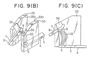
- Figure 9A shows the recesses formed on the side walls forming an arc light absorber.
- a pair of side walls 35 and 35 which have an area to cover all the locuses of the contacts 6 and 9 drawn when a pair of electric contacts 4 and 7 are opened and closed as shown in Figure 9B are disposed at both sides of the contactors 4 and 7.
- These side walls 35 and 35 are formed of an arc light absorber which is made of a composite material having one or more of fiber, net and a porous material having more than 35% of apparent porosity, and recesses 36 and 36 corresponding to the locuses of the contacts are respectively formed at the confronting surfaces 35a and 35a of the side walls 35 and 35, respectively.
- the arc 32 is produced as shown in Figure 9C when the contacts 6 and 9 are opened, but since the side walls 35 and 35 which are formed of the arc light absorber formed of the above-described special material are provided, the light energy from the arc 32 is absorbed by the side walls 35 and 35. Particularly in this case, the side walls 35 and 35 formed of the arc light absorber are disposed at the nearest position to the position for producing the arc, and the stereoscopic angle for receiving the energy of the light irradiated from the arc 32 becomes very large at the position approaching the arc, even if at both sides of the contacts 6 and 9, and the above-described effects and advantages and hence the operation of absorbing the energy of the light can be accordingly very efficiently performed.
- the quantity of arc discharge spark at the breaking time can be reduced, and particularly the secondary fire accident due to the power supply shortcircuit in and out the container 3 which tends to occur at the time of breaking the large current can be prevented in advance.
- the internal pressure is decreased, the temperature of the arc 32 is decreased, and since the arc 32 is interposed between the side walls 35 and 35 formed of the arc light absorber from both side surfaces, the decreases in the insulating resistance between the power supply and the load caused by the melting and evaporating of the metal and the insulator in the vicinity of the arc 32 and between the phases can be prevented, thereby securing the safety.
- the recesses 36 and 36 are fored on the confronting surfaces 35a and 35a of the side walls 35 and 35, respectively, corresponding to the locuses of the contacts, the local burnout of the side walls 35 and 35 confronting the positive column of the arc 32 at the highest temperature can be prevented, thereby sufficiently remedying against the frequent opening and closing operations and frequent breaking operations of the circuit breaker and maintaining the operations of the side walls 35 and 35 for a long period of time.
Landscapes
- Arc-Extinguishing Devices That Are Switches (AREA)
Claims (6)
Applications Claiming Priority (6)
| Application Number | Priority Date | Filing Date | Title |
|---|---|---|---|
| JP9060482U JPS58192440U (ja) | 1982-06-15 | 1982-06-15 | 開閉器 |
| JP90604/82U | 1982-06-15 | ||
| JP186304/82 | 1982-10-22 | ||
| JP18630482A JPS5975515A (ja) | 1982-10-22 | 1982-10-22 | 開閉器 |
| JP16539082U JPS5969467U (ja) | 1982-10-29 | 1982-10-29 | 開閉器 |
| JP165390/82U | 1982-10-29 |
Publications (4)
| Publication Number | Publication Date |
|---|---|
| EP0096889A2 EP0096889A2 (de) | 1983-12-28 |
| EP0096889A3 EP0096889A3 (en) | 1986-11-20 |
| EP0096889B1 EP0096889B1 (de) | 1988-09-07 |
| EP0096889B2 true EP0096889B2 (de) | 1993-04-14 |
Family
ID=27306489
Family Applications (1)
| Application Number | Title | Priority Date | Filing Date |
|---|---|---|---|
| EP83105827A Expired - Lifetime EP0096889B2 (de) | 1982-06-15 | 1983-06-14 | Schutzschalter mit Lichtbogenabsorption |
Country Status (3)
| Country | Link |
|---|---|
| US (1) | US4516003A (de) |
| EP (1) | EP0096889B2 (de) |
| DE (1) | DE3377957D1 (de) |
Families Citing this family (6)
| Publication number | Priority date | Publication date | Assignee | Title |
|---|---|---|---|---|
| JP3099685B2 (ja) * | 1995-06-20 | 2000-10-16 | 富士電機株式会社 | 回路遮断器 |
| US7796369B2 (en) * | 2006-05-01 | 2010-09-14 | Siemens Industry, Inc. | Devices, systems, and methods for shunting a circuit breaker |
| FR2969366B1 (fr) * | 2010-12-20 | 2013-03-01 | Schneider Electric Ind Sas | Dispositif de coupure a ecran de coupure d'arc |
| US8993916B2 (en) | 2012-12-07 | 2015-03-31 | General Electric Company | Variable venting and damping arc mitigation assemblies and methods of assembly |
| DE102014001730A1 (de) * | 2014-02-08 | 2015-08-13 | Ellenberger & Poensgen Gmbh | Schaltsystem |
| US10636607B2 (en) * | 2017-12-27 | 2020-04-28 | Eaton Intelligent Power Limited | High voltage compact fused disconnect switch device with bi-directional magnetic arc deflection assembly |
Family Cites Families (15)
| Publication number | Priority date | Publication date | Assignee | Title |
|---|---|---|---|---|
| US2864919A (en) * | 1955-05-11 | 1958-12-16 | Ite Circuit Breaker Ltd | Ceramic arcing plate material |
| DE1189607B (de) * | 1961-11-27 | 1965-03-25 | Merlin Gerin | Daempfungswiderstand fuer elektrische Schalter |
| CH556603A (de) * | 1973-03-20 | 1974-11-29 | Bbc Brown Boveri & Cie | In einer schaltkammer eines elektrischen schalters, insbesondere eines sf6-druckgasschalters, angeordneter bauteil aus unter der einwirkung der lichtbogenwaerme gasabgebendem werkstoff. |
| JPS5457453A (en) * | 1977-10-17 | 1979-05-09 | Mitsubishi Electric Corp | Manufacture of partly soft metallic spring sheet |
| JPS5546487A (en) * | 1978-09-30 | 1980-04-01 | Matsushita Electric Works Ltd | Arc extinguishing device |
| FR2475290A1 (fr) * | 1980-01-31 | 1981-08-07 | Merlin Gerin | Chambre de coupure de disjoncteurs basse tension a joues composites de guidage de l'arc |
| JPS56112842A (en) * | 1980-02-07 | 1981-09-05 | Hitachi Ltd | Field device for rotary electric machine |
| JPS56143635A (en) * | 1980-04-07 | 1981-11-09 | Sumitomo Electric Industries | Arc shoot |
| JPS578118A (en) * | 1980-06-20 | 1982-01-16 | Mitsubishi Petrochem Co Ltd | Biaxially oriented polypropylene film and manufacture thereof |
| US4297290A (en) * | 1980-07-17 | 1981-10-27 | Ici Americas Inc. | Process for preparing sorbitan esters |
| JPS5769605A (en) * | 1980-10-20 | 1982-04-28 | Tokyo Shibaura Electric Co | Porous ceramics |
| JPS5812221A (ja) * | 1981-07-15 | 1983-01-24 | 三菱電機株式会社 | 消弧室用焼成部材 |
| EP0098308B1 (de) * | 1982-01-14 | 1988-08-03 | Mitsubishi Denki Kabushiki Kaisha | Schalter |
| EP0092184B1 (de) * | 1982-04-15 | 1988-07-20 | Mitsubishi Denki Kabushiki Kaisha | Schutzschalter mit Lichtbogenabsorption |
| US4516002A (en) * | 1982-04-15 | 1985-05-07 | Mitsubishi Denki Kabushiki Kaisha | Circuit breaker with arc light absorber |
-
1983
- 1983-04-14 US US06/485,582 patent/US4516003A/en not_active Expired - Fee Related
- 1983-06-14 DE DE8383105827T patent/DE3377957D1/de not_active Expired
- 1983-06-14 EP EP83105827A patent/EP0096889B2/de not_active Expired - Lifetime
Also Published As
| Publication number | Publication date |
|---|---|
| EP0096889A3 (en) | 1986-11-20 |
| US4516003A (en) | 1985-05-07 |
| EP0096889A2 (de) | 1983-12-28 |
| EP0096889B1 (de) | 1988-09-07 |
| DE3377957D1 (en) | 1988-10-13 |
Similar Documents
| Publication | Publication Date | Title |
|---|---|---|
| US4575598A (en) | Circuit breaker | |
| EP0096889B2 (de) | Schutzschalter mit Lichtbogenabsorption | |
| EP0092184B1 (de) | Schutzschalter mit Lichtbogenabsorption | |
| EP0092189B1 (de) | Schutzschalter mit Lichtbogenabsorption | |
| JPH0132673Y2 (de) | ||
| JPH0335769B2 (de) | ||
| KR890001334Y1 (ko) | 개 폐 기 | |
| KR870002152B1 (ko) | 호광(弧光) 흡수체를 부설한 회로차단기 | |
| JPH029480Y2 (de) | ||
| JPS58181238A (ja) | 開閉器 | |
| JPS5979933A (ja) | 開閉器 | |
| JPS58181247A (ja) | 開閉器 | |
| JPS58181235A (ja) | 開閉器 | |
| JPS58181241A (ja) | 開閉器 | |
| JPS58181229A (ja) | 開閉器 | |
| JPS58181232A (ja) | 開閉器 | |
| JPS58181228A (ja) | 開閉器 | |
| JPS5935338A (ja) | 開閉器 | |
| JPS58181234A (ja) | 開閉器 | |
| JPH0451926B2 (de) | ||
| JPS58181240A (ja) | 開閉器 | |
| JPS58181233A (ja) | 開閉器 | |
| JPS58181230A (ja) | 開閉器 | |
| JPH03734B2 (de) | ||
| JPS58181231A (ja) | 開閉器 |
Legal Events
| Date | Code | Title | Description |
|---|---|---|---|
| PUAI | Public reference made under article 153(3) epc to a published international application that has entered the european phase |
Free format text: ORIGINAL CODE: 0009012 |
|
| AK | Designated contracting states |
Designated state(s): CH DE FR GB IT LI |
|
| PUAL | Search report despatched |
Free format text: ORIGINAL CODE: 0009013 |
|
| AK | Designated contracting states |
Kind code of ref document: A3 Designated state(s): CH DE FR GB IT LI |
|
| 17P | Request for examination filed |
Effective date: 19861113 |
|
| 17Q | First examination report despatched |
Effective date: 19870323 |
|
| GRAA | (expected) grant |
Free format text: ORIGINAL CODE: 0009210 |
|
| AK | Designated contracting states |
Kind code of ref document: B1 Designated state(s): CH DE FR GB IT LI |
|
| ITF | It: translation for a ep patent filed | ||
| REF | Corresponds to: |
Ref document number: 3377957 Country of ref document: DE Date of ref document: 19881013 |
|
| ET | Fr: translation filed | ||
| PLBI | Opposition filed |
Free format text: ORIGINAL CODE: 0009260 |
|
| 26 | Opposition filed |
Opponent name: SIEMENS AKTIENGESELLSCHAFT, BERLIN UND MUENCHEN Effective date: 19890606 |
|
| ITTA | It: last paid annual fee | ||
| PGFP | Annual fee paid to national office [announced via postgrant information from national office to epo] |
Ref country code: GB Payment date: 19920505 Year of fee payment: 10 |
|
| PGFP | Annual fee paid to national office [announced via postgrant information from national office to epo] |
Ref country code: CH Payment date: 19920615 Year of fee payment: 10 |
|
| PUAH | Patent maintained in amended form |
Free format text: ORIGINAL CODE: 0009272 |
|
| STAA | Information on the status of an ep patent application or granted ep patent |
Free format text: STATUS: PATENT MAINTAINED AS AMENDED |
|
| 27A | Patent maintained in amended form |
Effective date: 19930414 |
|
| AK | Designated contracting states |
Kind code of ref document: B2 Designated state(s): CH DE FR GB IT LI |
|
| ITF | It: translation for a ep patent filed | ||
| REG | Reference to a national code |
Ref country code: CH Ref legal event code: AEN |
|
| PGFP | Annual fee paid to national office [announced via postgrant information from national office to epo] |
Ref country code: FR Payment date: 19930609 Year of fee payment: 11 |
|
| PG25 | Lapsed in a contracting state [announced via postgrant information from national office to epo] |
Ref country code: GB Effective date: 19930614 |
|
| PGFP | Annual fee paid to national office [announced via postgrant information from national office to epo] |
Ref country code: DE Payment date: 19930623 Year of fee payment: 11 |
|
| PG25 | Lapsed in a contracting state [announced via postgrant information from national office to epo] |
Ref country code: LI Effective date: 19930630 Ref country code: CH Effective date: 19930630 |
|
| ET3 | Fr: translation filed ** decision concerning opposition | ||
| GBPC | Gb: european patent ceased through non-payment of renewal fee |
Effective date: 19930614 |
|
| REG | Reference to a national code |
Ref country code: CH Ref legal event code: PL |
|
| PG25 | Lapsed in a contracting state [announced via postgrant information from national office to epo] |
Ref country code: FR Effective date: 19950228 |
|
| PG25 | Lapsed in a contracting state [announced via postgrant information from national office to epo] |
Ref country code: DE Effective date: 19950301 |
|
| REG | Reference to a national code |
Ref country code: FR Ref legal event code: ST |