EP0096645B1 - Dispositif d'étanchéité pour robinet à tournant sphérique - Google Patents
Dispositif d'étanchéité pour robinet à tournant sphérique Download PDFInfo
- Publication number
- EP0096645B1 EP0096645B1 EP83420095A EP83420095A EP0096645B1 EP 0096645 B1 EP0096645 B1 EP 0096645B1 EP 83420095 A EP83420095 A EP 83420095A EP 83420095 A EP83420095 A EP 83420095A EP 0096645 B1 EP0096645 B1 EP 0096645B1
- Authority
- EP
- European Patent Office
- Prior art keywords
- ring
- annular
- ball
- outer ring
- deformable means
- Prior art date
- Legal status (The legal status is an assumption and is not a legal conclusion. Google has not performed a legal analysis and makes no representation as to the accuracy of the status listed.)
- Expired
Links
- 238000007789 sealing Methods 0.000 title claims description 16
- 239000012530 fluid Substances 0.000 claims description 15
- 230000002706 hydrostatic effect Effects 0.000 claims description 9
- 239000000463 material Substances 0.000 claims description 7
- 239000002184 metal Substances 0.000 claims description 6
- 238000006073 displacement reaction Methods 0.000 claims description 4
- 230000002093 peripheral effect Effects 0.000 claims description 2
- 239000013536 elastomeric material Substances 0.000 claims 1
- 229920000034 Plastomer Polymers 0.000 description 5
- 238000010276 construction Methods 0.000 description 4
- 230000000694 effects Effects 0.000 description 4
- 229920001971 elastomer Polymers 0.000 description 4
- 239000000806 elastomer Substances 0.000 description 4
- 229920002994 synthetic fiber Polymers 0.000 description 3
- 239000011324 bead Substances 0.000 description 2
- 230000006378 damage Effects 0.000 description 2
- 238000001125 extrusion Methods 0.000 description 2
- 230000006835 compression Effects 0.000 description 1
- 238000007906 compression Methods 0.000 description 1
- 239000007769 metal material Substances 0.000 description 1
- 239000003208 petroleum Substances 0.000 description 1
- 238000007747 plating Methods 0.000 description 1
Images

Classifications
-
- F—MECHANICAL ENGINEERING; LIGHTING; HEATING; WEAPONS; BLASTING
- F16—ENGINEERING ELEMENTS AND UNITS; GENERAL MEASURES FOR PRODUCING AND MAINTAINING EFFECTIVE FUNCTIONING OF MACHINES OR INSTALLATIONS; THERMAL INSULATION IN GENERAL
- F16K—VALVES; TAPS; COCKS; ACTUATING-FLOATS; DEVICES FOR VENTING OR AERATING
- F16K5/00—Plug valves; Taps or cocks comprising only cut-off apparatus having at least one of the sealing faces shaped as a more or less complete surface of a solid of revolution, the opening and closing movement being predominantly rotary
- F16K5/06—Plug valves; Taps or cocks comprising only cut-off apparatus having at least one of the sealing faces shaped as a more or less complete surface of a solid of revolution, the opening and closing movement being predominantly rotary with plugs having spherical surfaces; Packings therefor
- F16K5/0663—Packings
- F16K5/0673—Composite packings
-
- F—MECHANICAL ENGINEERING; LIGHTING; HEATING; WEAPONS; BLASTING
- F16—ENGINEERING ELEMENTS AND UNITS; GENERAL MEASURES FOR PRODUCING AND MAINTAINING EFFECTIVE FUNCTIONING OF MACHINES OR INSTALLATIONS; THERMAL INSULATION IN GENERAL
- F16K—VALVES; TAPS; COCKS; ACTUATING-FLOATS; DEVICES FOR VENTING OR AERATING
- F16K5/00—Plug valves; Taps or cocks comprising only cut-off apparatus having at least one of the sealing faces shaped as a more or less complete surface of a solid of revolution, the opening and closing movement being predominantly rotary
- F16K5/08—Details
- F16K5/14—Special arrangements for separating the sealing faces or for pressing them together
- F16K5/20—Special arrangements for separating the sealing faces or for pressing them together for plugs with spherical surfaces
- F16K5/205—Sealing effected by the flowing medium
Definitions
- the invention relates to a sealing device for ball valves and connection flanges.
- Such a device intended to ensure the seal between the body and the turn, is associated with each of the channels provided in the body for the passage of the fluid and comprises means coming into sealing contact with the turn.
- the invention relates more specifically to devices in which an annular seal is pressed against the turn by the hydrostatic pressure of the fluid.
- the seal is part of a rigid assembly displaceable by pressure and having the general shape of an annular piston disposed around the corresponding channel.
- This bulky construction is difficult to use on taps of small section.
- the displacements of this rigid assembly are affected by friction problems, so that the force, with which the seal is pressed against the turn, is not really proportional to the hydrostatic pressure and that leaks may occur.
- a device of this type which corresponds to the preamble of claim 1, is described in patent US-A-2,916,254.
- the present invention aims to provide a sealing device, of simple construction, which is also adaptable to ball valves of small dimension and which ensures a perfect seal, whatever the pressure. This object is achieved by the invention, as characterized in claim 1.
- the deformable means reacting to hydrostatic pressure are made of elastomer and are in contact and pressed against the annular seal, made of plastomer and with which it forms a continuous sealing assembly, while the annular housing is delimited between two rings, respectively inner and outer, whose free bevelled ends come close to the turn, but without contact with it.
- the means reacting to the pressure When at least one of the tap channels is subjected to the hydrostatic pressure of the fluid, the means reacting to the pressure are deformed under the influence of this pressure and communicate to the annular seal an effort which, proportional to this pressure, tends to press it further against the turn.
- the annular seal and the means reacting to the pressure form a continuous and deformable sealing assembly, of small bulk.
- the two rings facilitate the construction of the valve body and, when at least one of them is made of metal, ensure a residual seal in the event of destruction of the seals by fire.
- the outer ring comprises, near the bottom of the annular housing, a sloping face forming a support chamfer for the deformable means and is mounted in the body with the possibility of longitudinal displacement.
- the deformable means When the deformable means are deformed by pressure, they are based on the aforementioned chamfer and communally to the outer ring, an effort tending to keep it away from the turning point. This arrangement avoids that, under the effect of pressure, the outer ring also come into contact with the turn, which would increase the tightening of the latter and, consequently, the torque required to operate it.
- this tap is composed of a body (2) associated with a cap (3) and a turn (4).
- This turn is integral with two shaft bottles, respectively, (5) mounted free in rotation in the body, and (6) mounted free in rotation in the cap.
- the end of the shaft (6) passes through the cap and comprises, at its end, a drive edge (7) called to cooperate with an operating member.
- connection flanges (8) are added, each comprising an internal channel (9) for the passage to the fluid.
- the turn (4) also includes an internal channel (10) for the monk capable of coming into the extension of the channels (9) of the two aforementioned flanges.
- the seal between the body and the turn is ensured by a device generally designated by (12).
- this sealing device is composed of an annular seal (13) arranged with a ring (14) of elastically deformable material in an annular housing formed around the channel corresponding for the passage of the fluid.
- the annular seal (13) is made of plastic material of the plastomer type, while the deformable ring (14) is made of a plastic material of the elastomer type.
- the annular housing containing the seal (13) and the ring (14) is itself delimited by a ring inner (16) and by an outer ring (17).
- the inner ring (16) is made of metal and, in this embodiment, is fitted into the connection flange (8).
- the outer ring (17), which is made of plastomer-type synthetic material, is housed in a bore (18) of the body, that is to say can slide relative to this body.
- the inner ring (16) guides the annular seal (13) and opposes its possible extrusion by pressure. To this end, the play existing between its free end (16a) and the turn (4) is very reduced.
- This ring (16) also includes one or more channels (19) putting the fluid passage channel (9) into communication with the annular housing (15). This channel is arranged so as to communicate with the part of the annular housing (15) containing the deformable ring (14) which, by the way, has a cross section greater than the cross section of the annular seal (13).
- the outer ring (17) performs the same functions as the inner one (16). It also comprises, at its free end, a chamfer (17a) delimiting a conical bearing capable of coming into sliding contact with the turn (4).
- the seal is ensured by the difference in pressures prevailing between the fluid inlet orifice and the interior functional volume of the valve which does not come out when the fluid passes, that is to say by difference of pressure on either side of the continuous and deformable sealing assembly composed of the annular seal (13) and the deformable ring (14).
- the channels (9) for the passage of the fluid is subjected to the hydrostatic pressure of the fluid, this is directed by the channels (19) directly against the deformable ring (14).
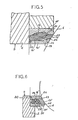
- the ring deforms, as shown in Figure 3. This deformation increases its support against the bottom of the annular housing (15), but also and, above all, against the annular seal (13) which is thus pressed against the turn (14) with a force which is proportional to the hydrostatic pressure of the fluid arriving at the tap.
- this ring (17) comprises, in its rear part and near the bottom of the annular housing, a sloping face (17b ) support for the deformable ring (14).
- a sloping face (17b ) support for the deformable ring (14) In this way, when the ring is deformed, and at the same time as it tends to push the annular seal (13) against the turn, it communicates to the ring (17) a force of opposite direction tending to move this ring away from the turn (4).
- the deformable ring (14) has a peripheral bead (14a) which is received in a groove (20) of the ring (17).
- This groove has two lateral faces inclined in the direction of the bottom of the annular housing (15), namely the sloping face (17b) mentioned above, and a face (17c) which, in this embodiment, is less inclined than the previous one.
- the width of this groove is determined so that the bead (14a) can in no case come into contact with the face (17c), so that, under the effect of the deformation of this ring (14), the outer ring (17) is exclusively subjected to a force tending to move it away from the turn (4).
- the deformable ring (14) has anterior (14b) and posterior (14c) faces which are concave in order to facilitate its deformation under the effect of hydrostatic pressure.
- the seal on the shaft ends (5) and (6) of the turn is obtained by deformation of a lip seal (23) bearing against a centering ring (22), which reduces the friction of the turn and therefore facilitates its operation.
- This sealing device also meets the fire safety rules, since in the event of fire and destruction of the seal (13), the deformable ring (14) and the outer ring (17), the inner metal ring (18), as well as the outer ring (17), coming very close to the turn (4) and without contact with it, ensures a residual seal under the practical conditions of "fire-safe" sealing of petroleum applications.
- the embodiment of Figure 5 differs from the previous ones in that the inner ring (18,) is mounted free in translation in the body (2) in the same way as the outer ring (17 ').
- this inner ring (18 ') is linked in translation to the annular seal (13').
- This connection. is provided by a flange (23) of the ring (16 ') capable of cooperating with a flange (24) of the seal (13').
- the deformable ring (14 ') has, at rest, the shape of a ring with rectangular cross section.
- This ring is placed in the housing (15) formed between the rings (18 ') and (17') and delimited transversely by a diametrical wall of the body (2) and by an inclined face (25) of the joint (13 ') . Thanks to this arrangement, the deformable ring (14 ') is supported, by two of its opposite rounded angles, respectively on the diametrical face of the body (2) and on the face (25) of the annular seal (13,).
- the ring (14 ') is made of a synthetic material of the elastomer type, while the annular seal (13') is made of a synthetic material of the plastomer type and that the two guide rings (16 ') and (17') are made of rigid and non-deformable materials, of metallic or synthetic type.
- the inner ring (16 ') has a channel (19) communicating the housing (15) with the fluid passage channel.
- the outer ring (17 ') is provided with a channel (26) allowing communication of the housing (15) with the inner part of the valve.
- the inner ring (16 ') has a groove for a square section seal (27) held in place by the deformable ring (14') and constituting an anti-extrusion ring.
- the sealing device forms a practically one-piece assembly which can be easily manipulated and placed in the body of the valve.
- the deformable ring consists of at least two O-rings (28) which, even in the absence of pressure, are in sealing contact with each other and with the faces annular housing (15).
- the device is similar to that of FIG. 5 and provides excellent results.
- the deformations of the sealing means are carried out only in a deformable medium, of the elastomer or plastomer type, and are not sensitive to the phenomena of hydraulic plating affecting metal surfaces, as is the case in the usual devices.
Landscapes
- Engineering & Computer Science (AREA)
- General Engineering & Computer Science (AREA)
- Mechanical Engineering (AREA)
- Sealing Devices (AREA)
- Gasket Seals (AREA)
- Taps Or Cocks (AREA)
Applications Claiming Priority (2)
| Application Number | Priority Date | Filing Date | Title |
|---|---|---|---|
| FR8210085 | 1982-06-07 | ||
| FR8210085A FR2528144A1 (fr) | 1982-06-07 | 1982-06-07 | Dispositif d'etancheite pour robinet a tournant spherique |
Publications (2)
| Publication Number | Publication Date |
|---|---|
| EP0096645A1 EP0096645A1 (fr) | 1983-12-21 |
| EP0096645B1 true EP0096645B1 (fr) | 1986-10-15 |
Family
ID=9274834
Family Applications (1)
| Application Number | Title | Priority Date | Filing Date |
|---|---|---|---|
| EP83420095A Expired EP0096645B1 (fr) | 1982-06-07 | 1983-06-07 | Dispositif d'étanchéité pour robinet à tournant sphérique |
Country Status (4)
| Country | Link |
|---|---|
| US (1) | US4511150A (enExample) |
| EP (1) | EP0096645B1 (enExample) |
| DE (1) | DE3367011D1 (enExample) |
| FR (1) | FR2528144A1 (enExample) |
Families Citing this family (35)
| Publication number | Priority date | Publication date | Assignee | Title |
|---|---|---|---|---|
| JPS59194175A (ja) * | 1983-04-12 | 1984-11-02 | Kobe Steel Ltd | ボ−ルバルブのシ−ル機構 |
| DK158016C (da) * | 1984-07-11 | 1990-08-13 | Broen Armatur As | Fremgangsmaade til montering af en kugleventil |
| US4796858A (en) * | 1987-10-01 | 1989-01-10 | Halliburton Company | Dual seal valve |
| US5299701A (en) * | 1989-02-03 | 1994-04-05 | Senetics, Inc. | Indicator cap |
| US5205536A (en) * | 1992-09-24 | 1993-04-27 | Newport News Shipbuilding And Dry Dock Company | Top entry, trunnion-type ball valve |
| US6142339A (en) * | 1998-01-16 | 2000-11-07 | 1263152 Ontario Inc. | Aerosol dispensing device |
| DE69918267T2 (de) | 1998-01-16 | 2005-07-28 | 1263152 Ontario Inc., London | Anzeigevorrichtung zur verwendung mit einer abgabevorrichtung |
| US6336453B1 (en) | 1999-04-30 | 2002-01-08 | Trudell Medical International | Indicating device for aerosol container |
| US6082358A (en) * | 1998-05-05 | 2000-07-04 | 1263152 Ontario Inc. | Indicating device for aerosol container |
| US6729330B2 (en) | 1998-05-05 | 2004-05-04 | Trudell Medical International | Indicating device for aerosol container |
| US6745760B2 (en) | 2001-05-15 | 2004-06-08 | Trudell Medical International | Medicament applicator |
| ITBS20010071U1 (it) * | 2001-07-27 | 2003-01-27 | Enolgas Bonomi S P A | Guarnizione toroidale composita per valvole a sfera |
| US7004164B2 (en) * | 2002-03-21 | 2006-02-28 | Trudell Medical International | Indicating device for aerosol container |
| US7621273B2 (en) | 2003-10-28 | 2009-11-24 | Trudell Medical International | Indicating device with warning dosage indicator |
| US7100530B2 (en) * | 2003-12-15 | 2006-09-05 | Trudell Medical International, Inc. | Dose indicating device |
| US7543582B2 (en) * | 2004-09-20 | 2009-06-09 | Trudell Medical International | Dose indicating device with display elements attached to container |
| US7886934B2 (en) * | 2005-01-20 | 2011-02-15 | Trudell Medical International | Dispensing device |
| US7544293B2 (en) | 2005-09-26 | 2009-06-09 | Semba Inc. | Valve and process for interrupted continuous flow chromatography |
| RU2302574C1 (ru) * | 2005-11-22 | 2007-07-10 | Общество с ограниченной ответственностью "Завод "Газпроммаш" | Шаровой кран |
| US8141550B2 (en) | 2006-08-01 | 2012-03-27 | Trudell Medical International | Dispensing device |
| US8807164B2 (en) * | 2006-08-30 | 2014-08-19 | Semba Biosciences, Inc. | Valve module and methods for simulated moving bed chromatography |
| US7790040B2 (en) | 2006-08-30 | 2010-09-07 | Semba Biosciences, Inc. | Continuous isocratic affinity chromatography |
| US8082873B2 (en) * | 2008-05-05 | 2011-12-27 | Trudell Medical International | Drive mechanism for an indicating device |
| US8181591B1 (en) | 2008-05-23 | 2012-05-22 | Trudell Medical International | Domed actuator for indicating device |
| US8196603B2 (en) | 2008-08-20 | 2012-06-12 | Semba Biosciences, Inc. | Valve block assembly |
| ES2402241T3 (es) | 2008-10-22 | 2013-04-30 | Trudell Medical International | Sistema de suministro de aerosol modular |
| DE102009006904A1 (de) * | 2009-01-30 | 2010-08-12 | Audi Ag | Dichtungsanordnung für einen Drehschieber |
| US20120153206A1 (en) * | 2010-12-16 | 2012-06-21 | Zipson Steel Industrial Co., Ltd. | Ball Valve |
| WO2012158724A1 (en) * | 2011-05-16 | 2012-11-22 | Seaboard International Inc. | Valve seat and valve |
| US8955541B2 (en) * | 2012-12-21 | 2015-02-17 | Fisher Regulators (Shanghai) Co., Ltd. | Disc assembly with branch hole for fluid flow control device |
| GB201319224D0 (en) * | 2013-10-31 | 2013-12-18 | Clyde Process Ltd | Powder isolating valve |
| US11162595B2 (en) * | 2016-02-18 | 2021-11-02 | Gasket International S.R.L. | Sealing assembly for ball valves and ball valve comprising such a sealing assembly |
| CN111201392A (zh) * | 2017-08-10 | 2020-05-26 | 嘉士凯国际有限责任公司 | 用于球阀的密封组件和包括这种密封组件的球阀 |
| CN107631051A (zh) * | 2017-10-17 | 2018-01-26 | 兰州高压阀门有限公司 | 一种用于低温球阀阀座的双重密封结构 |
| EP3940275B1 (en) * | 2020-07-17 | 2024-09-04 | Goodrich Corporation | Valve assembly |
Family Cites Families (13)
| Publication number | Priority date | Publication date | Assignee | Title |
|---|---|---|---|---|
| DE520188C (de) * | 1926-03-16 | 1931-03-09 | Charmilles Sa Ateliers | Abdichtungsvorrichtung fuer Druckwasserleitungsschieber |
| US2653004A (en) * | 1942-10-07 | 1953-09-22 | Von Roll Ag | Pivoted stop valve |
| AT167771B (de) * | 1942-10-07 | 1951-02-26 | Von Roll Ag | Zum Abschließen von Rohrleitungen dienender Drehschieber |
| GB716610A (en) * | 1951-03-20 | 1954-10-13 | Kac Ltd | Improvements in or relating to pipe and hose couplings |
| US2845247A (en) * | 1951-11-13 | 1958-07-29 | Fyr Fyter Co | Control valve for fire hose lines |
| US2916254A (en) * | 1954-12-13 | 1959-12-08 | Hale Fire Pump Co | Rotary valves |
| US3556476A (en) * | 1968-07-11 | 1971-01-19 | Fwi Inc | Butterfly valve having improved positive closure means |
| AT304977B (de) * | 1969-06-27 | 1973-02-12 | Schaeffer & Budenberg Gmbh | Abdichtung einer Absperr- bzw. Regelklappe mittels eines O-Ringes |
| US3722859A (en) * | 1971-03-22 | 1973-03-27 | Walworth Co | Ball valve seal for high temperature operation |
| DE2131643C3 (de) * | 1971-06-25 | 1975-01-02 | Wsesojusny Nautschno-Issledowatelskij I Proektnokonstruktorskij Institut Po Rasrabotke Gasopromyslowowo Oborudowanija, Saratow (Sowjetunion) | Abdichtung und Kükenabstreifeinrichtung für einen Hahn |
| FR2196699A5 (enExample) * | 1972-07-18 | 1974-03-15 | Auxim | |
| GB2023773A (en) * | 1978-06-21 | 1980-01-03 | Weir Pacific Valves Ltd | Seats for rotary ball valves |
| US4286614A (en) * | 1979-09-19 | 1981-09-01 | Acf Industries, Incorporated | High temperature ball valve |
-
1982
- 1982-06-07 FR FR8210085A patent/FR2528144A1/fr active Granted
-
1983
- 1983-06-07 EP EP83420095A patent/EP0096645B1/fr not_active Expired
- 1983-06-07 US US06/501,981 patent/US4511150A/en not_active Expired - Fee Related
- 1983-06-07 DE DE8383420095T patent/DE3367011D1/de not_active Expired
Also Published As
| Publication number | Publication date |
|---|---|
| DE3367011D1 (en) | 1986-11-20 |
| US4511150A (en) | 1985-04-16 |
| FR2528144A1 (fr) | 1983-12-09 |
| EP0096645A1 (fr) | 1983-12-21 |
| FR2528144B1 (enExample) | 1985-02-01 |
Similar Documents
| Publication | Publication Date | Title |
|---|---|---|
| EP0096645B1 (fr) | Dispositif d'étanchéité pour robinet à tournant sphérique | |
| EP0166641B1 (fr) | Dispositif d'étanchéité destine à assurer L'étanchéité amont/aval d'un obturateur | |
| EP0231673B1 (fr) | Dispositif composite d'étanchéité | |
| FR2538875A1 (fr) | Raccord tournant et etanche pour fluides | |
| CA3018005A1 (fr) | Dispositif d'etancheite dynamique | |
| EP0165186A1 (fr) | Robinet à boisseau tournant sphérique | |
| EP0292346B1 (fr) | Garniture de étanchéité à anneau de réaction incorporé, notamment pour obturateur | |
| EP0821190B1 (fr) | Joint d'étanchéité en métal, notamment pour un dispositif de robinetterie | |
| FR2594520A1 (fr) | Joint de bout de tige pour robinet d'arret | |
| EP0202156A1 (fr) | Dispositif annulaire d'étanchéité, notamment pour des vannes et robinets | |
| FR2555279A1 (fr) | Joint annulaire d'etancheite en elastomere | |
| FR3067783A1 (fr) | Robinet a papillon centre | |
| EP4305328A1 (fr) | Vanne de detente comportant un coulisseau mobile | |
| EP0350394B1 (fr) | Système d'évacuation d'eaux pluviales | |
| FR2520469A1 (fr) | Joint frontal mecanique | |
| FR2658872A1 (fr) | Perfectionnements apportes aux verins pour fluide sous pression. | |
| FR2559869A1 (fr) | Vanne d'arret | |
| FR2673263A1 (fr) | Ensemble formant joint pour raccordement souple entre deux elements. | |
| FR2507733A1 (fr) | Vanne a passage direct | |
| EP2811208A1 (fr) | Robinet d'isolement et de régulation | |
| FR2645235A1 (fr) | Ensemble d'etancheite, et actionneur rotatif commande par un fluide et le comportant | |
| EP0085010A2 (fr) | Coupleur auto-obturateur, notamment pour fluide ou réfrigérant | |
| EP0819076A1 (fr) | Maitre-cylindre tandem a etancheite perfectionnee | |
| FR2609140A1 (fr) | Robinet a boisseau spherique | |
| FR2529634A1 (fr) | Dispositif d'etancheite pour vanne bidirectionnelle et vanne utilisant un tel dispositif |
Legal Events
| Date | Code | Title | Description |
|---|---|---|---|
| PUAI | Public reference made under article 153(3) epc to a published international application that has entered the european phase |
Free format text: ORIGINAL CODE: 0009012 |
|
| AK | Designated contracting states |
Designated state(s): BE CH DE GB IT LI |
|
| 17P | Request for examination filed |
Effective date: 19840618 |
|
| GRAA | (expected) grant |
Free format text: ORIGINAL CODE: 0009210 |
|
| AK | Designated contracting states |
Kind code of ref document: B1 Designated state(s): BE CH DE GB IT LI |
|
| ITF | It: translation for a ep patent filed | ||
| REF | Corresponds to: |
Ref document number: 3367011 Country of ref document: DE Date of ref document: 19861120 |
|
| PLBE | No opposition filed within time limit |
Free format text: ORIGINAL CODE: 0009261 |
|
| STAA | Information on the status of an ep patent application or granted ep patent |
Free format text: STATUS: NO OPPOSITION FILED WITHIN TIME LIMIT |
|
| 26N | No opposition filed | ||
| PGFP | Annual fee paid to national office [announced via postgrant information from national office to epo] |
Ref country code: GB Payment date: 19900607 Year of fee payment: 8 |
|
| PGFP | Annual fee paid to national office [announced via postgrant information from national office to epo] |
Ref country code: BE Payment date: 19900620 Year of fee payment: 8 |
|
| PGFP | Annual fee paid to national office [announced via postgrant information from national office to epo] |
Ref country code: CH Payment date: 19900627 Year of fee payment: 8 |
|
| PGFP | Annual fee paid to national office [announced via postgrant information from national office to epo] |
Ref country code: DE Payment date: 19900628 Year of fee payment: 8 |
|
| ITTA | It: last paid annual fee | ||
| PG25 | Lapsed in a contracting state [announced via postgrant information from national office to epo] |
Ref country code: GB Effective date: 19910607 |
|
| PG25 | Lapsed in a contracting state [announced via postgrant information from national office to epo] |
Ref country code: LI Effective date: 19910630 Ref country code: CH Effective date: 19910630 Ref country code: BE Effective date: 19910630 |
|
| BERE | Be: lapsed |
Owner name: SOC. NOUVELLE AUXIM Effective date: 19910630 |
|
| GBPC | Gb: european patent ceased through non-payment of renewal fee | ||
| REG | Reference to a national code |
Ref country code: CH Ref legal event code: PL |
|
| PG25 | Lapsed in a contracting state [announced via postgrant information from national office to epo] |
Ref country code: DE Effective date: 19920401 |