EP0096645B1 - Sealing device for a spherical plug valve - Google Patents
Sealing device for a spherical plug valve Download PDFInfo
- Publication number
- EP0096645B1 EP0096645B1 EP83420095A EP83420095A EP0096645B1 EP 0096645 B1 EP0096645 B1 EP 0096645B1 EP 83420095 A EP83420095 A EP 83420095A EP 83420095 A EP83420095 A EP 83420095A EP 0096645 B1 EP0096645 B1 EP 0096645B1
- Authority
- EP
- European Patent Office
- Prior art keywords
- ring
- annular
- ball
- outer ring
- deformable means
- Prior art date
- Legal status (The legal status is an assumption and is not a legal conclusion. Google has not performed a legal analysis and makes no representation as to the accuracy of the status listed.)
- Expired
Links
Images

Classifications
-
- F—MECHANICAL ENGINEERING; LIGHTING; HEATING; WEAPONS; BLASTING
- F16—ENGINEERING ELEMENTS AND UNITS; GENERAL MEASURES FOR PRODUCING AND MAINTAINING EFFECTIVE FUNCTIONING OF MACHINES OR INSTALLATIONS; THERMAL INSULATION IN GENERAL
- F16K—VALVES; TAPS; COCKS; ACTUATING-FLOATS; DEVICES FOR VENTING OR AERATING
- F16K5/00—Plug valves; Taps or cocks comprising only cut-off apparatus having at least one of the sealing faces shaped as a more or less complete surface of a solid of revolution, the opening and closing movement being predominantly rotary
- F16K5/06—Plug valves; Taps or cocks comprising only cut-off apparatus having at least one of the sealing faces shaped as a more or less complete surface of a solid of revolution, the opening and closing movement being predominantly rotary with plugs having spherical surfaces; Packings therefor
- F16K5/0663—Packings
- F16K5/0673—Composite packings
-
- F—MECHANICAL ENGINEERING; LIGHTING; HEATING; WEAPONS; BLASTING
- F16—ENGINEERING ELEMENTS AND UNITS; GENERAL MEASURES FOR PRODUCING AND MAINTAINING EFFECTIVE FUNCTIONING OF MACHINES OR INSTALLATIONS; THERMAL INSULATION IN GENERAL
- F16K—VALVES; TAPS; COCKS; ACTUATING-FLOATS; DEVICES FOR VENTING OR AERATING
- F16K5/00—Plug valves; Taps or cocks comprising only cut-off apparatus having at least one of the sealing faces shaped as a more or less complete surface of a solid of revolution, the opening and closing movement being predominantly rotary
- F16K5/08—Details
- F16K5/14—Special arrangements for separating the sealing faces or for pressing them together
- F16K5/20—Special arrangements for separating the sealing faces or for pressing them together for plugs with spherical surfaces
- F16K5/205—Sealing effected by the flowing medium
Landscapes
- Engineering & Computer Science (AREA)
- General Engineering & Computer Science (AREA)
- Mechanical Engineering (AREA)
- Sealing Devices (AREA)
- Gasket Seals (AREA)
- Taps Or Cocks (AREA)
Description
L'invention est relative à un dispositif d'étanchéité pour robinet à tournant sphérique et à brides de raccordement.The invention relates to a sealing device for ball valves and connection flanges.
Un tel dispositif, destiné à assurer l'étanchéité entre le corps etle tournant, est associe à chacun des canaux ménagés dans le corps pour le passage du fluide et comporte des moyens venant en contact d'étanchéité avec le tournant.Such a device, intended to ensure the seal between the body and the turn, is associated with each of the channels provided in the body for the passage of the fluid and comprises means coming into sealing contact with the turn.
L'invention vise plus spécialement les dispositifs dans lesquels un joint annulaire est pressé contre le tournant par la pression hydrostatique du fluide.The invention relates more specifically to devices in which an annular seal is pressed against the turn by the hydrostatic pressure of the fluid.
Dans les formes de réalisation actuelles, le joint fait partie d'un ensemble rigide déplaçable par la pression et présentant la forme générale d'un piston annulaire disposé autour du canal correspondant. Cette construction volumineuse est difficilement utilisable sur les robinets de petite section. De plus, les déplacements de cet ensemble rigide sont affectés par des problemes de frottement, de sorte que l'effort, avec lequel le joint d'étanchéité est plaqué contre le tournant, n'est pas réellement proportionnel à la pression hydrostatique et que des fuites peuvent se produire. Un dispositif de ce type, qui correspond au préambule de la revendication 1, est decrit dans le brevet US-A-2 916 254.In the current embodiments, the seal is part of a rigid assembly displaceable by pressure and having the general shape of an annular piston disposed around the corresponding channel. This bulky construction is difficult to use on taps of small section. In addition, the displacements of this rigid assembly are affected by friction problems, so that the force, with which the seal is pressed against the turn, is not really proportional to the hydrostatic pressure and that leaks may occur. A device of this type, which corresponds to the preamble of claim 1, is described in patent US-A-2,916,254.
La présente invention a pour but de fournir un dispositif d'étanchéité, de construction simple, qui soit adaptable aussi aux robinets a tournant sphérique de petite dimension et qui assure une étanchéité parfaite, quelle que soit la pression. Ce but est obtenu par l'invention, telle qu' elle est caractérisée dans la revendication 1.The present invention aims to provide a sealing device, of simple construction, which is also adaptable to ball valves of small dimension and which ensures a perfect seal, whatever the pressure. This object is achieved by the invention, as characterized in claim 1.
Dans ce dispositif, les moyens déformables réagissant à la pression hydrostatique sont réalisés en elastomère et sont en contact et plaqués contre le joint annulaire, réalisé en plastomère et avec lequel il forme un ensemble d'étanchéité continu, tandis que le logement annulaire est délimité entre deux bagues respectiment intérieure et extérieure dont les extrémités libres biseautées viennent à proximité du tournant, mais sans contact avec lui.In this device, the deformable means reacting to hydrostatic pressure are made of elastomer and are in contact and pressed against the annular seal, made of plastomer and with which it forms a continuous sealing assembly, while the annular housing is delimited between two rings, respectively inner and outer, whose free bevelled ends come close to the turn, but without contact with it.
Lorsqu'au moins l'un des canaux du robinet est soumis à la pression hydrostatique du fluide, les moyens réagissant à la pression se déforment sous l'influence de cette pression et communiquent au joint annulaire un effort qui, proportionnel à cette pression, tend à le plaquer davantage contre le tournant. Le joint annulaire et les moyens réagissant à la pression forment un ensemble d'étanchéité continu et déformable, de faible encombrement.When at least one of the tap channels is subjected to the hydrostatic pressure of the fluid, the means reacting to the pressure are deformed under the influence of this pressure and communicate to the annular seal an effort which, proportional to this pressure, tends to press it further against the turn. The annular seal and the means reacting to the pressure form a continuous and deformable sealing assembly, of small bulk.
Les deux bagues, intérieure et extérieure, facilitent la construction du corps de robinet et, lorsqu'au moins l'une d'elles est réalisée en metal, assurent une étancheité résiduelle en cas de destruction des joints par un incendie.The two rings, interior and exterior, facilitate the construction of the valve body and, when at least one of them is made of metal, ensure a residual seal in the event of destruction of the seals by fire.
Dans une forme de réalisation, la bague extérieure comporte à proximité du fond du logement annulaire, une face pentue formant chanfrein d'appui pour les moyens déformables et est montée dans le corps avec possibilité de déplacement longitudinal.In one embodiment, the outer ring comprises, near the bottom of the annular housing, a sloping face forming a support chamfer for the deformable means and is mounted in the body with the possibility of longitudinal displacement.
Lorsque les moyens déformables sont déformés par la pression, ils s'appuient sur le chanfrein precité et communiquement à la bague extérieure, un effort tendant à la maintenir éloignée du tournant. Cet agencement évite que, sous l'effet de la pression, la bague extérieure viennent également en contact avec le tournant, ce qui augmenterait le serrage de celui-ci et, en conséquence, le couple nécessaire pour le manoeuvrer.When the deformable means are deformed by pressure, they are based on the aforementioned chamfer and communally to the outer ring, an effort tending to keep it away from the turning point. This arrangement avoids that, under the effect of pressure, the outer ring also come into contact with the turn, which would increase the tightening of the latter and, consequently, the torque required to operate it.
D'autres modes particuliers de réalisation de l'invention apparissent dans les revendications indépendantes.Other particular embodiments of the invention appear in the independent claims.
D'autres caracteristiques et avantages ressortiront de la description qui suit en référence au dessin schématique annexé représentant, àtitre d'exemple non limitatif, une forme d'execution de ce dispositif dans le cas de son application à un tournant arbré.
- Figure 1 est une vue en coupe longitudinale de l'ensemble du robinet,
- Figures 2 et 3 sont des vues partielles montrant, à échelle agrandie, le dispositif d'étanchéité respectivement au repos et lorsqu'il est soumis à la pression hydrostatique,
- Figure 4 est une vue en coupe montrant une variante de réalisation de la section transversale de la bague déformable,
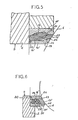
- Figure 5 est une vue partielle, en coupe, d'une autre forme d'exécution du dispositif,
- Figure 6 est une variante de réalisation du dispositif de figure 5.
- FIG. 1 is a view in longitudinal section of the valve assembly,
- FIGS. 2 and 3 are partial views showing, on an enlarged scale, the sealing device respectively at rest and when it is subjected to hydrostatic pressure,
- FIG. 4 is a sectional view showing an alternative embodiment of the cross section of the deformable ring,
- FIG. 5 is a partial view, in section, of another embodiment of the device,
- Figure 6 is an alternative embodiment of the device of Figure 5.
De façon connue, ce robinet est composé d'un corpe (2) associé a un chapeau (3) et d'un tournant (4). Ce tournant est solidaire de deux boute d'arbre, respectivement, (5) monté libre en rotation dans le corps, et (6) monté libre en rotation dans le chapeau. Le bout d'arbre (6) traverse le chapeau et comporte, à son extrémité, un carre d'entraînement (7) appelé à coopérer avec un organe de manoeuvre. Sur le corpe (2), sont rapportées des brides de raccordement (8) comportant chacune un canal interne (9) pour le passage au fluide. Le tournant (4) comporte également au moine un canal intérieur (10) apte à venir dans le prolongenent des canaux (9) des deux brides précitéée. L' étanchéité entre le corpe et le tournant est assurée par un dispositif désigné de façon générale par (12).In known manner, this tap is composed of a body (2) associated with a cap (3) and a turn (4). This turn is integral with two shaft bottles, respectively, (5) mounted free in rotation in the body, and (6) mounted free in rotation in the cap. The end of the shaft (6) passes through the cap and comprises, at its end, a drive edge (7) called to cooperate with an operating member. On the body (2), connection flanges (8) are added, each comprising an internal channel (9) for the passage to the fluid. The turn (4) also includes an internal channel (10) for the monk capable of coming into the extension of the channels (9) of the two aforementioned flanges. The seal between the body and the turn is ensured by a device generally designated by (12).
Selon l'invention, et comme montré plus en détail à la figure 2, ce dispositif d' étanchéité est composé d'un joint annulaire (13) disposé avec une bague (14) en matériau déformable élatiquement dans un logement annulaire ménagé autour du canal correspondant pour le passage du fluide. Le joint annulaire d'étanchéité (13) est réalisé en matière synthétique de type plastomére, tandis que la bague déformable (14) est réalisée dans une matière synthétique de type élastomère.According to the invention, and as shown in more detail in Figure 2, this sealing device is composed of an annular seal (13) arranged with a ring (14) of elastically deformable material in an annular housing formed around the channel corresponding for the passage of the fluid. The annular seal (13) is made of plastic material of the plastomer type, while the deformable ring (14) is made of a plastic material of the elastomer type.
Dans la forme d'exécution représentée, le logement annulaire contenant le joint (13) et la bague (14) est lui-même délimité par une bague intérieure (16) et par une bague extérieure (17). La bague intérieure (16) est réalisée en métal et, dans cette forme d'exécution, est emmanchée dans la bride (8) de raccordement. La bague extérieure (17), qui est réalieée en matière synthétique de type plastomère, est logée dans un alésage (18) du corps, c'est-à-dire peut coulisser par rapport à ce corps.In the embodiment shown, the annular housing containing the seal (13) and the ring (14) is itself delimited by a ring inner (16) and by an outer ring (17). The inner ring (16) is made of metal and, in this embodiment, is fitted into the connection flange (8). The outer ring (17), which is made of plastomer-type synthetic material, is housed in a bore (18) of the body, that is to say can slide relative to this body.
La bague intérieure (16) assure le guidage du joint annulaire (13) et s'oppose à son éventuelle extrusion par la pression. A cette fin, le jeu existant entre son extrémité libre (16a) et le tournant (4) est très réduit. Cette bague (16) comporte également un ou plusieurs canaux (19) mettant en communication le canal (9) de passage du fluide avec le logement annulaire (15). Ce canal est disposé de manière à communiquer avec la partie du logenent annulaire (15) contenant la bague déformable (14) qui, par ailleuse, a une section transversale supérieure à la section transversale du joint annulaire (13). La bague extérieure (17) assure les mêmes fonctions que celle intérieure (16). Elle comporte également, à son extrémité libre, un chanfrein (17a) délimitant une portée conique apte à venir en contact gliesant avec le tournant (4).The inner ring (16) guides the annular seal (13) and opposes its possible extrusion by pressure. To this end, the play existing between its free end (16a) and the turn (4) is very reduced. This ring (16) also includes one or more channels (19) putting the fluid passage channel (9) into communication with the annular housing (15). This channel is arranged so as to communicate with the part of the annular housing (15) containing the deformable ring (14) which, by the way, has a cross section greater than the cross section of the annular seal (13). The outer ring (17) performs the same functions as the inner one (16). It also comprises, at its free end, a chamfer (17a) delimiting a conical bearing capable of coming into sliding contact with the turn (4).
Dans ce dispositif, l'étanchéité est assurée par la différence des pressions régnant entre l'orifice d'arrivée du fluide et le volume fonctionnel intérieur du robinet qui ne sort pas au passage du fluide, c'est-à-dire par différence de pression de part et d'autre de l'ensemble d' étanchéité continu et déformable compose du joint annulaire (13) et de la bague deformable (14). Ainsi, lorsque l'un des canaux (9) de passage du fluide est soumis à la pression hydrostatique du fluide, celle-ci est dirigée par les canaux (19) directement contre la bague déformable (14). Sous l'effet de cette pression, la bague se déforme, comme montré figure 3. Cette déformation augmente son appui contre le fond du logement annulaire (15), mais aussi et, surtout, contre le joint annulaire (13) qui est ainsi plaqué contre le tournant (14) avec un effort qui est proportionnel à la pression hydrostatique du fluide arrivant au robinet.In this device, the seal is ensured by the difference in pressures prevailing between the fluid inlet orifice and the interior functional volume of the valve which does not come out when the fluid passes, that is to say by difference of pressure on either side of the continuous and deformable sealing assembly composed of the annular seal (13) and the deformable ring (14). Thus, when one of the channels (9) for the passage of the fluid is subjected to the hydrostatic pressure of the fluid, this is directed by the channels (19) directly against the deformable ring (14). Under the effect of this pressure, the ring deforms, as shown in Figure 3. This deformation increases its support against the bottom of the annular housing (15), but also and, above all, against the annular seal (13) which is thus pressed against the turn (14) with a force which is proportional to the hydrostatic pressure of the fluid arriving at the tap.
Lorsqu'au contraire, l'orifice de raccordement est à l'échappement, la pression régnant dans le volume fonctionnel du robinet parvient, par le jeu existant entre la bague extérieure (17) et l'alésage (18) du corps,au logement annulaire (15) et s'exerce ainsi sur la bague déformable (14). Cette dernière vient en compression radiale contre la bague intérieure (18) et, de la même façon que précédemment, exerce sur le joint annulaire (13) un effort tendant à plaquer ce dernier contre le tournant sphérique pour assurer l'étanchéité. Il est à noter que, si besoin est, et notamment pour les robinets travaillant à basse pression, le jeu existant entre la bague extérieure (17) et le corps (18) peut être augmenté. Pour les mêmes raisons, des canaux ou rainures peuvent être ménagés dans la bague (17) pour faciliter l'accès de la pression au logement annulaire (15). Avantageusement, pour éviter que la bague extérieure (17) tende à se déplacer en direction du tournant (4), lorsque la bague déformable (14) est déformée par la pression et, en d'autres termes, pour éviter que la bague extérieure (17), en venant en appui contre le tournant, augmente le couple résistant s'opposant à la rotation de ce tournant, cette bague (17) comporte,dans sa partie postérieure et à proximité du fond du logenent annulaire, une face pentue (17b) d'appui pour la bague déformable (14). De la sorte, lorsque la bague se déforme, et en même temps qu'elle tend à pousser le joint annulaire (13) contre le tournant, elle communique à la bague (17) un effort de sens inverse tendant à éloigner cette bague du tournant (4).When, on the contrary, the connection orifice is at the exhaust, the pressure prevailing in the functional volume of the valve reaches, through the play existing between the outer ring (17) and the bore (18) of the body, annular (15) and is thus exerted on the deformable ring (14). The latter comes in radial compression against the inner ring (18) and, in the same way as previously, exerts on the annular seal (13) a force tending to press the latter against the ball to ensure sealing. It should be noted that, if necessary, and in particular for taps working at low pressure, the clearance existing between the outer ring (17) and the body (18) can be increased. For the same reasons, channels or grooves can be made in the ring (17) to facilitate access of the pressure to the annular housing (15). Advantageously, to prevent the outer ring (17) from tending to move in the direction of the turn (4), when the deformable ring (14) is deformed by pressure and, in other words, to prevent the outer ring ( 17), by coming into abutment against the turn, increases the resistive torque opposing the rotation of this turn, this ring (17) comprises, in its rear part and near the bottom of the annular housing, a sloping face (17b ) support for the deformable ring (14). In this way, when the ring is deformed, and at the same time as it tends to push the annular seal (13) against the turn, it communicates to the ring (17) a force of opposite direction tending to move this ring away from the turn (4).
Dans la forme d'exécution représentée aux figures 2 et 3, la bague déformable (14) comporte un bourrelet périphérique (14a) se logeant dans une gorge (20) de la bague (17). Cette gorge comporte deux faces latérales inclinées en direction du fond du logement annulaire (15), à savoir la face pentue (17b) précitée, et une face (17c) qui, dans cette forme d'exécution, est moins inclinée que la précédente. La largeur de cette gorge est déterminée de manière que le bourrelet (14a) ne puisse, en aucun cas, venir en contact avec la face (17c), afin que, sous l'effet de la déformation de cette bague (14), la bague extérieure (17) soit exclusivement soumise à un effort tendant à l'éloigner du tournant (4).In the embodiment shown in Figures 2 and 3, the deformable ring (14) has a peripheral bead (14a) which is received in a groove (20) of the ring (17). This groove has two lateral faces inclined in the direction of the bottom of the annular housing (15), namely the sloping face (17b) mentioned above, and a face (17c) which, in this embodiment, is less inclined than the previous one. The width of this groove is determined so that the bead (14a) can in no case come into contact with the face (17c), so that, under the effect of the deformation of this ring (14), the outer ring (17) is exclusively subjected to a force tending to move it away from the turn (4).
Dans la variante de réalisation représentée à la figure 4, la bague déformable (14) comporte des faces antérieures (14b) et postérieure (14c) qui sont concaves afin de faciliter sa déformation sous l'effet de la pression hydrostatique.In the variant embodiment shown in FIG. 4, the deformable ring (14) has anterior (14b) and posterior (14c) faces which are concave in order to facilitate its deformation under the effect of hydrostatic pressure.
Il est à noter que l'étanchéité sur les bouts d'arbre (5) et (6) du tournant est obtenue par déformation d'un joint à lèvre (23) prenant appui contre une bague de centrage (22), ce qui réduit les frottements du tournant et facilite donc sa manoeuvre.It should be noted that the seal on the shaft ends (5) and (6) of the turn is obtained by deformation of a lip seal (23) bearing against a centering ring (22), which reduces the friction of the turn and therefore facilitates its operation.
Ce dispositif d'étanchéité satisfait aussi aux règles de sécurité au feu, puisqu'en cas d'incendie et de destruction du joint (13), de la bague déformable (14) et de la bague extérieure (17), la bague intérieure métallique (18), de même que la bague extérieure (17), venant très près du tournant (4) et sans contact avec lui, assure une étanchéité résiduelle dans les conditions pratiques de l'étanchéité "fire-safe" des applications du pétrole.This sealing device also meets the fire safety rules, since in the event of fire and destruction of the seal (13), the deformable ring (14) and the outer ring (17), the inner metal ring (18), as well as the outer ring (17), coming very close to the turn (4) and without contact with it, ensures a residual seal under the practical conditions of "fire-safe" sealing of petroleum applications.
Il est évident que l'invention ne se limite pas à la seule forme d'exécution qui a été décrite ci- dessus; elle en embrasse les variantes de réalisation comportant des moyens équivalents, quelles que soient notamment la forme de la section de la bague (14) et la structure interne des différents composants; c'est ainsi que la bague extérieure (17) réalisée en plastomère peut être renforcée par une armature métallique, ou même exécutée entièrement en matériau métallique.It is obvious that the invention is not limited to the only embodiment which has been described above; it embraces the variant embodiments comprising equivalent means, whatever the shape of the section of the ring (14) and the internal structure of the various components in particular; this is how the outer ring (17) made of plastomer can be reinforced by a metal frame, or even made entirely of metallic material.
La forme d'exécution de la figure 5 se différencie des précédentes par le fait que la bague intérieure (18,) est montée libre en translation dans le corps (2) au même titre que la bague extérieure (17'). De plus, cette bague intérieure (18') est liée en translation au joint annulaire (13'). Cette liaison. est assurée par une collerette (23) de la bague (16') apte à coopérer avec une collerette (24) du joint (13'). En outre,la bague déformable (14') présente, au repos, la forme d'un anneau à section transversale rectangulaire. Cette bague est mise en place dans le logement (15) formé entre les bagues (18') et (17') et délimité transversalement par une paroi diamétrale du corps (2) et par une face inclinée (25) dujoint (13'). Grâce à cette disposition, la bague déformable (14') prend appui, par deux de ses angles arrondis opposés, respectivement sur la face diamétrale du corps (2) et sur la face (25) du joint annulaire (13,).The embodiment of Figure 5 differs from the previous ones in that the inner ring (18,) is mounted free in translation in the body (2) in the same way as the outer ring (17 '). In addition, this inner ring (18 ') is linked in translation to the annular seal (13'). This connection. is provided by a flange (23) of the ring (16 ') capable of cooperating with a flange (24) of the seal (13'). In addition, the deformable ring (14 ') has, at rest, the shape of a ring with rectangular cross section. This ring is placed in the housing (15) formed between the rings (18 ') and (17') and delimited transversely by a diametrical wall of the body (2) and by an inclined face (25) of the joint (13 ') . Thanks to this arrangement, the deformable ring (14 ') is supported, by two of its opposite rounded angles, respectively on the diametrical face of the body (2) and on the face (25) of the annular seal (13,).
La bague (14') est réalisée dans une matière synthétique de type élastomère, tandis que le joint annulaire (13') est réalisé dans une matière synthétique de type plastomère et que les deux bagues de guidage (16') et (17') sont réalisées dans des matériaux rigides et indéformables, de type métallique ou synthétique.The ring (14 ') is made of a synthetic material of the elastomer type, while the annular seal (13') is made of a synthetic material of the plastomer type and that the two guide rings (16 ') and (17') are made of rigid and non-deformable materials, of metallic or synthetic type.
Comme dans la forme d'exécution précédente, la bague intérieure (16') comporte un canal (19) faisant communiquer le logement (15) avec le canal de passage du fluide. Dans le même but, la bague extérieure (17') est munie d'un canal (26) permettant la communication du logement (15) avec la partie intérieure du robinet.As in the previous embodiment, the inner ring (16 ') has a channel (19) communicating the housing (15) with the fluid passage channel. For the same purpose, the outer ring (17 ') is provided with a channel (26) allowing communication of the housing (15) with the inner part of the valve.
La bague intérieure (16') comporte une gorge pour un joint de section carrée (27) maintenu en place par la bague déformable (14') et constituant bague anti-extrusion.The inner ring (16 ') has a groove for a square section seal (27) held in place by the deformable ring (14') and constituting an anti-extrusion ring.
Grâce à cette construction, le dispositif d'étanchéité forme un ensemble pratiquement monobloc pouvant être facilement manipulé et mis en place dans le corps du robinet.Thanks to this construction, the sealing device forms a practically one-piece assembly which can be easily manipulated and placed in the body of the valve.
Dans la variante de réalisation de figure 6, la bague déformable est constituée par au moins deux joints toriques (28) qui, même en l'absence de pression, sont en contact d'étanchéité l'un avec l'autre et avec les faces du logement annulaire (15).In the variant embodiment of FIG. 6, the deformable ring consists of at least two O-rings (28) which, even in the absence of pressure, are in sealing contact with each other and with the faces annular housing (15).
Exceptées ces différences, le dispositif est similaire à celui de figure 5 et procure d'excellents résultats.Except for these differences, the device is similar to that of FIG. 5 and provides excellent results.
Il est à noter que dans tous ces dispositifs, les déformations des moyens d'étanchéité s'effectuent uniquement en milieu déformable, de type élastomère ou plastomère, et ne sont pas sensibles aux phénomènes de plaquage hydraulique affectant des surfaces métalliques, comme c'est le cas dans les dispositifs habituels.It should be noted that in all these devices, the deformations of the sealing means are carried out only in a deformable medium, of the elastomer or plastomer type, and are not sensitive to the phenomena of hydraulic plating affecting metal surfaces, as is the case in the usual devices.
Claims (6)
characterised in that the annular housing (15) is defined by two coaxial rings (15-17), respectively an inner ring (15-15') and an outer ring (17-17'), by the annular gasket (13) which is arranged between the two coaxial rings and by a connecting flange (8);
Applications Claiming Priority (2)
| Application Number | Priority Date | Filing Date | Title |
|---|---|---|---|
| FR8210085A FR2528144A1 (en) | 1982-06-07 | 1982-06-07 | SEALING DEVICE FOR A SPHERICAL ROTARY TAP |
| FR8210085 | 1982-06-07 |
Publications (2)
| Publication Number | Publication Date |
|---|---|
| EP0096645A1 EP0096645A1 (en) | 1983-12-21 |
| EP0096645B1 true EP0096645B1 (en) | 1986-10-15 |
Family
ID=9274834
Family Applications (1)
| Application Number | Title | Priority Date | Filing Date |
|---|---|---|---|
| EP83420095A Expired EP0096645B1 (en) | 1982-06-07 | 1983-06-07 | Sealing device for a spherical plug valve |
Country Status (4)
| Country | Link |
|---|---|
| US (1) | US4511150A (en) |
| EP (1) | EP0096645B1 (en) |
| DE (1) | DE3367011D1 (en) |
| FR (1) | FR2528144A1 (en) |
Families Citing this family (34)
| Publication number | Priority date | Publication date | Assignee | Title |
|---|---|---|---|---|
| JPS59194175A (en) * | 1983-04-12 | 1984-11-02 | Kobe Steel Ltd | Sealing mechanism for ball valve |
| DK158016C (en) * | 1984-07-11 | 1990-08-13 | Broen Armatur As | PROCEDURE FOR INSTALLING A BALL VALVE |
| US4796858A (en) * | 1987-10-01 | 1989-01-10 | Halliburton Company | Dual seal valve |
| US5299701A (en) * | 1989-02-03 | 1994-04-05 | Senetics, Inc. | Indicator cap |
| US5205536A (en) * | 1992-09-24 | 1993-04-27 | Newport News Shipbuilding And Dry Dock Company | Top entry, trunnion-type ball valve |
| CA2315777C (en) | 1998-01-16 | 2008-12-23 | 1263152 Ontario Inc. | Indicating device for use with a dispensing device |
| US6142339A (en) * | 1998-01-16 | 2000-11-07 | 1263152 Ontario Inc. | Aerosol dispensing device |
| US6336453B1 (en) | 1999-04-30 | 2002-01-08 | Trudell Medical International | Indicating device for aerosol container |
| US6082358A (en) | 1998-05-05 | 2000-07-04 | 1263152 Ontario Inc. | Indicating device for aerosol container |
| US6729330B2 (en) | 1998-05-05 | 2004-05-04 | Trudell Medical International | Indicating device for aerosol container |
| US6745760B2 (en) | 2001-05-15 | 2004-06-08 | Trudell Medical International | Medicament applicator |
| ITBS20010071U1 (en) * | 2001-07-27 | 2003-01-27 | Enolgas Bonomi S P A | TOROIDAL COMPOSITE GASKET FOR BALL VALVES |
| US7004164B2 (en) * | 2002-03-21 | 2006-02-28 | Trudell Medical International | Indicating device for aerosol container |
| US7621273B2 (en) * | 2003-10-28 | 2009-11-24 | Trudell Medical International | Indicating device with warning dosage indicator |
| US7100530B2 (en) | 2003-12-15 | 2006-09-05 | Trudell Medical International, Inc. | Dose indicating device |
| US7543582B2 (en) | 2004-09-20 | 2009-06-09 | Trudell Medical International | Dose indicating device with display elements attached to container |
| JP5189369B2 (en) * | 2005-01-20 | 2013-04-24 | トルーデル メディカル インターナショナル | Dispensing device |
| US7544293B2 (en) | 2005-09-26 | 2009-06-09 | Semba Inc. | Valve and process for interrupted continuous flow chromatography |
| US8141550B2 (en) | 2006-08-01 | 2012-03-27 | Trudell Medical International | Dispensing device |
| US7790040B2 (en) | 2006-08-30 | 2010-09-07 | Semba Biosciences, Inc. | Continuous isocratic affinity chromatography |
| US8807164B2 (en) * | 2006-08-30 | 2014-08-19 | Semba Biosciences, Inc. | Valve module and methods for simulated moving bed chromatography |
| US8082873B2 (en) * | 2008-05-05 | 2011-12-27 | Trudell Medical International | Drive mechanism for an indicating device |
| US8181591B1 (en) | 2008-05-23 | 2012-05-22 | Trudell Medical International | Domed actuator for indicating device |
| US8196603B2 (en) | 2008-08-20 | 2012-06-12 | Semba Biosciences, Inc. | Valve block assembly |
| EP2626098B1 (en) | 2008-10-22 | 2020-08-19 | Trudell Medical International | Modular aerosol delivery system |
| DE102009006904A1 (en) * | 2009-01-30 | 2010-08-12 | Audi Ag | Sealing arrangement for a rotary valve |
| US20120153206A1 (en) * | 2010-12-16 | 2012-06-21 | Zipson Steel Industrial Co., Ltd. | Ball Valve |
| WO2012158724A1 (en) * | 2011-05-16 | 2012-11-22 | Seaboard International Inc. | Valve seat and valve |
| US8955541B2 (en) * | 2012-12-21 | 2015-02-17 | Fisher Regulators (Shanghai) Co., Ltd. | Disc assembly with branch hole for fluid flow control device |
| GB201319224D0 (en) * | 2013-10-31 | 2013-12-18 | Clyde Process Ltd | Powder isolating valve |
| KR20180130493A (en) * | 2016-02-18 | 2018-12-07 | 가스켓 인터내셔널 에스.알.엘. | A ball valve comprising a sealing assembly for a ball valve and a sealing assembly |
| CN111201392A (en) * | 2017-08-10 | 2020-05-26 | 嘉士凯国际有限责任公司 | Seal assembly for a ball valve and ball valve comprising such a seal assembly |
| CN107631051A (en) * | 2017-10-17 | 2018-01-26 | 兰州高压阀门有限公司 | A kind of double sealing structure for cryogenic ball valve valve seat |
| EP3940275A1 (en) * | 2020-07-17 | 2022-01-19 | Goodrich Corporation | Valve assembly |
Family Cites Families (13)
| Publication number | Priority date | Publication date | Assignee | Title |
|---|---|---|---|---|
| DE520188C (en) * | 1926-03-16 | 1931-03-09 | Charmilles Sa Ateliers | Sealing device for pressure water pipe valve |
| US2653004A (en) * | 1942-10-07 | 1953-09-22 | Von Roll Ag | Pivoted stop valve |
| AT167771B (en) * | 1942-10-07 | 1951-02-26 | Von Roll Ag | Rotary valve used to close pipelines |
| GB716610A (en) * | 1951-03-20 | 1954-10-13 | Kac Ltd | Improvements in or relating to pipe and hose couplings |
| US2845247A (en) * | 1951-11-13 | 1958-07-29 | Fyr Fyter Co | Control valve for fire hose lines |
| US2916254A (en) * | 1954-12-13 | 1959-12-08 | Hale Fire Pump Co | Rotary valves |
| US3556476A (en) * | 1968-07-11 | 1971-01-19 | Fwi Inc | Butterfly valve having improved positive closure means |
| AT304977B (en) * | 1969-06-27 | 1973-02-12 | Schaeffer & Budenberg Gmbh | Sealing of a butterfly valve or control valve by means of an O-ring |
| US3722859A (en) * | 1971-03-22 | 1973-03-27 | Walworth Co | Ball valve seal for high temperature operation |
| DE2131643C3 (en) * | 1971-06-25 | 1975-01-02 | Wsesojusny Nautschno-Issledowatelskij I Proektnokonstruktorskij Institut Po Rasrabotke Gasopromyslowowo Oborudowanija, Saratow (Sowjetunion) | Sealing and plug wiping device for a tap |
| FR2196699A5 (en) * | 1972-07-18 | 1974-03-15 | Auxim | |
| GB2023773A (en) * | 1978-06-21 | 1980-01-03 | Weir Pacific Valves Ltd | Seats for rotary ball valves |
| US4286614A (en) * | 1979-09-19 | 1981-09-01 | Acf Industries, Incorporated | High temperature ball valve |
-
1982
- 1982-06-07 FR FR8210085A patent/FR2528144A1/en active Granted
-
1983
- 1983-06-07 EP EP83420095A patent/EP0096645B1/en not_active Expired
- 1983-06-07 US US06/501,981 patent/US4511150A/en not_active Expired - Fee Related
- 1983-06-07 DE DE8383420095T patent/DE3367011D1/en not_active Expired
Also Published As
| Publication number | Publication date |
|---|---|
| DE3367011D1 (en) | 1986-11-20 |
| EP0096645A1 (en) | 1983-12-21 |
| FR2528144A1 (en) | 1983-12-09 |
| FR2528144B1 (en) | 1985-02-01 |
| US4511150A (en) | 1985-04-16 |
Similar Documents
| Publication | Publication Date | Title |
|---|---|---|
| EP0096645B1 (en) | Sealing device for a spherical plug valve | |
| EP0166641B1 (en) | Sealing device assuring the opstream/downstream fluid tightness of a closure member | |
| EP0231673B1 (en) | Composite sealing arrangement | |
| FR2538875A1 (en) | ROTATING CONNECTOR AND SEAL FOR FLUIDS | |
| EP1433988B1 (en) | Regulation valve | |
| FR2497905A2 (en) | DOUBLE FLEXIBLE O-RING | |
| EP0165186A1 (en) | Spherical plug valve | |
| CA3018005A1 (en) | Dynamic seal device | |
| EP0821190B1 (en) | Metal seal, in particular for fitting device | |
| EP0292346B1 (en) | Sealing element incorporating a reaction ring, especially for a stop valve | |
| EP0202156A1 (en) | Anular sealing device, especially for valves or taps | |
| FR2555279A1 (en) | ANNULAR SEALING SEAL IN ELASTOMER | |
| FR2594520A1 (en) | ROD END SEAL FOR STOP VALVE | |
| FR2683289A1 (en) | Seal for a butterfly valve and butterfly valve provided with such a seal | |
| FR2520469A1 (en) | MECHANICAL FRONTAL JOINT | |
| FR2658872A1 (en) | Improvements made to thrust cylinders for pressurised fluid | |
| EP0350394B1 (en) | Rainwater drainage system | |
| FR2507733A1 (en) | VALVE WITH DIRECT PASSAGE | |
| FR2645235A1 (en) | SEALING ASSEMBLY AND ROTARY ACTUATOR CONTROLLED BY A FLUID AND COMPRISING THE SAME | |
| FR2559869A1 (en) | THE STOP VALVE | |
| FR2609140A1 (en) | Ball-valve | |
| FR2610382A1 (en) | Sealing gasket and assembly | |
| FR2549566A1 (en) | Stopcock for high operational pressures | |
| EP4305328A1 (en) | Expansion valve comprising a movable slide | |
| EP0819076A1 (en) | Tandem master cylinder with an improved sealing function |
Legal Events
| Date | Code | Title | Description |
|---|---|---|---|
| PUAI | Public reference made under article 153(3) epc to a published international application that has entered the european phase |
Free format text: ORIGINAL CODE: 0009012 |
|
| AK | Designated contracting states |
Designated state(s): BE CH DE GB IT LI |
|
| 17P | Request for examination filed |
Effective date: 19840618 |
|
| GRAA | (expected) grant |
Free format text: ORIGINAL CODE: 0009210 |
|
| AK | Designated contracting states |
Kind code of ref document: B1 Designated state(s): BE CH DE GB IT LI |
|
| ITF | It: translation for a ep patent filed |
Owner name: JACOBACCI & PERANI S.P.A. |
|
| REF | Corresponds to: |
Ref document number: 3367011 Country of ref document: DE Date of ref document: 19861120 |
|
| PLBE | No opposition filed within time limit |
Free format text: ORIGINAL CODE: 0009261 |
|
| STAA | Information on the status of an ep patent application or granted ep patent |
Free format text: STATUS: NO OPPOSITION FILED WITHIN TIME LIMIT |
|
| 26N | No opposition filed | ||
| PGFP | Annual fee paid to national office [announced via postgrant information from national office to epo] |
Ref country code: GB Payment date: 19900607 Year of fee payment: 8 |
|
| PGFP | Annual fee paid to national office [announced via postgrant information from national office to epo] |
Ref country code: BE Payment date: 19900620 Year of fee payment: 8 |
|
| PGFP | Annual fee paid to national office [announced via postgrant information from national office to epo] |
Ref country code: CH Payment date: 19900627 Year of fee payment: 8 |
|
| PGFP | Annual fee paid to national office [announced via postgrant information from national office to epo] |
Ref country code: DE Payment date: 19900628 Year of fee payment: 8 |
|
| ITTA | It: last paid annual fee | ||
| PG25 | Lapsed in a contracting state [announced via postgrant information from national office to epo] |
Ref country code: GB Effective date: 19910607 |
|
| PG25 | Lapsed in a contracting state [announced via postgrant information from national office to epo] |
Ref country code: LI Effective date: 19910630 Ref country code: CH Effective date: 19910630 Ref country code: BE Effective date: 19910630 |
|
| BERE | Be: lapsed |
Owner name: SOC. NOUVELLE AUXIM Effective date: 19910630 |
|
| GBPC | Gb: european patent ceased through non-payment of renewal fee | ||
| REG | Reference to a national code |
Ref country code: CH Ref legal event code: PL |
|
| PG25 | Lapsed in a contracting state [announced via postgrant information from national office to epo] |
Ref country code: DE Effective date: 19920401 |