EP0096626A1 - Device for forming parcels of electrodes for electrochemical generators - Google Patents
Device for forming parcels of electrodes for electrochemical generators Download PDFInfo
- Publication number
- EP0096626A1 EP0096626A1 EP83401078A EP83401078A EP0096626A1 EP 0096626 A1 EP0096626 A1 EP 0096626A1 EP 83401078 A EP83401078 A EP 83401078A EP 83401078 A EP83401078 A EP 83401078A EP 0096626 A1 EP0096626 A1 EP 0096626A1
- Authority
- EP
- European Patent Office
- Prior art keywords
- electrodes
- flap
- ribbon
- electrode
- loading station
- Prior art date
- Legal status (The legal status is an assumption and is not a legal conclusion. Google has not performed a legal analysis and makes no representation as to the accuracy of the status listed.)
- Withdrawn
Links
Images


Classifications
-
- H—ELECTRICITY
- H01—ELECTRIC ELEMENTS
- H01M—PROCESSES OR MEANS, e.g. BATTERIES, FOR THE DIRECT CONVERSION OF CHEMICAL ENERGY INTO ELECTRICAL ENERGY
- H01M10/00—Secondary cells; Manufacture thereof
- H01M10/06—Lead-acid accumulators
- H01M10/12—Construction or manufacture
- H01M10/14—Assembling a group of electrodes or separators
-
- Y—GENERAL TAGGING OF NEW TECHNOLOGICAL DEVELOPMENTS; GENERAL TAGGING OF CROSS-SECTIONAL TECHNOLOGIES SPANNING OVER SEVERAL SECTIONS OF THE IPC; TECHNICAL SUBJECTS COVERED BY FORMER USPC CROSS-REFERENCE ART COLLECTIONS [XRACs] AND DIGESTS
- Y02—TECHNOLOGIES OR APPLICATIONS FOR MITIGATION OR ADAPTATION AGAINST CLIMATE CHANGE
- Y02E—REDUCTION OF GREENHOUSE GAS [GHG] EMISSIONS, RELATED TO ENERGY GENERATION, TRANSMISSION OR DISTRIBUTION
- Y02E60/00—Enabling technologies; Technologies with a potential or indirect contribution to GHG emissions mitigation
- Y02E60/10—Energy storage using batteries
-
- Y—GENERAL TAGGING OF NEW TECHNOLOGICAL DEVELOPMENTS; GENERAL TAGGING OF CROSS-SECTIONAL TECHNOLOGIES SPANNING OVER SEVERAL SECTIONS OF THE IPC; TECHNICAL SUBJECTS COVERED BY FORMER USPC CROSS-REFERENCE ART COLLECTIONS [XRACs] AND DIGESTS
- Y02—TECHNOLOGIES OR APPLICATIONS FOR MITIGATION OR ADAPTATION AGAINST CLIMATE CHANGE
- Y02P—CLIMATE CHANGE MITIGATION TECHNOLOGIES IN THE PRODUCTION OR PROCESSING OF GOODS
- Y02P70/00—Climate change mitigation technologies in the production process for final industrial or consumer products
- Y02P70/50—Manufacturing or production processes characterised by the final manufactured product
Definitions
- the present invention relates to a device for forming electrode packages for electrochemical cells by winding a ribbon of a nonwoven material around the lateral edges of the electrodes starting from an electrode located in the center of this package and going to its external electrodes.
- connection lugs of the electrodes are positioned vertically in a rotary template, this template rotating by half a turn each time an electrode of another polarity must be added to constitute the package. It turned out that the stresses thus exerted on the connection lugs, in particular. when they are made of lead, corrme this is the case for a large number of electrochemical generators, exceed the resistance of these connection lugs and deform them.
- the object of the present invention is to remedy the drawbacks of this device, while retaining the advantages linked to the mode of formation of the electrode packet.
- the subject of the present invention is a device for forming packets of electrodes for electrochemical generators, by winding a ribbon of a nonwoven material around the lateral edges of the electrodes starting from an electrode located at the center of this package and going to its external electrodes.
- This device is characterized by the fact that it comprises a roller for feeding said ribbon, a station for loading electrodes in a substantially horizontal position arranged along the path of unwinding of this ribbon, means for supplying this station with electrodes, a tilting member mounted around an axis transverse to said unwinding path, and located in the initial position at the loading station under the passage of the tape, a flap also articulated around an axis transverse to this path and adjacent to that of said path tilting member, this flap extending in its initial position from the loading station towards the ribbon supply roller under the passage of this ribbon, drive means for tilting said flap towards said loading station, this flap driving a portion of ribbon equivalent to its length towards this member, drive means for tilting this rocking member and to return the flap to its initial position and a pusher to then slide the package in formation of said flap in the initial position towards the loading station.
- the advantage of this device lies in the fact that the electrodes are no longer subjected to stresses liable to damage them, in particular for unwinding the nonwoven from the supply roll. During their tilting, the electrodes are held by pinching. The tension on the ribbon can be adjusted so as to form a packet of electrodes in which the nonwoven ribbon clamps the electrodes with the desired tension.
- the formation of the packet of electrodes in a horizontal position makes it possible to integrate the device into a production line, the finished packets being able to be removed by conveyor belt without any manipulation as will be explained below.
- the reliability of the device and its full automation allow an appreciable gain in productivity.
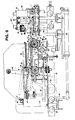
- Fig. 1 illustrates the entire device so as to be able to locate the various mechanisms which make it up tie and which will be described later.
- This device comprises a frame 1 on which is mounted a supply carriage 2 of the electrodes 3, movable transversely to a packaging mechanism situated on the path described by a ribbon of a nonwoven material 4 between a supply roller 5 and an outlet 6 of the packets of packed electrodes.
- each drive slide 16 and 17 is associated with a jack 8 respectively 9, the rod of one 8 is fixed to an intermediate slide 10 mounted on the bars 7, while the rod of the other 9 is fixed to an intermediate slide 11 also mounted on the bars 7.
- Two coaxial jacks 12 and 13 are fixed in mirror symmetry between a central support 14 secured to the frame 1 and two supports 15, also secured to the frame and only one of which is illustrated. The rod of the jack 12 is fixed to the intermediate slide 11 while that of the jack 13 is fixed to the intermediate slide 10.
- the feed carriage 2 has a clutch mechanism comprising a clutch finger 18 projecting laterally from a jack 19 (FIG. 3) integral with the feed carriage 2 intended to come into engagement with two coupling members. 20, 21 (fig. 2) provided with clearances 20a, 2la for receiving the clutch finger 18 and secured respectively to the driving slides 16 and 17.
- a clutch mechanism comprising a clutch finger 18 projecting laterally from a jack 19 (FIG. 3) integral with the feed carriage 2 intended to come into engagement with two coupling members. 20, 21 (fig. 2) provided with clearances 20a, 2la for receiving the clutch finger 18 and secured respectively to the driving slides 16 and 17.
- the intermediate slides 10 and 11 being fixed to the rods of the jacks 12 and 13 integral with the frame 1, when the clutch finger 18 is engaged with the coupling member 20, for example, when the rod of the jack 8 returns, the drive slide 16 which is integral with the jack 8 moves towards the intermediate slide 10 and drives with it the feed carriage 2 in a first position. If now the rod of the jack 13, integral with the intermediate slide 10, comes out of this jack, it causes the slides 10 and 16 and the carriage 2 to the right of FIG. 2 in a second position.
- the two positions to the left of the central position of the carriage 2 are symmetrical and controlled in the same way by the jacks 9 and 12 by moving the clutch finger 18 in the clearance 21a of the coupling member 21, after that the feed carriage 2 is returned to the central position illustrated in FIG. 2.
- This feed carriage 2 carries a gripper 22 for gripping the electrodes (FIGS. 3 and 4).
- This clamp 22 is slidably mounted on two guide rods 23 and is fixed to the end of the rod of a jack 24 mounted vertically on the carriage. It comprises two movable jaws 25 (fig. 4) each fixed to the end of an arm. elastic 26 and two abutment surfaces 22a. These two arms 26 can be separated from one another by the rod of a jack 27 so as to elastically separate the jaws 25 from one another.
- This mechanism includes an electrode charging station 3 located exactly below the clamp 22 of the feed carriage 2 when this carriage occupies the central position illustrated in FIG. 2.
- This loading station has a conveyor with endless belts 28, these being mounted on rollers 29 and 30 secured to two parallel axes 31 respectively 32.
- This loading station also includes an elevator 33 mounted to slide vertically by means of a rod 34.
- a jack 35 integral with the frame 1, extends horizontally and is connected to the rod 34 of the elevator 33 by the intermediate a belt strand 36 passing over a mad pulley 37 tangent to the axis of the rod 34.
- This jack 35 is capable of placing the elevator 33 in two limit positions, the second of which is illustrated in dashed lines in FIG. . 6.
- Two rocker arms 38 are secured, at one of their ends, to a support 39 fixed by a screw 40 to the shaft 41 of a pinion 42 connected by a chain 43 to a drive pinion 44. These arms rockers 38, in the initial position in which they are drawn in solid lines in FIG.
- the support 39 of these rocking arms 38 also carries a flap 45 articulated freely around an axis 46 parallel to the shaft 41 and integral with this shaft 41.
- This flap 45 is capable of occupying different positions, one of which is illustrated in solid lines and the others in dashed lines (fig. 6). Two of the positions illustrated in dashed lines are delimited by a cleat 47.
- This flap 45 is associated with a drive arm 48 secured to a pinion 49 (fig. 5) connected by a chain 50 (fig. 6) to a pinion 51.
- This drive arm 48 is movable between two limit positions illustrated in solid lines respectively in phantom.
- Two guide rails 52 are mounted laterally along the packaging mechanism. These rails 52 guide a push cart 53 mounted on rollers 54. This push cart 53 is connected to a rod of an actuating cylinder 55 by a connecting rod 56. This cart 53 carries a push 57 located at the level of the upper face of the flap 45 when the latter rests on the cleat 47 and is horizontal as illustrated in phantom.
- a second conveyor with endless belts 58 follows the first conveyor 28, its upper strand being at the same level as that of this conveyor 28.
- a welding carriage 59 is mounted along the rails 52 by means of rollers 60. This welding carriage 59 is fixed to the rod of an actuating cylinder 61 (fig. 5) and has two columns 62 on which a support block 63 is slidably mounted. Two horizontal arms 64 start from this block 63 and carry a welding head 65 essentially constituted by a heating resistor.
- the support block 63 is controlled by the rod of a jack 66 (fig. 6) arranged vertically and fixed to the base of the carriage 59.
- a heating wire 67 (figs 5 and 8) is stretched between two fixing tabs 68 welded to a rod 69, one end of which is fixed to a ring 70 screwed on a vertical slide 71.
- a second rod 72 is fixed to the ring 70 and rests on a plate 73 secured to the end of a jack 74 arranged vertically, which makes it possible to raise the heating wire 67 between the upper strands of the carriers 28 and 58 to cut by fusion the nonwoven tape 4 (illustrated only by fig: 1) made of thermoplastic material.
- a folding member 75 of the nonwoven tape 4 cut by the heating wire 67 is mounted coaxially with the axis 32 of the rollers 30 (FIG. 6).
- This folding member 75 comprises a series of studs 76, integral with an elastic arm 77, fixed to a stirrup 78 fixed to a drive pinion 79 freely mounted on the axis 32 (fig. 7).
- This folding member 75 is capable of being brought from the position illustrated in solid lines in FIG. 6 in the position illustrated in phantom in this same figure.
- Another folding member 80 of the other end of the nonwoven tape 4 is mounted integral with a pinion 81 (FIG. 5) connected by a chain 82 to a drive pinion 83, and is capable of occupying or the position illustrated in solid lines in FIG. 6, or that illustrated in dashed lines.
- This folding member 80 is also associated with a folding lever 84 (FIG. 6) articulated around an axis 85 and actuated by a jack 86.
- the two endless belt conveyors 28 and 58 are driven from a common drive pinion 87 and an endless chain 88.
- An electrode supply station 3 is arranged laterally on each side of the belt conveyor endless 28 constituting the electrode charging station.
- These feed stations only one of which is illustrated in FIG. 5, have a feed plate 89 rotatably mounted on a vertical drive shaft 90 and on which are positioned four stacks of electrodes 3 of the same polarity. Two of these stacks are aligned transversely to the conveyor 28 with their connection tabs appearing on the same longitudinal edge but adjacent respectively to the two opposite lateral edges of the electrodes 3.
- These electrodes 3 are also centered on the axis of movement of the clamp 22 mounted on the feed carriage 2 of figs 2, 3 and 4.
- the other two stacks of electrodes 3 placed on the feed plate 89 have an orientation similar to that of the two stacks of electrodes: - electrodes aligned on the transverse axis of the conveyor 28, but each rotated by 180 ° relative to the stack which is diametrically opposite to it on the feed plate 89, so that by turning this plate by 180 ° the two other stacks of electrodes 3 respectively occupy the place of the stack of electrodes which is diametrically opposite to it.
- the electrodes of the other feed plate not shown are all of the other polarity.
- the positions of the electrodes 3 on this other supply plate correspond to the positions of the electrodes 3 of the supply plate illustrated following a translation of this supply plate along an axis parallel to the axis of movement of the carriage d 2.
- the feed carriage 2 is brought by one of the jacks 8 and 9, according to the position of the clutch finger 18 ( Fig. 2), with respect to one of the stacks of positive or negative electrodes disposed on one of the supply plates 89. near the conveyor 28, the jacks 12 and 13 then remaining stationary.
- the clamp 22 is lowered with its movable jaws 25 separated by the jack 27 (figs 3 and 4). When the abutment surfaces 22a of this clamp 22 touch the top of the stack, it stops and the parts of the movable jaws 25 which extend below the plane of these abutment surfaces 22a (fig.
- the flap 45 is in the horizontal position pressing against the cleat 47, drawn in phantom.
- the rocker arms 38 are in the position drawn in solid line (FIG. 6), the elevator 33 is lowered and the drive arm 48 of the flap 45 is in the position drawn in phantom.
- the clamp 22 (fig. 3) is lowered to deposit the electrode 3, the first electrode of a new package, the pressure exerted by the electrode pulls the non-woven tape 4 by making it follow the vertical part of the support 39 to apply it against the belt conveyor 28.
- the clamp 22 rises, and the jack 74 causes the rod 69 and the heating wire 67 to be closed.
- the rod 69 spreads the studs 76 secured to the elastic arm 77 (fig. 6) and the hot wire cuts the nonwoven ribbon 4 between the conveyors 28 and 58.
- the heating wire 67 Once the heating wire 67 has returned to its initial position, it is the folding members 75 and 80 and the folding lever 84 which fold the cut ends of the nonwoven tape 4 respectively against the first electrode of the new package and against the finished package which is on the conveyor 58, in the positions of the folding member 75 and the folding lever 84 illustrated in lines mixed by fig. 6 and in the position of the folding member 80 illustrated in solid lines by this same figure.
- the welding head 65 welds the folded end of the nonwoven strip 4 of thermoplastic material against the pack of electrodes carried by the conveyor 58, in the position illustrated in solid lines in FIG. 6, after which the welding carriage 59 is moved by the jack 61 along the guide rails 52, above the other end of the cut nonwoven tape, folded against the first electrode placed on the conveyor 28.
- the cylinder 66 then lowers the welding head 65 to fix the end of this strip against the electrode.
- the drive arm 48 of the flap 45 passes from its position illustrated in dashed lines to its position illustrated in solid lines in FIG. 6.
- the flap 45 reaches the end position of the drive arm 48, it tans by the effect of its own weight against the first electrode placed on the conveyor 28.
- the flap drives with it the nonwoven tape by unrolling a corresponding length of the feed roller 5 which is illustrated only in FIG. 1.
- the electrode placed on the conveyor 28 is then completely enveloped by the nonwoven tape 4 which has not been shown feel in this fig. 6 for the sake of clarity.
- the support 39 of the rocking arms 38 then rotates in the opposite direction to that of the needles of a watch, as far as the position illustrated in dashed lines in FIG. 6.
- the flap 45 is pivoted about the axis 46 secured to the same support 39, it is then found in the position of support against the cleat 47 but inclined as shown in phantom.
- the support 39 then returns the rocking arms 38 to their initial position so that the flap 45 is brought, by its axis 46 integral with this support 39, to its horizontal position drawn in phantom in FIG. 6.
- the electrode, wrapped in the nonwoven ribbon remained on this flap 45.
- the elevator 33 is then moved by the jack 35 to the position illustrated in phantom in FIG. 6, that is to say exactly at the level of the upper face of the flap 45.
- the jack 55 pulls the pusher carriage 53 along the guide rails 52 so that the pusher 57 passes the wrapped electrode of the flap 45 on the elevator 33, by pulling a corresponding length of nonwoven ribbon and the pusher 57 and its carriage return alone to the position illustrated in solid lines in FIG. 6.
- the elevator 33 is returned to its initial position and deposits the packet of electrodes in formation on the belts of the conveyor 28.
- the carriage 2 carrying the clamp 22 (figs 2 to 4) is then brought opposite one of the stacks of electrodes carried by the other supply plate 89 on which the electrodes of the other polarity.
- the connection tab is now in an inverted position relative to its initial position. Since maintaining a second electrode is to be added, it is obviously chose the other polarity and its adjacent connecting pin at the side edge of the electrode opposite to the lateral edge of the first electrode adjacent to the connection tab of this first electrode, so that the connection tabs of the electrodes of the two polarities are adjacent to the two respective lateral edges of the pack of electrodes.
- the feed plate 89 has two stacks of electrodes, the connection tabs of which are adjacent to opposite lateral edges of the electrodes, it suffices then to bring the clamp 22 above the stack of electrodes whose connection tabs are in the desired orientation.
- the chosen electrode is placed on the first electrode with the interposition of the nonwoven ribbon enveloping this first electrode.
- this second electrode is itself rotated 180 ° around an axis parallel to its lateral edges and it is then below the first electrode.
- each feed plate 89 has two stacks of electrodes of the same polarity aligned in the path of the clamp 22, but with the connection tabs adjacent respectively to the two opposite lateral edges.
- the carriers 28 and 58 are driven by the drive pinion 87 and the chain 88.
- the electrode package is thus brought to the conveyor 58.
- the initial process of forming a new electrode package and of terminating the packaged electrode package has already been described. The cycle is complete and can therefore be repeated to form a new package.
- the fully automatic formation of a package inside which all the electrodes are separated from each other constitutes a considerable simplification and rationalization of the manufacture of batteries.
- the device described is particularly adapted to constitute one of the elements of a production line.
- the design of this device with controls by jacks and sprockets with chains exclusively makes it extremely reliable.
Abstract
Description
La présente invention se rapporte à un dispositif pour former des paquets d'électrodes pour générateurs électrochimiques par enroulement d'un ruban d'un matériau non-tissé autour des bords latéraux des électrodes en partant d'une électrode située au centre de ce paquet et en allant vers ses électrodes externes.The present invention relates to a device for forming electrode packages for electrochemical cells by winding a ribbon of a nonwoven material around the lateral edges of the electrodes starting from an electrode located in the center of this package and going to its external electrodes.
Un tel paquet d'électrodes ainsi qu'un dispositif destiné à le former sont décrits dans la demande de brevet européen 82810173.3. Dans ce dispositif, les pattes de connexion des électrodes sont positionnées verticalement dans un gabarit rotatif, ce gabarit tournant d'un demi-tour chaque fois qu'une électrode d'une autre polarité doit être ajoutée pour constituer le paquet. Il s'est avéré que les contraintes ainsi exercées sur les pattes de connexion, notamment. lorsqu'elles sont en plomb, corrme c'est le cas pour un grand nombre de générateurs électrochimiques, dépassent la résistance de ces pattes de connexion et les déforment.Such a packet of electrodes and a device intended to form it are described in European patent application 82810173.3. In this device, the connection lugs of the electrodes are positioned vertically in a rotary template, this template rotating by half a turn each time an electrode of another polarity must be added to constitute the package. It turned out that the stresses thus exerted on the connection lugs, in particular. when they are made of lead, corrme this is the case for a large number of electrochemical generators, exceed the resistance of these connection lugs and deform them.
Le but de la présente invention est de remédier aux inconvénients de ce dispositif, tout en conservant les avantages liés au mode de formation du paquet d'électrodes.The object of the present invention is to remedy the drawbacks of this device, while retaining the advantages linked to the mode of formation of the electrode packet.
A cet effet, la présente invention a pour objet un dispositif pour former des paquets d'électrodes pour générateurs électrochimiques, par enroulement d'un ruban d'un matériau non-tissé autour des bords latéraux des électrodes en partant d'une électrode située au centre de ce paquet et en allant vers ses électrodes externes. Ce dispositif est caractérisé par le fait qu'il conporte un rouleau d'alimentation dudit ruban, un poste de chargement d'électrodes en position sensiblement horizontale disposé le long du chemin de déroulement de ce ruban, des moyens d'alimentation de ce poste en électrodes, un organe basculant monté autour d'un axe transversal audit chemin de déroulement, et situé en position initiale au poste de chargement sous le passage du ruban, un volet également articulé autour d'un axe transversal à ce chemin et adjacent à celui dudit organe basculant, ce volet s'étendant dans sa position initiale du poste de chargement en direction du rouleau d'alimentation du ruban sous le passage de ce ruban, des moyens d'entraînement pour faire basculer ledit volet vers ledit poste de chargement, ce volet entraînant une portion de ruban équivalent à sa longueur vers cet organe, des moyens d'entraînement pour faire basculer cet organe basculant et pour ramener le volet dans sa position initiale et un poussoir pour faire ensuite glisser le paquet en formation dudit volet en position initiale vers le poste de chargement.To this end, the subject of the present invention is a device for forming packets of electrodes for electrochemical generators, by winding a ribbon of a nonwoven material around the lateral edges of the electrodes starting from an electrode located at the center of this package and going to its external electrodes. This device is characterized by the fact that it comprises a roller for feeding said ribbon, a station for loading electrodes in a substantially horizontal position arranged along the path of unwinding of this ribbon, means for supplying this station with electrodes, a tilting member mounted around an axis transverse to said unwinding path, and located in the initial position at the loading station under the passage of the tape, a flap also articulated around an axis transverse to this path and adjacent to that of said path tilting member, this flap extending in its initial position from the loading station towards the ribbon supply roller under the passage of this ribbon, drive means for tilting said flap towards said loading station, this flap driving a portion of ribbon equivalent to its length towards this member, drive means for tilting this rocking member and to return the flap to its initial position and a pusher to then slide the package in formation of said flap in the initial position towards the loading station.
L'avantage de ce dispositif réside dans le fait que les électrodes ne sont plus soumises à des contraintes susceptibles de les endommager, notamment pour dérouler le non-tissé du rouleau d'alimentation. Lors de leur basculement, les électrodes sont tenues par pincement. La tension sur le ruban peut être réglée de manière à former un paquet d'électrodes dans lequel le ruban non-tissé serre les électrodes avec la tension désirée. La formation du paquet d'électrodes en position horizontale permet d'intégrer le dispositif à une chaîne de fabrication, les paquets terminés pouvant être évacués par bande transporteuse sans aucune manipulation comme on l'expliquera par la suite. La fiabilité du dispositif et son automatisme intégral permettent de réaliser un gain appréciable de productivité. Enfin, on peut remarquer que ce résultat est obtenu grâce à un dispositif simple ne faisant pas intervenir une robotique complexe, mais n'utilisant que des vérins et des moteurs pas à pas de sorte que l'investissement nécessaire est relativement modeste, conpte tenu du résultat obtenu. D'autres caractéristiques et avantages de l'invention apparaîtront dans la suite de la description.The advantage of this device lies in the fact that the electrodes are no longer subjected to stresses liable to damage them, in particular for unwinding the nonwoven from the supply roll. During their tilting, the electrodes are held by pinching. The tension on the ribbon can be adjusted so as to form a packet of electrodes in which the nonwoven ribbon clamps the electrodes with the desired tension. The formation of the packet of electrodes in a horizontal position makes it possible to integrate the device into a production line, the finished packets being able to be removed by conveyor belt without any manipulation as will be explained below. The reliability of the device and its full automation allow an appreciable gain in productivity. Finally, we can notice that this result is obtained thanks to a simple device not involving complex robotics, but using only jacks and stepper motors so that the necessary investment is relatively modest, taking into account the obtained result. Other characteristics and advantages of the invention will appear in the following description.
Le dessin annexé illustre, schématiquement et à titre d'exemple, une forme d'exécution du dispositif objet de la présente invention.
- La fig. 1 est une vue en perspective très schématique du dispositif.
- La fig. 2 est une vue en élévation partielle prise transversalement au mécanisme d'emballage.
- La fig. 3 est une vue en coupe selon III-III de la fig. 2.
- La fig. 4 est une vue en coupe selon IV-IV de la fig. 3.
- La fig. 5 est une vue en plan du mécanisme d'emballage.
- La fig. 6 est une vue en élévation selon la ligne VI-VI de la fig. 5.
- La fig. 7 est une vue selon la ligne VII-VII de la fig. 5.
- La fig. 8 est une vue selon la ligne VIII-VIII de la fig. 5.
- Fig. 1 is a very schematic perspective view of the device.
- Fig. 2 is a partial elevation view taken transversely to the packaging mechanism.
- Fig. 3 is a sectional view along III-III of FIG. 2.
- Fig. 4 is a sectional view along IV-IV of FIG. 3.
- Fig. 5 is a plan view of the packaging mechanism.
- Fig. 6 is an elevational view along line VI-VI of FIG. 5.
- Fig. 7 is a view along the line VII-VII of FIG. 5.
- Fig. 8 is a view along line VIII-VIII of FIG. 5.
La fig. 1 illustre l'ensemble du dispositif de manière à permettre de pouvoir situer les différents mécanismes qui en font partie et que l'on décrira par la suite. Ce dispositif comporte un bâti 1 sur lequel est monté un chariot d'alimentation 2 des électrodes 3, déplaçable transversalement à un mécanisme d'emballage situé sur la trajectoire décrite par un ruban d'un matériau non-tissé 4 entre un rouleau d'alimentation 5 et une sortie 6 des paquets d'électrodes emballées.Fig. 1 illustrates the entire device so as to be able to locate the various mechanisms which make it up tie and which will be described later. This device comprises a frame 1 on which is mounted a
On retrouve, illustré par la fig. 2, le chariot d'alimentation 2 en position centrale, c'est-à-dire au dessus du poste de chargement du mécanisme d'emballage. Ce bras est monté coulissant le long des deux barres parallèles 7, entre deux coulisseaux d'entraînement 16 et 17, également montées sur les barres 7 et est susceptible d'occuper deux positions de part et d'autre de sa position centrale. A cet effet, chaque coulisseau d'entraînement 16 et 17 est associé à un vérin 8 respectivement 9 dont la tige de l'un 8 est fixée à un coulisseau intermédiaire 10 monté sur les barres 7, tandis que la tige de l'autre 9 est fixée à un coulisseau intermédiaire 11 également monté sur les barres 7. Deux vérins 12 et 13 coaxiaux sont fixés en symétrie miroir entre un support central 14 solidaire du bâti 1 et deux supports 15, également solidaires du bâti et dont l'un seulement est illustré. La tige du vérin 12 est fixée au coulisseau intermédiaire 11 tandis que celle du vérin 13 est fixée au coulisseau intermédiaire 10.We find, illustrated by fig. 2, the
Le chariot d'alimentation 2 corrporte un mécanisme d'embrayage comprenant un doigt d'embrayage 18 faisant saillie latéralement d'un vérin 19 (fig. 3) solidaire du chariot d'alimentation 2 destiné à venir en prise avec deux organes d'accouplement 20, 21 (fig. 2) munis de dégagements 20a, 2la pour recevoir le doigt d'embrayage 18 et solidaires respectivement des coulisseaux d'entraînement 16 et 17.The
Les coulisseaux intermédiaires 10 et 11 étant fixés aux tiges des vérins 12 et 13 solidaires du bâti 1, lorsque le doigt d'embrayage 18 est en prise avec l'organe d'accouplement 20, par exenple, au moment où la tige du vérin 8 rentre, le coulisseau d'entraînement 16 qui est solidaire du vérin 8 se déplace vers le coulisseau intermédiaire 10 et entraîne avec lui le chariot d'alimentation 2 dans une première position. Si maintenant la tige du vérin 13, solidaire du coulisseau intermédiaire 10, sort de ce vérin, elle entraîne les coulisseaux 10 et 16 et le chariot 2 vers la droite de la fig. 2 dans une deuxième position. Les deux positions vers la gauche de la position centrale du chariot 2 sont symétriques et commandées de la même manière par les vérins 9 et 12 en déplaçant le doigt d'embrayage 18 dans le dégagement 21a de l'organe d'accouplement 21, après que le chariot d'alimentation 2 soit ramené dans la position centrale illustrée par la fig. 2.The
Ce chariot d'alimentation 2 porte une pince 22 de préhension des électrodes (figs 3 et 4). Cette pince 22 est montée coulissante sur deux tiges de guidage 23 et est fixée à l'extrémité de la tige d'un vérin 24 monté verticalement sur le chariot. Elle comporte deux mâchoires mobiles 25 (fig. 4) fixées chacune à l'extrémité d'un bras. élastique 26 et deux surfaces de butée 22a. Ces deux bras 26 peuvent être écartés l'un de l'autre par la tige d'un vérin 27 de manière à écarter élastiquement les mâchoires 25 l'une de l'autre.This
Le mécanisme d'alimentation du poste d'enballage en électrodes ayant maintenant été décrit en détail, nous allons alors décrire le mécanisme d'enballage destiné à former un paquet d'électrodes en nous référant plus particulièrement aux figs 5 et 6. Ce mécanisme conporte un poste de chargement des électrodes 3 situé exactement au-dessous de la pince 22 du chariot d'alimentation 2 lorsque ce chariot occupe la position centrale illustrée par la fig. 2. Ce poste de chargement présente un transporteur à courroies sans fin 28, celles-ci étant montées sur des galets 29 et 30 solidaires de deux axes parallèles 31 respectivement 32.The mechanism for supplying the packaging station with electrodes having now been described in detail, we will then describe the packaging mechanism intended to form a packet of electrodes with particular reference to FIGS. 5 and 6. This mechanism includes an
Ce poste de chargement comporte encore un élévateur 33 monté coulissant verticalement par l'intermédiaire d'une tige 34. Un vérin 35, solidaire du bâti 1, s'étend horizontalement et est relié à la tige 34 de l'élévateur 33 par l'intermédiaire d'un brin de courroie 36 passant sur une poulie folle 37 tangeante à l'axe de la tige 34. Ce vérin 35 est susceptible de disposer l'élévateur 33 dans deux positions limites dont la seconde est illustrée en traits mixtes par la fig. 6. Deux bras basculeurs 38 sont solidaires, par une de leurs extrémités, d'un support 39 fixé par une vis 40 à l'arbre 41 d'un pignon 42 relié par une chaîne 43 à un pignon d'entraînement 44. Ces bras basculeurs 38, dans la position initiale dans laquelle ils sont dessinés en traits pleins sur la fig. 6, sont adjacents aux brins supérieurs des courroies 28 du transporteur. Le support 39 de ces bras basculeurs 38 porte encore un volet 45 articulé librement autour d'un axe 46 parallèle à l'arbre 41 et solidaire de cet arbre 41. Ce volet 45 est susceptible d'occuper différentes positions dont l'une est illustrée en trait continu et les autres en traits mixtes (fig. 6). Deux des positions illustrées en traits mixtes sont délimitées par un taquet 47. Ce volet 45 est associé à un bras d'entraînement 48 solidaire d'un pignon 49 (fig. 5) relié par une chaîne 50 (fig. 6) à un pignon d'entraînement 51. Ce bras d'entraînement 48 est mobile entre deux positions limites illustrées en trait continu respectivement en traits mixtes.This loading station also includes an
Deux rails de guidage 52 sont montés latéralement le long du mécanisme d'enballage. Ces rails 52 guident un chariot poussoir 53 monté sur des galets 54. Ce chariot poussoir 53 est relié à une tige d'un vérin d'actionnement 55 par une tige de liaison 56. Ce chariot 53 porte un poussoir 57 situé au niveau de la face supérieure du volet 45 lorsque celui-ci repose sur le taquet 47 et est horizontal comme illustré en traits mixtes.Two
Un second transporteur à courroies sans fin 58 fait suite au premier transporteur 28, son brin supérieur étant au même niveau que celui de ce transporteur 28. Un chariot de soudage 59 est monté le long des rails 52 par l'intermédiaire de galets 60. Ce chariot de soudage 59 est fixé à la tige d'un vérin d'actionnement 61 (fig. 5) et conporte deux colonnes 62 sur lesquelles un bloc support 63 est monté coulissant. Deux bras horizontaux 64 partent de ce bloc 63 et portent une tête de soudage 65 constituée essentiellement par une résistance chauffante. Le bloc support 63 est commandé par la tige d'un vérin 66 (fig. 6) disposé verticalement et fixé à la base du chariot 59.A second conveyor with
Un fil chauffant 67 (figs 5 et 8) est tendu entre deux languettes de fixation 68 soudées à une tige 69 dont une extrémité est fixée à une bague 70 vissée sur un coulisseau vertical 71. Une seconde tige 72 est fixée à la bague 70 et repose sur un plateau 73 solidaire de l'extrémité d'un vérin 74 disposé verticalement, qui permet de faire monter le fil chauffant 67 entre les brins supérieurs des transporteurs 28 et 58 pour couper par fusion le ruban de non-tissé 4 (illustré seulement par la fig: 1) en matériau thermoplastique.A heating wire 67 (figs 5 and 8) is stretched between two fixing
Un organe de rabattement 75 du ruban de non-tissé 4 coupé par le fil chauffant 67 est monté coaxialement à l'axe 32 des galets 30 (fig. 6). Cet organe de rabattement 75 comporte une série de plots 76, solidaires d'un bras élastique 77, fixé à un étrier 78 fixé à un pignon d'entraînement 79 monté librement sur l'axe 32 (fig. 7). Cet organe de rabattement 75 est susceptible d'être amené de la position illustrée en trait continu par la fig. 6 à la position illustrée en traits mixtes sur cette même figure.A folding
Un autre organe de rabattement 80 de l'autre extrémité de ruban de non-tissé 4 est monté solidaire d'un pignon 81 (fig. 5) relié par une chaîne 82 à un pignon d'entraînement 83, et est susceptible d'occuper soit la position illustrée en trait continu par la fig. 6, soit celle illustrée en traits mixtes. Cet organe de rabattement 80 est encore associé à un levier de rabattement 84 (fig. 6) articulé autour d'un axe 85 et actionné par un vérin 86.Another folding
Les deux transporteurs à courroies sans fin 28 et 58 sont entraînés à partir d'un pignon d'entraînement commun 87 et d'une chaîne sans fin 88. Un poste d'alimentation en électrodes 3 est disposé latéralement de chaque côté du transporteur à courroies sans fin 28 constituant le poste de chargement des électrodes. Ces postes d'alimentation dont seul l'un est illustré par la fig. 5, conportent un plateau d'alimentation 89 monté rotativement sur un arbre d'entraînement vertical 90 et sur lequel sont positionnés quatre piles d'électrodes 3 d'une même polarité. Deux de ces piles sont alignées transversalement au transporteur 28 avec leurs pattes de connexion apparaissant sur un même bord longitudinal mais adjacentes respectivement aux deux bords latéraux opposés des électrodes 3. Ces électrodes 3 sont en outre centrées sur l'axe de déplacement de la pince 22 montée sur le chariot d'alimentation 2 des figs 2, 3 et 4. Les deux autres piles d'électrodes 3 disposées sur le plateau d'alimentation 89 ont une orientation semblable à celle des deux piles d'é:- lectrodes alignées sur l'axe transversal du transporteur 28, mais tournées chacune de 180° par rapport à la pile qui lui est diamétralement opposée sur le plateau d'alimentation 89, de manière qu'en tournant ce plateau de 180° les deux autres piles d'électrodes 3 occupent respectivement la place de la pile d'électrodes qui lui est diamétralement opposée. Les électrodes de l'autre plateau d'alimentation qui n'est pas représenté sont toutes de l'autre polarité. Les positions des électrodes 3 sur cet autre plateau d'alimentation correspondent aux positions des électrodes 3 du plateau d'alimentation illustré suite à une translation de ce plateau d'alimentation le long d'un axe parallèle à l'axe de déplacement du chariot d'alimentation 2.The two
Pour former un paquet d'électrodes 3 à l'aide du dispositif que l'on vient de décrire, le chariot d'alimentation 2 est amené par l'un des vérins 8 et 9, suivant la position du doigt d'embrayage 18 (fig. 2), vis-à-vis de l'une des piles d'électrodes positives ou négatives disposée sur l'un des plateaux d'alimentation 89. à proximité du transporteur 28, les vérins 12 et 13 restant alors immobiles. La pince 22 est abaissée avec ses mâchoires mobiles 25 écartées par le vérin 27 (figs 3 et 4). Lorsque les surfaces de butée 22a de cette pince 22 touchent le haut de la pile, elle s'arrête et les parties des mâchoires mobiles 25 qui s'étendent au-dessous du plan de ces surfaces de butée 22a (fig. 3), sur une hauteur correspondant à l'épaisseur d'une électrode 3, permettent de saisir cette électrode lorsque le vérin 27 libère les bras élastiques 26 des mâchoires mobiles 25. La pince 22 est alors soulevée par le vérin 24 et le charoit 2 est ramené en position centrale au-dessus du transporteur à courroies 28 par l'extension des vérins 8 et 9, ceux-ci étant toujours commandés simultanément, le choix de celui avec lequel le chariot 2 travaille étant réalisé par le vérin 19 et son doigt d'embrayage 18 et déterminant donc la polarité de l'électrode 3 à prendre, puisque chaque plateau d'alimentation 89 ne porte que des piles d'électrodes d'une même polarité.To form a packet of
Au poste de chargement, le volet 45 se trouve dans la position horizontale en appui contre le taquet 47, dessinée en traits mixtes. Les bras basculeurs 38 sont dans la position dessinée en trait continu (fig. 6), l'élévateur 33 est abaissé et le bras d'entraînement 48 du volet 45 est dans la position dessinée en traits mixtes. Le ruban de non-tissé 4, fourni par le rouleau d'alimentation 5 disposé à gauche des figs 5 et 6 mais non représenté sur ces figures, passe sous le poussoir 57 sur le volet 45 dans la position qui vient d'être précisée et ce ruban est tendu entre un paquet d'électrodes emballées, disposé sur le transporteur 58 et dessiné en traits mixtes et l'extrémité du volet 45 articulé autour de l'axe 46.At the loading station, the
Lorsque la pince 22 (fig. 3) s'abaisse pour déposer l'électrode 3, première électrode d'un nouveau paquet, la pression exercée par l'électrode tire le ruban de non-tissé 4 en lui faisant suivre la partie verticale du support 39 pour l'appliquer contre le transporteur à courroies 28. La pince 22 remonte, et le vérin 74 fait non- ter la tige 69 et le fil chauffant 67. La tige 69 écarte les plots 76 solidaires du bras élastique 77 (fig. 6) et le fil chaud coupe le ruban de non-tissé 4 entre les transporteurs 28 et 58. Une fois le fil chauffant 67 revenu à sa position initiale, ce sont les organes de rabattement 75 et 80 et le levier de rabattement 84 qui replient les extrémités coupées du ruban de non-tissé 4 respectivement contre la première électrode du nouveau paquet et contre le paquet terminé qui se trouve sur le transporteur 58, dans les positions de l'organe de rabattement 75 et du levier de rabattement 84 illustrées en traits mixtes par la fig. 6 et dans la position de l'organe de rabattement 80 illustrée en trait continu par cette même figure.When the clamp 22 (fig. 3) is lowered to deposit the
Ensuite, la tête de soudage 65 soude l'extrémité rabattue du ruban de non-tissé 4 en matériau thermoplastique contre le paquet d'électrodes porté par le transporteur 58, dans la position illustrée en trait continu par la fig. 6, après quoi le chariot de soudage 59 est déplacé par le vérin 61 le long des rails de guidage 52, au-dessus de l'autre extrémité du ruban de non-tissé coupé, rabattue contre la première électrode posée sur le transporteur 28. Le vérin 66 abaisse alors la tête de soudage 65 pour fixer l'extrémité de ce ruban contre l'électrode.Then, the
Une fois la tête de soudage ramenée dans sa position illustrée en trait continu par la fig. 6, le bras d'entraînement 48 du volet 45 passe de sa position illustrée en traits mixtes à sa position illustrée en trait continu par la fig. 6. Lorsque le volet 45 arrive dans la position de fin de course du bras d'entraînement 48, il tan- be par l'effet de son propre poids contre la première électrode posée sur le transporteur 28. Durant cette course, le volet entraîne avec lui le ruban non-tissé en déroulant une longueur correspondante du rouleau d'alimentation 5 qui n'est illustré que par la fig. 1. L'électrode posée sur le transporteur 28 se trouve alors complètement enveloppée par le ruban de non-tissé 4 qui n'a pas été représente sur cette fig. 6 dans un but de clarté. Le support 39 des bras basculeurs 38 tourne ensuite en sens contraire de celui des aiguilles d'une montre, jusque dans la position illustrée en traits mixtes par la fig. 6. Comme le volet 45 est pivoté autour de l'axe 46 solidaire du même support 39, il se'trouve alors dans la position d'appui contre le taquet 47 mais incliné comme illustré en traits mixtes.Once the welding head returned to its position illustrated in solid lines in FIG. 6, the
Le support 39 ramène alors les bras basculeurs 38 dans leur position initiale de sorte que le volet 45 est amené, par son axe 46 solidaire de ce support 39, dans sa position horizontale dessinée en traits mixtes sur la fig. 6. Bien entendu, l'électrode, enveloppée du ruban de non-tissé, est restée sur ce volet 45. L'élévateur 33 est alors déplacé par le vérin 35 dans la position illustrée en traits mixtes par la fig. 6, c'est-à-dire exactement au niveau de la face supérieure du volet 45. Le vérin 55 tire le chariot poussoir 53 le long des rails de guidage 52 de sorte que le poussoir 57 fait passer l'électrode enveloppée du volet 45 sur l'élévateur 33, en tirant une longueur de ruban de non-tissé correspondante et le poussoir 57 et son chariot reviennent seuls dans la position illustrée en trait continu par la fig. 6. L'élévateur 33 est ramené dans sa position initiale et dépose le paquet d'électrodes en formation sur les courroies du transporteur 28.The
Le chariot 2 porteur de la pince 22 (figs 2 à 4) est alors amené vis-à-vis de l'une des piles d'électrodes portées par l'autre plateau d'alimentation 89 sur lequel sont stockées les électrodes de l'autre polarité. Comme la première électrode du paquet a subi une rotation de 180° autour d'un axe parallèle à ses bords latéraux, sa patte de connexion se trouve maintenant dans une position inversée par rapport à sa position initiale. Etant donné que maintenant on veut ajouter une seconde électrode, on la choisit évidemment de l'autre polarité et avec sa patte de connexion adjacente au bord laté- ral de cette électrode, opposé par rapport au bord latéral, de la première électrode adjacent à la patte de connexion de cette première électrode, de façon que les pattes de connexion des électrodes des deux polarités se trouvent adjacentes aux deux bords latéraux respectifs du paquet d'électrodes. Comme le plateau d'alimentation 89 présente deux piles d'électrodes dont les pattes de connexion sont adjacentes à des bords latéraux opposés des électrodes, il suffit alors d'amener la pince 22 au-dessus de la pile d'électrodes dont les pattes de connexion se trouvent dans l'orientation désirée.The
La même suite d'opérations que celle qui vient d'être décrite est répétée, l'électrode choisie est posée sur la première électrode avec l'interposition du ruban de non-tissé enveloppant cette première électrode. Une fois que le processus d'emballage de cette seconde électrode est terminé, cette seconde électrode est elle-même tournée de 180° autour d'un axe parallèle à ses bords latéraux et elle se trouve alors au-dessous de la première électrode. Pour obtenir une alternance d'électrodes de polarités opposées dans le paquet, il faut donc ajouter une troisième électrode de même polarité que la deuxième, mais comme entre-temps celle-ci a tourné de 180°, il faut choisir cette troisième électrode sur la pile d'électrodes dont les pattes de connexion sont opposées aux pattes de connexion de la pile d'électrodes ayant fourni la deuxième électrode. C'est la raison pour laquelle chaque plateau d'alimentation 89 présente deux piles d'électrodes d'une même polarité alignées dans la trajectoire de la pince 22, mais avec les pattes de connexion adjacentes respectivement aux deux bords latéraux opposés. Les deux autres piles disposées sur chaque plateau 89 diamétralement symétriques aux piles situées le long de la trajectoire de la pincé 22 et passant par le poste de chargement constitué par le transporteur 28, servent de réserve. Une fois que les deux piles d'électrodes, situées sur la trajectoire de cette pince 22, sont épuisées, le plateau 89 est entraîné autour de son axe 90 de 180° par un moteur (non représenté) et d'autres piles peuvent remplacer, les piles épuisées, de sorte que le dispositif d'emballage peut travailler sans s'arrêter.The same sequence of operations as that which has just been described is repeated, the chosen electrode is placed on the first electrode with the interposition of the nonwoven ribbon enveloping this first electrode. Once the packaging process of this second electrode is complete, this second electrode is itself rotated 180 ° around an axis parallel to its lateral edges and it is then below the first electrode. To obtain an alternation of electrodes of opposite polarities in the package, it is therefore necessary to add a third electrode of the same polarity as the second, but since in the meantime the latter has rotated 180 °, it is necessary to choose this third electrode on the stack of electrodes, the connection tabs of which are opposite the connection tabs of the stack of electrodes having supplied the second electrode. This is the reason why each
Bien entendu, lorsque trois électrodes sont emballées, une première d'une polarité et les deux suivantes de l'autre polarité de part et d'autre de la première, on ajoute ensuite, pour continuer, le paquet, successivement deux électrodes de la même polarité que la première, toujours selon la suite d'opérations décrites. Ces quatrième et cinquième électrodes sont prises par la pince 22 successivement sur les deux piles de l'autre plateau d'alimentation 89 qui sont alignées sur l'axe de la pince 22. Un seul plateau 89 a été illustré par la fig. 5 dans un but de simplification du dessin. Le nombre d'électrodes 3 constituant le paquet peut être choisi quelconque. Une fois que le nombre d'électrodes désiré a été emballé, toujours en observant l'alternance de deux électrodes d'une même polarité ajoutées de chaque côté du paquet suivie de deux électrodes de l'autre polarité, les transporteurs 28 et 58 sont entraînés par le pignon d'entraînement 87 et la chaîne 88. Le paquet d'électrodes est ainsi amené sur le transporteur 58. Le processus initial de formation d'un nouveau paquet d'électrodes et de terminaison du paquet d'électrodes emballées a déjà été décrit. Le cycle est terminé et il peut donc être répété pour former un nouveau paquet.Of course, when three electrodes are packed, the first of one polarity and the next two of the other polarity on either side of the first, we then add, to continue, the packet, successively two electrodes of the same polarity than the first, always according to the sequence of operations described. These fourth and fifth electrodes are taken by the
La formation entièrement automatique d'un paquet à l'intérieur duquel toutes les électrodes sont séparées les unes des autres constitue une simplification et une rationalisation considérable de la fabrication des batteries. Le dispositif décrit est notamment adapté pour constituer l'un des éléments d'une chaîne de fabrication. La conception de ce dispositif avec des commandes par vérins et pignons avec chaînes exclusivement le rend extrêmement fiable.The fully automatic formation of a package inside which all the electrodes are separated from each other constitutes a considerable simplification and rationalization of the manufacture of batteries. The device described is particularly adapted to constitute one of the elements of a production line. The design of this device with controls by jacks and sprockets with chains exclusively makes it extremely reliable.
Claims (7)
Applications Claiming Priority (2)
| Application Number | Priority Date | Filing Date | Title |
|---|---|---|---|
| FR8209537A FR2527841A1 (en) | 1982-05-28 | 1982-05-28 | DEVICE FOR FORMING ELECTRODE PACKAGES FOR ELECTROCHEMICAL GENERATORS |
| FR8209537 | 1982-05-28 |
Publications (1)
| Publication Number | Publication Date |
|---|---|
| EP0096626A1 true EP0096626A1 (en) | 1983-12-21 |
Family
ID=9274532
Family Applications (1)
| Application Number | Title | Priority Date | Filing Date |
|---|---|---|---|
| EP83401078A Withdrawn EP0096626A1 (en) | 1982-05-28 | 1983-05-27 | Device for forming parcels of electrodes for electrochemical generators |
Country Status (3)
| Country | Link |
|---|---|
| EP (1) | EP0096626A1 (en) |
| JP (1) | JPS5998477A (en) |
| FR (1) | FR2527841A1 (en) |
Cited By (1)
| Publication number | Priority date | Publication date | Assignee | Title |
|---|---|---|---|---|
| EP0402349A1 (en) * | 1989-06-07 | 1990-12-12 | JUNGFER AKKUMULATOREN GmbH | Apparatus for the assembly of groups of plates for accumulators |
Citations (3)
| Publication number | Priority date | Publication date | Assignee | Title |
|---|---|---|---|---|
| FR1203505A (en) * | 1957-11-26 | 1960-01-19 | Yardney International Corp | Further development of electric accumulators with negative zinc electrodes |
| US3425871A (en) * | 1966-02-18 | 1969-02-04 | Mc Donnell Douglas Corp | Battery separator and battery incorporating said separator |
| GB2003650A (en) * | 1977-08-23 | 1979-03-14 | Varta Batterie | Multicell lead-acid storage battery |
-
1982
- 1982-05-28 FR FR8209537A patent/FR2527841A1/en active Pending
-
1983
- 1983-05-27 EP EP83401078A patent/EP0096626A1/en not_active Withdrawn
- 1983-05-27 JP JP58093871A patent/JPS5998477A/en active Pending
Patent Citations (3)
| Publication number | Priority date | Publication date | Assignee | Title |
|---|---|---|---|---|
| FR1203505A (en) * | 1957-11-26 | 1960-01-19 | Yardney International Corp | Further development of electric accumulators with negative zinc electrodes |
| US3425871A (en) * | 1966-02-18 | 1969-02-04 | Mc Donnell Douglas Corp | Battery separator and battery incorporating said separator |
| GB2003650A (en) * | 1977-08-23 | 1979-03-14 | Varta Batterie | Multicell lead-acid storage battery |
Cited By (1)
| Publication number | Priority date | Publication date | Assignee | Title |
|---|---|---|---|---|
| EP0402349A1 (en) * | 1989-06-07 | 1990-12-12 | JUNGFER AKKUMULATOREN GmbH | Apparatus for the assembly of groups of plates for accumulators |
Also Published As
| Publication number | Publication date |
|---|---|
| JPS5998477A (en) | 1984-06-06 |
| FR2527841A1 (en) | 1983-12-02 |
Similar Documents
| Publication | Publication Date | Title |
|---|---|---|
| EP2619118B1 (en) | Device for transporting bundles for a strapping machine | |
| EP0295203B1 (en) | Method for packaging a product, and device for carrying out the method | |
| FR2499039A1 (en) | DEVICE FOR INSERTING SHEET PACKETS INTO A WORKING MACHINE | |
| CH438141A (en) | Apparatus for opening bags for filling | |
| WO2007054647A1 (en) | Method and machine for preparing and depositing a stretch-film packaging sleeve on a palletized load | |
| EP0248700B1 (en) | Packaging machine for "american" boxes | |
| CH675404A5 (en) | ||
| FR2547794A1 (en) | Sack opening mechanism for filling machine | |
| EP0121478A2 (en) | Automatic system for handling mineral wool rolls | |
| EP0130096A2 (en) | Apparatus for producing shirt cuffs | |
| FR2765191A1 (en) | METHOD AND MACHINE FOR AUTOMATICALLY BONDING A HEAT SHRINKABLE PLASTIC FILM ON THE BOTTOM OF AN OPEN BOX | |
| EP0252936B1 (en) | Device for separating packets of sheets, particularly paper, forming a pile | |
| FR2608542A1 (en) | DOUBLE-WIRE AIRCRAFT CONVEYOR FOR HANDLING WORKPIECES SUPPORTED ON PALLETS | |
| EP0096626A1 (en) | Device for forming parcels of electrodes for electrochemical generators | |
| EP0221001A1 (en) | Installation and method for automatically placing caps on a grid with elastic grippers | |
| FR2597290A1 (en) | METHOD AND APPARATUS FOR MANUFACTURING CONDUCTOR BEAMS | |
| FR2627128A1 (en) | PROCESS AND MACHINE FOR THE CONTINUOUS MANUFACTURE OF CONTAINERS IN FLEXIBLE PLASTIC MATERIAL | |
| FR2550513A1 (en) | TRANSFER DEVICE FOR AN ENVELOPING MACHINE | |
| EP0694224B1 (en) | Method and device for inserting wire extremities in components, and device for fabricating wiring harnesses | |
| BE515333A (en) | ||
| FR2903668A1 (en) | FIXING MACHINE FOR THE IMPLEMENTATION OF CROSS LINKS AROUND PRODUCTS, ESPECIALLY CARNEY PRODUCTS | |
| FR2709285A1 (en) | Installation for the automatic packaging of food products in trays and trays for its implementation. | |
| WO1986005442A1 (en) | Method for fabricating bags made of flexible material, particularly plastic, device for implementing such method and bags obtained thereby | |
| EP0375479B1 (en) | Method of manufacturing bags of supple material, particularly plastic ones, and device for realizing this | |
| EP0064943A1 (en) | Electrode set for an electrochemical generator, process for its manufacture and apparatus for carrying out said process |
Legal Events
| Date | Code | Title | Description |
|---|---|---|---|
| PUAI | Public reference made under article 153(3) epc to a published international application that has entered the european phase |
Free format text: ORIGINAL CODE: 0009012 |
|
| AK | Designated contracting states |
Designated state(s): AT BE CH DE GB IT LI LU NL SE |
|
| STAA | Information on the status of an ep patent application or granted ep patent |
Free format text: STATUS: THE APPLICATION IS DEEMED TO BE WITHDRAWN |
|
| 18D | Application deemed to be withdrawn |
Effective date: 19840822 |
|
| RIN1 | Information on inventor provided before grant (corrected) |
Inventor name: POURNAIN, GERARD Inventor name: LOUVET, GERARD Inventor name: PICQUE, MARCEL Inventor name: GUIGNARD, CLAUDE |