EP0096158B1 - Bürstenhalterung an mit Entstördrossel ausgestatteten Elektromotoren, insbesondere für Haushaltsgeräte wie Staubsauger oder dergleichen - Google Patents
Bürstenhalterung an mit Entstördrossel ausgestatteten Elektromotoren, insbesondere für Haushaltsgeräte wie Staubsauger oder dergleichen Download PDFInfo
- Publication number
- EP0096158B1 EP0096158B1 EP83102120A EP83102120A EP0096158B1 EP 0096158 B1 EP0096158 B1 EP 0096158B1 EP 83102120 A EP83102120 A EP 83102120A EP 83102120 A EP83102120 A EP 83102120A EP 0096158 B1 EP0096158 B1 EP 0096158B1
- Authority
- EP
- European Patent Office
- Prior art keywords
- brush
- holder
- guide sleeve
- plug
- web
- Prior art date
- Legal status (The legal status is an assumption and is not a legal conclusion. Google has not performed a legal analysis and makes no representation as to the accuracy of the status listed.)
- Expired
Links
- OKTJSMMVPCPJKN-UHFFFAOYSA-N Carbon Chemical compound [C] OKTJSMMVPCPJKN-UHFFFAOYSA-N 0.000 claims abstract description 19
- 229910052799 carbon Inorganic materials 0.000 claims abstract description 19
- 239000004020 conductor Substances 0.000 claims abstract description 4
- 239000012811 non-conductive material Substances 0.000 claims abstract 2
- 238000005452 bending Methods 0.000 claims description 3
- 210000002105 tongue Anatomy 0.000 claims 2
- 210000003127 knee Anatomy 0.000 claims 1
- 230000001629 suppression Effects 0.000 abstract description 4
- 230000000284 resting effect Effects 0.000 abstract 1
- 238000003780 insertion Methods 0.000 description 13
- 230000037431 insertion Effects 0.000 description 13
- 230000006835 compression Effects 0.000 description 4
- 238000007906 compression Methods 0.000 description 4
- 238000003825 pressing Methods 0.000 description 4
- 238000009434 installation Methods 0.000 description 2
- 239000000463 material Substances 0.000 description 2
- 238000005520 cutting process Methods 0.000 description 1
- 239000011810 insulating material Substances 0.000 description 1
- 238000004519 manufacturing process Methods 0.000 description 1
- 238000000034 method Methods 0.000 description 1
- 238000000926 separation method Methods 0.000 description 1
- 230000007704 transition Effects 0.000 description 1
- 238000011144 upstream manufacturing Methods 0.000 description 1
- 238000004804 winding Methods 0.000 description 1
Images


Classifications
-
- H—ELECTRICITY
- H02—GENERATION; CONVERSION OR DISTRIBUTION OF ELECTRIC POWER
- H02K—DYNAMO-ELECTRIC MACHINES
- H02K11/00—Structural association of dynamo-electric machines with electric components or with devices for shielding, monitoring or protection
- H02K11/02—Structural association of dynamo-electric machines with electric components or with devices for shielding, monitoring or protection for suppression of electromagnetic interference
- H02K11/026—Suppressors associated with brushes, brush holders or their supports
-
- H—ELECTRICITY
- H01—ELECTRIC ELEMENTS
- H01R—ELECTRICALLY-CONDUCTIVE CONNECTIONS; STRUCTURAL ASSOCIATIONS OF A PLURALITY OF MUTUALLY-INSULATED ELECTRICAL CONNECTING ELEMENTS; COUPLING DEVICES; CURRENT COLLECTORS
- H01R39/00—Rotary current collectors, distributors or interrupters
- H01R39/02—Details for dynamo electric machines
- H01R39/38—Brush holders
- H01R39/40—Brush holders enabling brush movement within holder during current collection
Definitions
- the invention relates to a brush holder according to the preamble of claim 1.
- a brush holder is known from DE-A No. 1588975, in which the supporting part has a web extending over the length of the guide sleeve. In the central area, the side walls are relatively short.
- the guide sleeve which is U-shaped in cross-section, is assigned to the supporting part in such a way that the open side touches the web with a positive fit.
- a leaf spring pressing on the inserted guide sleeve serves to fix the inserted guide sleeve, the ends of which engage recesses provided on the side walls.
- the side walls continue into hook-like sections which serve for the passage of screws fixing the support part to the motor chassis. On the one hand, the attachment of the support part to the motor chassis is cumbersome.
- the alignment is not precise, it can happen that the carbon brush accommodated by the guide sleeve does not reach the collector in the correct position. Furthermore, the guide sleeve with its carbon brush is not held vibration-proof in the supporting part. This can lead to uneven power consumption of the motor and brush fire, since the carbon brush changes position on the circumference of the collector.
- the object of the invention is based on the object of designing a brush holder of the aforementioned type in a technically simple manner in such a way that the supporting part keeps the guide sleeve free of vibrations, always forces the precise alignment when it is installed on the motor chassis and assumes further holding functions.
- a generic brush holder of increased utility value is specified.
- the cover placed on the free edges of the side walls secures the guide sleeve in its inserted position.
- the installation of the guide sleeve receiving the carbon brush takes place before the cover is attached. Then this is immovably fixed in a suitable manner so that the guide sleeve lies in a channel which is closed all round.
- the wings of the web that form the contact surfaces always force an exact alignment of the supporting part when mounting on the motor chassis. The carbon brush therefore reaches the collector in the correct orientation.
- the support part of the brush holder is then only spring-loaded. The process of installing and possibly replacing the brush holder can therefore be easily accomplished. Furthermore, the support part offers the possibility of holding the suppressor choke and plug-in distributor plate without additional components, which leads to a compact design and allows mechanical separation between the carbon brush and the electrical connection contact.
- the opening for holding the suppressor choke is designed as a clamping jaw that is open towards the rear.
- the interference suppressor which is larger than the clamping jaw, therefore only needs to be inserted into the clamping jaw for its fastening, it being locked in the withdrawable position and then kept largely free of vibrations.
- the opening for holding the plug-in distributor plate in the wing is provided directly next to the one side wall, which forms a tab projecting beyond the cover, which continues into a holding projection which has an opening in the kink region of one of the Plug-in distributor plate in the direction of the interference suppression angled connecting lug.
- the plug-in distributor plate used is increased in stability by an edge which is angled from the plug-in distributor plate being immersed in a shaft of the supporting part. A suitable fit can be created by angling it.
- the shaft is located in the tab extending from one side wall.
- tabs of the supporting part protrude above the top of the web on both sides of the opening for holding the plug-in distributor plate. Furthermore, these tabs prevent the plug-in distributor plate from being pushed out from above.
- An installation aid for the brush holder can be seen in the fact that the top of the web carries a centering projection which engages in an opening in a curved leaf spring which is supported on the top of the web, the ends of which engage under bending shoulders on the motor chassis.
- the leaf spring can therefore not be installed incorrectly. It always comes into the correct position while achieving a correct tensioning of the brush holder on the motor chassis.
- the recesses provided in the edges in which the ribs of the motor chassis engage form-fit serve.
- the end of the plug-in distributor plate which plunges into the shaft, extends transversely to the plug-in distributor plate, transversely to the plug insertion direction, and forms a run-up slope for the end of a connection plug.
- the end of the connector is deflected according to the course of the bend to achieve a tension reserve, which is a permanent contact guaranteed between plug distributor and connector.
- the guide sleeve obtains a stable design and axial pinning in that it is designed as an annularly closed shaft, the side walls of which are equipped with outwardly directed projections which protrude into grooves in the inner surfaces of the side walls.
- the leaf spring In order to facilitate the mounting of the leaf spring loading the supporting part on the motor chassis, the leaf spring is provided with bevels at diagonally opposite corners. Accordingly, the leaf spring can be pivoted into its tensioning position by executing a rotary movement, in which position it then latches.
- the electric motor has a motor chassis 1. This contains a stator winding 2, which surrounds a rotor, not shown. A collector 3 sits on the latter. The one end of the rotor shaft (not shown) protruding above it runs in a bearing 4 of a diametrically extending bridge 5 of the motor chassis 1.
- the bridge 5 receives the same brush holders 6.
- Each brush holder 6 contains a support part 7, which is made of insulating material and has a U-shaped cross section.
- the web 8 of the support part 7 extends from the side walls 9 and 10 over the entire length of the web.
- the inner surfaces of the side walls form, at the end adjacent to the web 8, an inlet section 12 arranged upstream of an insertion section 12, which insertion section 12 partially encompasses a guide sleeve 13 made of conductive material.
- the web 8 is provided with end elevations 14 on which the guide sleeve 13 rests, cf. in particular FIG. 6.
- the guide sleeve 13 has an essentially rectangular cross-sectional profile for receiving the correspondingly cross-sectional carbon brush 15. In the central region, the rectangular profile of the guide sleeve 13 forms a circular cross section through bulges 16 lying opposite one another for guiding a compression spring 17 loading the carbon brush 15.
- the bulges 16 start at the front end of the guide sleeve 13 beyond a section 18 of smaller cross section.
- the compression spring 17 extends over a shoulder 15 'of the carbon brush 15 and is supported at one end on the shoulder formed between the carbon brush 15 and shoulder 15'.
- the other end of the compression spring 17 is supported on inwardly angled tabs 19 at the rear end of the guide sleeve 13.
- a carbon wire 15 extends from the carbon brush 15 and is connected to the one end 23 of a suppressor choke 24 by means of a clamp 21.
- the rear end of the guide sleeve 13 continues into a connection lug 22, which additionally connects the connection end 23 of the interference suppressor 24 to the end of the pull cable 20 and fixes these ends, see FIG. 6.
- the side walls provided with the bulges 16 of the guide sleeve 13 designed as an annularly closed shaft are equipped with outwardly directed extensions 25. These are produced by pressing them out and protrude into grooves 26 of the inner surfaces of the side walls 9, 10, which are aligned vertically to the web 8 of the support part 7. As a result, the guide sleeve 13, which extends over the length of the supporting part 7, is fixed in position in the axial direction.
- the guide sleeve 13 is provided in one piece, the edge edges 27, as can be seen in FIG. 5, engage in a dovetail shape.
- the guide sleeve 13 inserted from above between the side walls 9, 10 without play is secured in its position by a cover 28.
- This is supported with its underside on longitudinal recesses 29 of the free edge of the side walls 9, 10.
- the cover 28 has two webs 30 projecting in a form-fitting manner between the side walls 9, 10, which overlap the rectangular section of the guide sleeve 13 opposite the web 8 without play, see FIG. 8.
- the cover 28 can be glued, welded to the side walls 9, 10 or be connected in a suitable manner. In this way, the guide sleeve 13 is fixed vibration-free in the support member 7.
- the cover 28 contains two openings 31 shown in broken lines in FIG. 5.
- the top of the web 7 bears a centering projection 32 in the central region, a collar 33 being formed at the transition point between the top and the centering projection 32.
- the web 8 of the support member 7 is with outwardly projecting beyond the side walls 9, 10 wings 34, 35 equipped in such a way that the wing 34 ends at a distance in front of the rear end of the support part 7, cf. in particular FIGS. 4 and 5. Cutouts 36 are arranged in the wings 34, 35, adjacent to the front end of the support part 7 .
- the support part 7 contains in the rear area on both sides of the side walls 9, 10 openings 37 and 38, respectively.
- the opening 37 is formed by an angular locking arm 39 which starts from the side wall 9 and forms a clamping mouth.
- the other opening 38 is assigned to a plug distributor plate 42. This enters the opening 38 with a plug 43. A cut-out, bent latching nose 44 engages behind a shoulder 45 of the opening 38 in the inserted position, cf. FIG. 7.
- the opening 38 is located next to the one side wall 10, which thus serves to abut the plug-in distributor plate 42.
- the side wall 10 is formed with a tab 46 protruding from the cover 28, which in turn continues into a holding projection 47 which engages through an opening 48 in the kink region 49 of a connecting lug 50 angled from the plug distributor plate 42 in the direction of the interference suppressor 24. This is connected to the other connection end 23 'of the interference suppression 24 by clasping.
- An edge 51 which is bent transversely to the plug insertion direction, extends from the plug distributor plate 42 and plunges into a shaft 52 of the support part 7 by clamping.
- This shaft 52 is part of the flap 46 which overlaps the cover 28.
- the end of the plug distributor plate 42 opposite the edge 51 is bent into an angled portion 53.
- insertion openings 54 and 55 for flat plugs 56 are achieved at the level of the insertion openings by cutting them free and pressing them out.
- a flat plug 56 assigned to the plug-in distributor plate 42 accordingly receives a three-point support, the two outer points A and B being the support points and the point C on the bracket 57 being the force.
- the force is generated in that the spring characteristic of the commercially available plug 56 is used, specifically by the corresponding position of the support point B, at point C. If a flat plug 56 is inserted through the insertion opening 54 or 55, it passes through the corresponding bracket 57.
- tabs 58 extending from the web 8 protrude on both sides of the opening and extend over the length of the plug 43.
- the fully assembled brush holder 6 is inserted in such a way that the supporting part 7 is inserted into a recess 59 of the bridge 5 from above.
- Two opposite ribs 60 of the bridge 5 of the motor chassis 1 are positively inserted into the cutouts 36 in the wings 34, 35.
- the insertion movement is limited by shoulders 61 of the bridge 5, against which the wings 34, 35 forming the bearing surfaces abut.
- a curved leaf spring 62 which is supported on the upper side of the web 8, can now be attached.
- the same is provided with a central opening 63, in which the centering projection 32 engages.
- With simultaneous pressing and twisting of the leaf spring 62 its ends 62 'can engage under the holding shoulders 64 of the bridge 5.
- the leaf spring 62 lies with its curvature on the top or the collar 33 of the web 8. In order to facilitate the insertion of the leaf spring 62, it forms run-up bevels 65 at diagonally opposite corners.
Landscapes
- Physics & Mathematics (AREA)
- Electromagnetism (AREA)
- Engineering & Computer Science (AREA)
- Power Engineering (AREA)
- Motor Or Generator Current Collectors (AREA)
- Motor Or Generator Frames (AREA)
- Dc Machiner (AREA)
- Cleaning In General (AREA)
Description
- Die Erfindung betrifft eine Bürstenhalterung gemäss Oberbegriff des Anspruchs 1.
- Aus der DE-A Nr. 1588975 ist eine Bürstenhalterung bekannt, bei welcher das Tragteil einen sich über die Länge der Führungshülse erstreckenden Steg besitzt. Im Mittelbereich gehen von diesem relativ kurz bemessene Seitenwände aus. Die im Querschnitt U-förmige Führungshülse wird so dem Tragteil zugeordnet, dass die offene Seite auf den Steg aufsetzt unter Verwirklichung eines Formschlusses. Zur Fixierung der eingelegten Führungshülse dient eine auf diese drückende Blattfeder, deren Enden an den Seitenwänden vorgesehene Nischen hintergreifen. Die Seitenwände setzen sich in hakenartige Abschnitte fort, welche zum Durchtritt von das Tragteil am Motorchassis fixierenden Schrauben dienen. Einerseits ist das Befestigen des Tragteils am Motorchassis umständlich. Bei nich genauer Ausrichtung kann es geschehen, dass die von der Führungshülse aufgenommene Kohlebürste nicht in die vorschriftsmässige Lage zum Kollektor gelangt. Ferner ist die Führungshülse mit ihrer Kohlebürste nicht schwingungssicher im Tragteil gehalten. Dies kann zu einer ungleichmässigen Leistungsaufnahme des Motors und zu Bürstenfeuer führen, da die Kohlebürste ihre Anlage an dem Umfang des Kollektors ändert.
- Dem Gegenstand der Erfindung liegt die Aufgabe zugrunde, eine Bürstenhalterung der vorgenannten Art in herstellungstechnisch einfacher Weise gebrauchsvorteilhaft auszugestalten derart, dass das Tragteil die Führungshülse schwingungsfrei hält, bei seinem Einbau am Motorchassis stets die genaue Ausrichtung erzwingt und weitere Halterungsfunktionen übernimmt.
- Gelöst wird diese Aufgabe durch das Kennzeichen des Anspruchs 1.
- Zufolge derartiger Ausgestaltung ist eine gattungsgemässe Bürstenhalterung von erhöhtem Gebrauchswert angegeben. Es liegt eine absolut spiel- und wackelfreie Befestigung der Führungshülse in dem Tragteil vor unter Vermeidung einer ungleichmässigen Leistungsaufnahme des Motors und eines Bürstenfeuers. Der auf die freien Randkanten der Seitenwände aufgesetzte Deckel sichert nämlich die Führungshülse in ihrer eingesteckten Lage. Der Einbau der die Kohlebürste aufnehmenden Führungshülse geschieht dabei vor dem Anbringen des Deckels. Danach wird dieser unverrückbar in geeigneter Weise festgelegt, so dass die Führungshülse in einem ringsum geschlossenen Kanal einliegt. Die die Auflageflächen bildenden Flügel des Steges erzwingen stets eine genaue Ausrichtung des Tragteils bei der Montage am Motorchassis. Daher gelangt die Kohlebürste in die vorschriftsmässige Ausrichtung zum Kollektor. Das Tragteil der Bürstenhalterung ist dann nur noch federzuverspannen. Der Vorgang des Einbaues und eines eventuellen Austausches der Bürstenhalterung lässt sich daher leicht bewerkstelligen. Ferner bietet das Tragteil die Möglichkeit, die Entstördrossel und Steckverteilerplatte ohne zusätzliche Bauteile zu haltern, was zu einer kompakten Bauform führt und eine mechanische Trennung zwischen der Kohlebürste und der elektrischen Anschlusskontaktierung gestattet.
- Eine vorteilhafte Weiterbildung ist darin zu sehen, dass die Öffnung zur Halterung der Entstördrossel als nach rückwärts offenes Klemmaul ausgebildet ist. Die gegenüber dem Klemmaul querschnitsgrössere Entstördrossel braucht daher lediglich zu ihrer Befestigung in das Klemmaul eingeschoben zu werden, wobei sie in der Enteinschubstellung verrastet und danach weitgehend schwingungsfrei gehalten ist. Um auch der Steckverteilerplatte eine weitgehend schwingungsfreie Anordnung zu verleihen, ist die Öffnung zur Halterung der Steckverteilerplatte im Flügel unmittelbar neben der einen Seitenwand vorgesehen, welche einen den Deckel überragenden Lappen ausbildet, der sich in einen Haltevorsprung fortsetzt, welcher eine Öffnung im Knickbereich einer von der Steckverteilerplatte in Richtung der Entstördrossel abgewinkelten Anschlussfahne durchsetzt.
- Eine Stabilitätserhöhung erhält die eingesetzte Steckverteilerplatte dadurch, dass eine von der Steckverteilerplatte abgewinkelte Kante in einen Schacht des Tragteils eintaucht. Durch entsprechende Abwinklung kann ein Klemmsitz erzeugt werden. Der Schacht befindet sich dabei in dem von der einen Seitenwand ausgehenden Lappen.
- Um das die Öffnung des Steges durchsetzende Einsteckende der Steckverteilerplatte vor Beschädigungen zu stützen, stehen beiderseits der Öffnung zur Halterung der Steckverteilerplatte Lappen des Tragteils über die Oberseite des Steges vor. Ferner verhindern diese Lappen das Herausdrücken der Steckverteilerplatte von oben her.
- Eine Einbauhilfe der Bürstenhalterung ist darin zu sehen, dass die Oberseite des Steges einen Zentriervorsprung trägt, der in eine Öffnung einer gebogenen, sich an der Oberseite des Steges abstützenden Blattfeder eingreift, deren Enden unter Biegespannung Halteschultern am Motorchassis untergreifen. Die Blattfeder kann daher nicht falsch montiert werden. Stets gelangt sie in die vorschriftsmässige Lage unter Erzielung einer vorschriftsmässigen Verspannung der Bürstenhalterung am Motorchassis.
- Eine etwaige Wärmeabgabe der die Kohlebürste aufnehmenden Führungshülse ist dadurch begünstigt, dass der Dekel mit Durchbrechungen versehen ist.
- Zur Sicherung der Bürstenhalterung quer zur Auflageebene der Flügel dienen die in diesen vorgesehenen randseitigen Aussparungen, in welche Rippen des Motorchassis formschlüssig eingreifen.
- Darüber hinaus ist es vorteilhaft, dass das in den Schacht eintauchende Ende der Steckverteilerplatte quer zur Steckverteilerplatte quer zur Steckereinführungsrichtung abgebogen verläuft und eine Auflaufschräge bildet für das Ende eines Anschlusssteckers. Hierduch wird das Ende des Anschlusssteckers entsprechend dem Verlauf der Abbiegung umgelenkt unter Erzielung einer Nachspannreserve, welche einen dauerhaften Kontakt zwischen Steckverteiler und Anschlussstecker gewährleistet.
- Eine stabile Bauform und axiale Lagenfesselung erhält die Führungshülse dadurch, dass die sie als ringsgeschlossener Schacht ausgebildet ist, dessen Seitenwände mit auswärts gerichteten Fortsätzen bestückt sind, die in Rillen der Innenflächen der Seitenwände ragen.
- Hierbei ist es vorteilhaft, dass die Randkanten der zu dem Schacht gebogenen Wände der Führungshülse schwalbenschwanzförmig ineinandergreifen.
- Um da Montieren der das Tragteil belastenden Blattfeder am Motorchassis zu erleichtern, ist die Blattfeder an diagonalgegenüberliegenden Ecken mit Auflaufschrägen versehen. Demgemäss kann die Blattfeder unter Ausführung einer Drehbewegung in ihre verspannende Lage geschwenkt werden, in welcher sie anschliessend verrastet.
- Nachstehend wird ein Ausführungsbeispiel der Erfindung anhand der Fig. 1 bis 10 erläutert. Es zeigt
- Fig. 1 eine Ansicht eines mit den Bürstenhalterungen ausgestatteten Elektromotors,
- Fig. 2 eine teilweise Draufsicht auf den Elektromotor,
- Fig. 3 den Schnitt nach der Linie 111-111 in Fig. 2,
- Fig. 4 in perspektivischer Darstellung eine Bürstenhalterung,
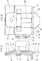
- Fig. 5 in vergrösserter Darstellung eine Draufsicht auf das die Führungshülse für die Kohlebürste aufnehmende Tragteil, und zwar bei strichpunktiert angedeutetem Deckel,
- Fig. 6 den Schnitt nach der Linie VI-VI in Fig. 5,
- Fig. 7 den Schnitt nach der Linie VII-VII in Fig. 5,
- Fig. 8 den Schnitt nach der Linie VIII-VIII in Fig. 5
- Fig. 9 in stark vergrösserter Darstellung einen Querschnitt durch die Steckverteilerplatte im Bereich eines dieser zugeordneten Anschlußsteckers und
- Fig. 10 eine klappfigürliche Ansicht der Fig. 9.
- Der Elektromotor besitzt ein Motorchassis 1. Dieses enthält eine Statorwicklung 2, welche einen nicht dargestellten Rotor umgibt. An letzterem sitzt ein Kollektor 3. Das über diesen vorstehende eine Ende der nicht dargestellten Rotorwelle läuft in einem Lager 4 einer diametral verlaufenden Brücke 5 des Motorchassis 1.
- Beiderseits des Kollektors 3 nimmt die Brücke 5 untereinander gleich ausgebildete Bürstenhalterungen 6 auf.
- Jede Bürstenhalterung 6 enthält ein aus isolierendem Material bestehendes, im Querschnitt U-förmiges Tragteil 7. Von dem Steg 8 des Tragteils 7 gehen sich über die ganze Länge des Steges erstreckende Seitenwände 9 und 10 aus. Die Innenflächen der Seitenwände formen am dem Steg 8 benachbarten Ende einem Einlagerungsabschnitt 12 vorgeordnete Einlaufschrägen 11, welcher Einlagerungsabschnitt 12 teilweise eine aus leitendem Material bestehende Führungshülse 13 umgreift. Innenseitig ist der Steg 8 mit endständigen Erhöhungen 14 versehen, auf welchen die Führungshülse 13 aufliegt, vergl. insbesondere Fig. 6.
- Die Führungshülse 13 besitzt ein im wesentlichen rechteckiges Querschnittsprofil zur Aufnahme der entsprechend querschnittsproflierten Kohlebürste 15. Im mittleren Bereich bildet das Rechteckprofil der Führungshülse 13 durch sich gegenüberliegende Ausbauchungen 16 einen Kreisquerschnitt zur Führung einer die Kohlebürste 15 belastenden Druckfeder 17.
- Um zu verhindern, dass nach Abnutzung der Kohlebürste 15 die Druckfeder an dem Kollektor 3 schleift, setzen die Ausbauchungen 16 jenseits eines querschnittskleineren Abschnitts 18 am vorderen Ende der Führungshülse 13 an. Die Druckfeder 17 überfängt einen Absatz 15' der Kohlebürste 15 und stützt sich mit einem Ende an der zwischen Kohlebürste 15 und Absatz 15' gebildeten Schulter ab. Das andere Ende der Druckfeder 17 findet Abstützung an einwärts gewinkelten Lappen 19 am rückwärtigen Ende der Führungshülse 13. Von der Kohlebürste 15 geht ein nach rückwärts gerichtetes Kupferseil aus, welches mittels einer Klemme 21 mit dem einen Anschlussende 23 einer Entstördrossel 24 verbunden ist. Das hintere Ende der Führungshülse 13 setzt sich in eine Anschlussfahne 22 fort, die zusätzlich das Anschlussende 23 der Entstördrossel 24 mit dem Ende des Zugseils 20 verbindet und diese Enden fixiert, vergl. Fig. 6.
- Die mit den Ausbauchungen 16 versehenen Seitenwände der als ringsgeschlossener Schacht ausgebildeten Führungshülse 13 sind mit auswärts gerichteten Fortsätzen 25 bestückt. Diese sind durch Herausdrücken erzeugt und ragen in vertikal zum Steg 8 des Tragteils 7 ausgerichtete Rillen 26 der Innenflächen der Seitenwände 9,10. Dadurch erhält die sich über die Länge des Tragteils 7 erstreckende Führungshülse 13 eine Lagenfixierung in Achsrichtung.
- Die Führungshülse 13 ist aus einem Stück geboten, wobei die Randkanten 27, wie aus Fig. 5 ersichtlich, schwalbenschwanzförmig ineinandergreifen.
- Die von oben zwischen die Seitenwände 9, 10 spielfrei eingesteckte Führungshülse 13 wird in ihrer Lage durch einen Deckel 28 gesichert. Dieser stützt sich mit seiner Unterseite an Längsaussparungen 29 derfreien Randkanten der Seitenwände 9, 10 ab. Der Deckel 28 weist zwei formpassend zwischen die Seitenwände 9, 10 ragende Stege 30 auf, die den dem Steg 8 gegenüberliegenden rechteckige Abschnitt der Führungshülse 13 spielfrei übergreifen, vergl. Fig. 8. Der Deckel 28 kann mit den Seitenwänden 9,10 verklebt, verschweisst oder in geeigneter Weise verbunden sein. Auf diese Weise ist die Führungshülse 13 in dem Tragteil 7 schwingungsfrei fixiert. Der Deckel 28 enthält zwei in Fig. 5 strichpunktiert dargestellte Durchbrechungen 31.
- Die Oberseite des Steges 7 trägt im mittleren Bereich einen Zentriervorsprung 32, wobei an der Übergangsstelle zwischen Oberseite und Zentriervorsprung 32 ein Kragen 33 angeformt ist.
- Der Steg 8 des Tragteils 7 ist mit nach auswärts über die Seitenwände 9, 10 vorstehenden Flügeln 34, 35 ausgestattet derart, dass der Flügel 34 mit Abstand vor dem rückwärtigen Ende des Tragteils 7 endet, vergl. insbesondere Fig. 4 und 5. Randseitig sind in den Flügeln 34, 35, dem vorderen Ende des Tragteils 7 benachbart, Aussparungen 36 angeordnet.
- Das Tragteil 7 enthält im rückwärtign Bereich beiderseits der Seitenwände 9, 10 Öffnungen 37 bzw. 38. Die Öffnung 37 wird von einem von der Seitenwand 9 materialeinheitlich ausgehenden, ein Klemmaul bildenden, winkelförmigen Rastarm 39 geformt. Ein endseitiger, mit einer Auflaufschräge 39' versehener Nocken 39" stellt in Verbindung mit weiteren Stegen 40, 41 eine Dreipunktauflage für die Entstördrossel 24 dar.
- Die andere Öffnung 38 ist einer Steckverteilerplatte 42 zugeordnet. Diese tritt mit einem Stecker 43 in die Öffnung 38 ein. Eine freigeschnittene, ausgebogene Rastnase 44 hintergreift in der eingeschobenen Stellung eine Schulter 45 der Öffnung 38, vergl. Fig. 7. Die Öffnung 38 befindet sich neben der einen Seitenwand 10, die somit zur Anlage der Steckverteilerplatte 42 dient. Die Seitennwand 10 ist mit einem den Deckel 28 überragenden Lappen 46 ausgebildet, der sich seinerseits in einen Haltevorsprung 47 fortsetzt, welcher eine Öffnung 48 im Knickbereich 49 einer von der Steckverteilerplatte 42 in Richtung der Entstördrossel 24 abgewinkelten Anschlussfahne 50 durchgreift. Diese ist mit dem anderen Anschlussende 23' der Entstördrossel 24 durch Umklammerung verbunden.
- Von der Steckverteilerplatte 42 geht eine quer zur Steckereinführungsrichtung abgebogene Kante 51 aus, die klemmend in einen Schacht 52 des Tragteils 7 eintaucht. Dieser Schacht 52 ist Bestandteil des den Deckel 28 übergreifenden Lappens 46.
- Das der Kante 51 gegenüberliegende Ende der Steckverteilerplatte 42 ist zu einer Abwinklung 53 abgebogen. In dieser befinden sich Einführöffnungen 54 und 55 für Flachstecker 56. Auf Höhe der Einführöffnungen sind durch Freischneiden und Herausdrücken Bügel 57 erzielt. Ein der Steckverteilerplatte 42 zugeordneter Flachstecker 56 erhält demgemäss eine Dreipunktabstützung, wobei die zwei äusseren Punkte A und B als Auflagepunkte und der Punkt C am Bügel 57 als Kraft angesehen werden können. Die Kraft wird dadurch erzeugt, dass die Federeigenschaft des handelsüblichen Steckers 56 ausgenutzt wird, und zwar durch entsprechende Lage des Auflagepunktes B, zum Punkt C. Wird ein Flachstecker 56 durch die Einführöffnung 54 bzw. 55 eingesteckt, durchsetzt er den entsprechenden Bügel 57. Danach trifft die Spitze 56' des Flachsteckers auf die eine AuflauffTache bildende Kante 51, wo der Auflagepunkt B nur noch um Materialstärke des Flachsteckers unter dem Gegenkraftpunkt C liegt. Bei der weiteren Einschubbewegung beginnt die Verformung des Flachsteckers 56 einhergehend mit einem Verbiegen unter Herstellung einer Nachspannreserve. Diese Kraft ist je nach Auslegung des Winkels der Kante 51 unterschiedlich. Der Einschub des Flachsteckers 56 wird durch beidseitige Anschläge 56" begrenzt, die gegen den seitlich der Einführöffnung 54 bzw. 55 vorhandenen Materialbereich der Steckverteilerplatte 42 stossen. Gleichzeitig ist eine Rastnase 56"' des Flachsteckers vor die Innenfläche der Abwinklung 53 getreten und stellt eine Abzugssicherung dar, siehe insbesondere Fig. 9.
- Um eine Deformierung des Steckers 43 der Steckverteilerplatte 42 auszuschliessen, stehen beiderseits der Öffnung 38 vom Steg 8 ausgehende Lappen 58 vor, die sich über die Länge des Steckers 43 erstrecken.
- Das Einsetzen der fertig montierten Bürstenhalterung 6 geschieht derart, dass das Tragteil 7 von oben her in eine Ausnehmung 59 der Brücke 5 eingeführt wird. Zwei sich gegenüberliegende Rippen 60 der Brücke 5 des Motorchassis 1 tauchen formschlüssig in die Aussparungen 36 der Flügel 34, 35 ein. Die Einsteckbewegung wird begrenzt durch Schultern 61 der Brücke 5, gegen welche die Auflageflächen bildenden Flügel 34, 35 stossen. Es kann nun eine gebogene, sich an der Oberseite des Steges 8 abstützende Blattfeder 62 angebracht werden. Dieselbe ist mit einer mittigen Öffnung 63 versehen, in die der Zentriervorsprung 32 eingreift. Unter gleichzeitigem Drücken und Verdrehen der Blattfeder 62 können deren Enden 62' Halteschultern 64 der Brücke 5 untergreifen. Die Blattfeder 62 liegt dabei mit ihrer Krümmung auf der Oberseite bzw. dem Kragen 33 des Steges 8 auf. Zum erleichterten Einführen der Blattfeder 62 bildet diese an diagonal gegenüberliegenden Ecken durch Abwinklung erzielte Auflaufschrägen 65 aus.
Claims (12)
Priority Applications (1)
| Application Number | Priority Date | Filing Date | Title |
|---|---|---|---|
| AT83102120T ATE15421T1 (de) | 1982-06-03 | 1983-03-04 | Buerstenhalterung an mit entstoerdrossel ausgestatteten elektromotoren, insbesondere fuer haushaltsgeraete wie staubsauger oder dergleichen. |
Applications Claiming Priority (2)
| Application Number | Priority Date | Filing Date | Title |
|---|---|---|---|
| DE19823220877 DE3220877A1 (de) | 1982-06-03 | 1982-06-03 | Buerstenhalterung an mit entstoerdrossel ausgestatteten elektromotoren, insbesondere fuer haushaltsgeraete wie staubsauger oder dergleichen |
| DE3220877 | 1982-06-03 |
Publications (2)
| Publication Number | Publication Date |
|---|---|
| EP0096158A1 EP0096158A1 (de) | 1983-12-21 |
| EP0096158B1 true EP0096158B1 (de) | 1985-09-04 |
Family
ID=6165182
Family Applications (1)
| Application Number | Title | Priority Date | Filing Date |
|---|---|---|---|
| EP83102120A Expired EP0096158B1 (de) | 1982-06-03 | 1983-03-04 | Bürstenhalterung an mit Entstördrossel ausgestatteten Elektromotoren, insbesondere für Haushaltsgeräte wie Staubsauger oder dergleichen |
Country Status (5)
| Country | Link |
|---|---|
| US (1) | US4550268A (de) |
| EP (1) | EP0096158B1 (de) |
| AT (1) | ATE15421T1 (de) |
| DE (2) | DE3220877A1 (de) |
| ES (1) | ES521090A0 (de) |
Families Citing this family (17)
| Publication number | Priority date | Publication date | Assignee | Title |
|---|---|---|---|---|
| JPS62124292U (de) * | 1986-01-30 | 1987-08-07 | ||
| US4777395A (en) * | 1986-03-31 | 1988-10-11 | Ametek, Inc. | Commutator end bracket |
| DE3635067C2 (de) * | 1986-10-15 | 1998-07-16 | Bosch Gmbh Robert | Reihenschluß-Kommutatormaschine |
| NL8701260A (nl) * | 1987-05-27 | 1988-12-16 | Philips Nv | Collectormachine. |
| US5182848A (en) * | 1987-07-24 | 1993-02-02 | Black & Decker Inc. | Method for assembling a stator subassembly |
| US4885496A (en) * | 1987-07-24 | 1989-12-05 | Black & Decker Inc. | Stator end member and assemblies therewith and methods of assembly |
| US5231321A (en) * | 1989-08-28 | 1993-07-27 | Asmo Co., Ltd. | Noise preventing arrangement of a motor |
| DE59202257D1 (de) * | 1992-09-07 | 1995-06-22 | Siemens Ag | Geräuschgedämpfte Bürstenhalterung, insbesondere für einen Kommutator-Kleinmotor. |
| US5465016A (en) * | 1993-09-08 | 1995-11-07 | Electrolux Corporation | Electric motor and brush/shunt assembly therefor |
| TR28171A (tr) * | 1993-09-15 | 1996-02-29 | Siemens Ag | Az gürültülü komütatör motor tahriki icin kullanilabilen firca destegi. |
| DE19717594B4 (de) * | 1997-04-25 | 2017-09-07 | BSH Hausgeräte GmbH | Bürstenanordnung an einer elektrischen Maschine |
| US6078117A (en) * | 1997-08-27 | 2000-06-20 | Nartron Corporation | End cap assembly and electrical motor utilizing same |
| JP3639131B2 (ja) * | 1998-06-05 | 2005-04-20 | アスモ株式会社 | 直流モータの電気ノイズ防止器 |
| DE10362027B4 (de) * | 2003-07-09 | 2006-06-14 | Siemens Ag | Fördereinheit |
| US7518274B1 (en) | 2006-06-12 | 2009-04-14 | Mancl Dennis J | Motor bracket with integral terminals |
| BR102017028396B1 (pt) * | 2017-12-28 | 2023-02-14 | Robert Bosch Limitada | Estrutura de suporte de contatos elétricos e motor elétrico universal provido de estrutura de suporte de contatos elétricos |
| CN109450195B (zh) * | 2018-12-05 | 2020-05-01 | 南京涵曦月自动化科技有限公司 | 一种用于大中型绕线电动机的外接注粉抽离的接碳粉装置 |
Family Cites Families (10)
| Publication number | Priority date | Publication date | Assignee | Title |
|---|---|---|---|---|
| US1132304A (en) * | 1912-12-21 | 1915-03-16 | Splitdorf Electrical Co | Brush-holder and terminal for connecting electric cable. |
| US2334722A (en) * | 1941-06-26 | 1943-11-23 | Carlos B Mirick | Suppressor condenser integral with brush holder |
| DE1588975A1 (de) * | 1966-02-24 | 1970-05-21 | Electrolux Ab | Buerstenhalter fuer elektrische Kommutatormotoren |
| US3842302A (en) * | 1973-05-21 | 1974-10-15 | Ford Motor Co | Electrical snap-in terminal and brush housing and method of assembly |
| DE2831928A1 (de) * | 1978-07-20 | 1980-03-20 | Bosch Gmbh Robert | Buerstenhalter fuer kleine kommutator-motoren, insbesondere fuer heimwerker-kombinationsmaschinen |
| DE2914853A1 (de) * | 1979-04-12 | 1980-10-30 | Bosch Gmbh Robert | Elektrische kleinmaschine, insbesondere kleinmotor |
| US4266155A (en) * | 1979-09-10 | 1981-05-05 | The Singer Company | Brush holder assembly |
| DE3168621D1 (en) * | 1980-07-11 | 1985-03-14 | Shop Vac Corp | Electric motor brush holder |
| US4329605A (en) * | 1980-10-14 | 1982-05-11 | General Motors Corporation | Electric motor having radio frequency interference radiation suppression |
| US4389588A (en) * | 1982-03-24 | 1983-06-21 | Alexander Rankin | Current carrying constant force brush holder assembly |
-
1982
- 1982-06-03 DE DE19823220877 patent/DE3220877A1/de not_active Withdrawn
-
1983
- 1983-03-04 AT AT83102120T patent/ATE15421T1/de not_active IP Right Cessation
- 1983-03-04 EP EP83102120A patent/EP0096158B1/de not_active Expired
- 1983-03-04 DE DE8383102120T patent/DE3360700D1/de not_active Expired
- 1983-03-29 ES ES521090A patent/ES521090A0/es active Granted
- 1983-05-27 US US06/499,092 patent/US4550268A/en not_active Expired - Fee Related
Also Published As
| Publication number | Publication date |
|---|---|
| EP0096158A1 (de) | 1983-12-21 |
| DE3360700D1 (en) | 1985-10-10 |
| ATE15421T1 (de) | 1985-09-15 |
| US4550268A (en) | 1985-10-29 |
| ES8401813A1 (es) | 1984-01-01 |
| DE3220877A1 (de) | 1983-12-08 |
| ES521090A0 (es) | 1984-01-01 |
Similar Documents
| Publication | Publication Date | Title |
|---|---|---|
| EP0096158A1 (de) | Bürstenhalterung an mit Entstördrossel ausgestatteten Elektromotoren, insbesondere für Haushaltsgeräte wie Staubsauger oder dergleichen | |
| EP1257018B1 (de) | Elektrischer Steckadapter | |
| DE2831928C2 (de) | ||
| DE102018102976A1 (de) | Drahthalter | |
| DE2920460C3 (de) | Leuchtenanordnung an einem Schaltungsbrett eines Instrumententrägers | |
| DE3224954A1 (de) | Steckkarten-sockel | |
| DE10300723A1 (de) | Sammelschienensystem und Anschluss- oder Geräte-Adapter | |
| DE19524381C2 (de) | Installationskanal mit einem zu einer Seite offenen metallischen Kanalprofil | |
| EP0684670A2 (de) | Bürstenhalter | |
| DE4205974C1 (en) | Electrical plug connector with built-in latching for pins - provides section formed on housing that locates against pin flange and is held by latch stage | |
| DE19717594B4 (de) | Bürstenanordnung an einer elektrischen Maschine | |
| DD248682A1 (de) | Anordnung zur herstellung von elektrischen verbindungen in einem elektromotor | |
| DE69618921T2 (de) | Verbinder mit drahtabdichtenden Rippen | |
| DE102022127804A1 (de) | Anschlussanordnung und Anschlussklemme | |
| EP0612136B1 (de) | Bürstenhalteranordnung für einen Kommutatormotor | |
| DE9102340U1 (de) | Tragplatte, insbesondere Bürsten-Tragplatte | |
| DE3538942A1 (de) | Feldstecker fuer einen elektromotor | |
| DE102020121004A1 (de) | Kontaktelement und Anschlusselement | |
| DE2704057C2 (de) | Elektrisches Installationsgerät, insbesondere Steckdose | |
| DE8510201U1 (de) | Katheterset | |
| DE202019102309U1 (de) | Transformatorklemme | |
| EP0105538A1 (de) | Steckdose oder Steckerleiste aus Kunststoff | |
| DE202018107195U1 (de) | Direktsteckverbinder für eine Leiterplatte | |
| DE8227502U1 (de) | Am staenderblechpaket einer elektrischen kleinmaschine festlegbare verbindungs-vorrichtung | |
| DE8010402U1 (de) | Halter für elektrotechnische Bauteile mit stirnseitigen Kontaktflächen |
Legal Events
| Date | Code | Title | Description |
|---|---|---|---|
| PUAI | Public reference made under article 153(3) epc to a published international application that has entered the european phase |
Free format text: ORIGINAL CODE: 0009012 |
|
| AK | Designated contracting states |
Designated state(s): AT BE CH DE FR GB IT LI LU NL SE |
|
| 17P | Request for examination filed |
Effective date: 19831108 |
|
| ITF | It: translation for a ep patent filed | ||
| GRAA | (expected) grant |
Free format text: ORIGINAL CODE: 0009210 |
|
| AK | Designated contracting states |
Designated state(s): AT BE CH DE FR GB IT LI LU NL SE |
|
| REF | Corresponds to: |
Ref document number: 15421 Country of ref document: AT Date of ref document: 19850915 Kind code of ref document: T |
|
| REF | Corresponds to: |
Ref document number: 3360700 Country of ref document: DE Date of ref document: 19851010 |
|
| ET | Fr: translation filed | ||
| PLBE | No opposition filed within time limit |
Free format text: ORIGINAL CODE: 0009261 |
|
| STAA | Information on the status of an ep patent application or granted ep patent |
Free format text: STATUS: NO OPPOSITION FILED WITHIN TIME LIMIT |
|
| 26N | No opposition filed | ||
| ITTA | It: last paid annual fee | ||
| EPTA | Lu: last paid annual fee | ||
| EAL | Se: european patent in force in sweden |
Ref document number: 83102120.9 |
|
| PGFP | Annual fee paid to national office [announced via postgrant information from national office to epo] |
Ref country code: FR Payment date: 19970218 Year of fee payment: 15 Ref country code: AT Payment date: 19970218 Year of fee payment: 15 |
|
| PGFP | Annual fee paid to national office [announced via postgrant information from national office to epo] |
Ref country code: CH Payment date: 19970219 Year of fee payment: 15 |
|
| PGFP | Annual fee paid to national office [announced via postgrant information from national office to epo] |
Ref country code: GB Payment date: 19970224 Year of fee payment: 15 |
|
| PGFP | Annual fee paid to national office [announced via postgrant information from national office to epo] |
Ref country code: DE Payment date: 19970304 Year of fee payment: 15 |
|
| PGFP | Annual fee paid to national office [announced via postgrant information from national office to epo] |
Ref country code: SE Payment date: 19970319 Year of fee payment: 15 |
|
| PGFP | Annual fee paid to national office [announced via postgrant information from national office to epo] |
Ref country code: LU Payment date: 19970325 Year of fee payment: 15 |
|
| PGFP | Annual fee paid to national office [announced via postgrant information from national office to epo] |
Ref country code: NL Payment date: 19970331 Year of fee payment: 15 |
|
| PGFP | Annual fee paid to national office [announced via postgrant information from national office to epo] |
Ref country code: BE Payment date: 19970521 Year of fee payment: 15 |
|
| PG25 | Lapsed in a contracting state [announced via postgrant information from national office to epo] |
Ref country code: LU Free format text: LAPSE BECAUSE OF NON-PAYMENT OF DUE FEES Effective date: 19980304 Ref country code: GB Free format text: LAPSE BECAUSE OF NON-PAYMENT OF DUE FEES Effective date: 19980304 Ref country code: AT Free format text: LAPSE BECAUSE OF NON-PAYMENT OF DUE FEES Effective date: 19980304 |
|
| PG25 | Lapsed in a contracting state [announced via postgrant information from national office to epo] |
Ref country code: SE Free format text: LAPSE BECAUSE OF NON-PAYMENT OF DUE FEES Effective date: 19980305 |
|
| PG25 | Lapsed in a contracting state [announced via postgrant information from national office to epo] |
Ref country code: LI Free format text: LAPSE BECAUSE OF NON-PAYMENT OF DUE FEES Effective date: 19980331 Ref country code: FR Free format text: THE PATENT HAS BEEN ANNULLED BY A DECISION OF A NATIONAL AUTHORITY Effective date: 19980331 Ref country code: CH Free format text: LAPSE BECAUSE OF NON-PAYMENT OF DUE FEES Effective date: 19980331 Ref country code: BE Free format text: LAPSE BECAUSE OF NON-PAYMENT OF DUE FEES Effective date: 19980331 |
|
| BERE | Be: lapsed |
Owner name: VORWERK & CO. INTERHOLDING G.M.B.H. Effective date: 19980331 |
|
| PG25 | Lapsed in a contracting state [announced via postgrant information from national office to epo] |
Ref country code: NL Free format text: LAPSE BECAUSE OF NON-PAYMENT OF DUE FEES Effective date: 19981001 |
|
| GBPC | Gb: european patent ceased through non-payment of renewal fee |
Effective date: 19980304 |
|
| REG | Reference to a national code |
Ref country code: CH Ref legal event code: PL |
|
| NLV4 | Nl: lapsed or anulled due to non-payment of the annual fee |
Effective date: 19981001 |
|
| PG25 | Lapsed in a contracting state [announced via postgrant information from national office to epo] |
Ref country code: DE Free format text: LAPSE BECAUSE OF NON-PAYMENT OF DUE FEES Effective date: 19981201 |
|
| EUG | Se: european patent has lapsed |
Ref document number: 83102120.9 |
|
| REG | Reference to a national code |
Ref country code: FR Ref legal event code: ST |