EP0096097B1 - Method and apparatus for controlling access to a communication network - Google Patents
Method and apparatus for controlling access to a communication network Download PDFInfo
- Publication number
- EP0096097B1 EP0096097B1 EP82105211A EP82105211A EP0096097B1 EP 0096097 B1 EP0096097 B1 EP 0096097B1 EP 82105211 A EP82105211 A EP 82105211A EP 82105211 A EP82105211 A EP 82105211A EP 0096097 B1 EP0096097 B1 EP 0096097B1
- Authority
- EP
- European Patent Office
- Prior art keywords
- node
- bus
- bus segment
- segment
- message
- Prior art date
- Legal status (The legal status is an assumption and is not a legal conclusion. Google has not performed a legal analysis and makes no representation as to the accuracy of the status listed.)
- Expired
Links
- 238000000034 method Methods 0.000 title claims description 18
- 230000006854 communication Effects 0.000 title claims description 13
- 238000004891 communication Methods 0.000 title claims description 13
- 230000004913 activation Effects 0.000 claims description 15
- 238000012546 transfer Methods 0.000 claims description 14
- 230000005540 biological transmission Effects 0.000 claims description 8
- 230000002457 bidirectional effect Effects 0.000 claims description 5
- 230000000694 effects Effects 0.000 claims description 4
- 238000013475 authorization Methods 0.000 claims 4
- 230000002401 inhibitory effect Effects 0.000 claims 1
- 230000001172 regenerating effect Effects 0.000 claims 1
- 230000003213 activating effect Effects 0.000 description 5
- 238000010586 diagram Methods 0.000 description 5
- 238000003780 insertion Methods 0.000 description 4
- 230000037431 insertion Effects 0.000 description 4
- 101100172132 Mus musculus Eif3a gene Proteins 0.000 description 3
- 239000002609 medium Substances 0.000 description 3
- 230000004048 modification Effects 0.000 description 3
- 238000012986 modification Methods 0.000 description 3
- 230000000644 propagated effect Effects 0.000 description 3
- 230000001105 regulatory effect Effects 0.000 description 2
- 230000004044 response Effects 0.000 description 2
- 230000007175 bidirectional communication Effects 0.000 description 1
- 238000006243 chemical reaction Methods 0.000 description 1
- 238000005352 clarification Methods 0.000 description 1
- 230000001934 delay Effects 0.000 description 1
- 230000003111 delayed effect Effects 0.000 description 1
- 230000001419 dependent effect Effects 0.000 description 1
- 238000013461 design Methods 0.000 description 1
- 238000001514 detection method Methods 0.000 description 1
- 230000007246 mechanism Effects 0.000 description 1
- 239000006163 transport media Substances 0.000 description 1
Images
Classifications
-
- H—ELECTRICITY
- H04—ELECTRIC COMMUNICATION TECHNIQUE
- H04L—TRANSMISSION OF DIGITAL INFORMATION, e.g. TELEGRAPHIC COMMUNICATION
- H04L12/00—Data switching networks
- H04L12/28—Data switching networks characterised by path configuration, e.g. LAN [Local Area Networks] or WAN [Wide Area Networks]
- H04L12/46—Interconnection of networks
- H04L12/4604—LAN interconnection over a backbone network, e.g. Internet, Frame Relay
- H04L12/462—LAN interconnection over a bridge based backbone
Definitions
- Present invention is concerned with a communication system comprising several interconnected bus segments to which stations are attached.
- Such networks are particularly suited for local area communication facilities which interconnect data stations located within a building or in a restricted area.
- bus segments are permanently interconnected by bidirectional repeaters, and all attached stations can communicate with each other. They contend for access to the bus segments, i.e. the transmission medium, in a specific procedure.
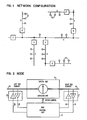
- Fig. 1 shows the configuration of a local network in which the inventin finds application. It comprises a plurality of bus segments A, B, C, D, E, F, G which are interconnected by node units 1, 2, 3, 4, 5, 6, 7. A number of stations ST are connected to each bus segment.
- Each bus segment is a bidirectional communication line, e.g. a coaxial cable, comprising outlets or taps at which stations or node units can be attached.
- Each node unit comprises unidirectional amplifier means (repeater/regenerator) and switches for selectively connecting the amplifier means so that it either transfers messages from a first to a second bus segment attached to the node, or vice versa from the second to the first bus segment.
- the two bus segments attached to a node unit will be called the "right bus segment" and the "left bus segment", respectively.
- the basic idea of the invention is that in the whole network, only one node unit and one bus segment are "active" at a time.
- the active node e.g. node 3
- Amplifiers in all nodes are switched in such a way that messages transmitted from stations attached to the presently active segment can propagate to all stations in the network.
- the activity status is passed in a predetermined sequence from node to node by a token message.
- the assigned node unit e.g. node 3
- the assigned node unit sends a token message to its successor node (e.g. node 4) which then becomes the active node whereas the token sender (after disactivating its bus segment) is disactivated.
- the newly activated node i.e. node 4
- setting of the repeater switches in the nodes involved is updated so that always the messages originating at the currently active bus segment can pass through the network to all stations at all other bus segments.
- a node comprises a switch and repeater unit 11 which can be set to either transfer messages from "right" bus segment 13 to "left” bus segment 15, or from the left to the right bus segment, but which can also be set to an isolate state interrupting any transfer between the two bus segments.
- a node further comprises a control unit 17 which can store token route information (successor, predecessor addresses etc.), which evaluates received information, which develops switch control signals and which can transmit TOKEN, ACKNOWLEDGE, ACTIVATE, and DISACTIVATE messages.
- a node control unit is connected to both attached bus segments for receiving information on a right bus-in 19 and a left bus-in 21 and for transmitting information on a right bus-out 23 and a left bus-out 25.
- Right bus-in 19 and right bus-out 23 are connected to right bus segment 13 through a receiver R and a transmitter T in first connecting circuitry 27.
- Left bus-in 21 and left bus-out 25 are connected to left bus segment 15 through a receiver R and a transmitter T in second connecting circuitry 29.
- switch and repeater unit 11 and of node control unit 17 will be shown and explained in connection with Figs. 3 and 4.
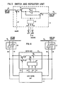
- Fig. 3 shows in a block diagram the main elements of switch and repeater unit 11 of a node. It comprises a unidirectional repeater or amplifier 31 which can be connected between right bus segment 13 and left bus segment 15 in either one of the two possible directions by parallel-operated switches 33 and 35. Control signals for these switches are furnished by switch control 37 which contains a bistable circuit that in turn can be set, reset or reversed by three different control signals from the node control unit on lines 39, 41 and 43: "set to left", “set to right", and "reverse". It should be noted that a direct connection between switches 33 and 35 is never possible. They are always separated by amplifier 31.
- An isolating switch 45 is also provided. It is controlled by an "isolate" signal on line 47 from the node control unit. By this switch 45, the right and left bus segment can be completely isolated from each other without changing the position of switches 33 and 35.
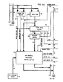
- Fig. 4 is a block diagram of the main elements of node control unit 17.
- Message type decoder 51 is connected to right bus-in lines 19 and also to left bus-in lines 21 to receive each message propagated on both bus segments which are connected to the respective node unit. It activates a control signal on line 53 when a TOKEN message was received having as destination address the node's own address.
- a control signal on line 55 is activated after reception of an ACKNOWLEDGE message from another node, and a control signal on line 57 is activated when an ACTIVATE message was received from another node.
- the origin address of each message is stored in register 59 and will be available on lines 61 if the token/own address signal on line 53 is active.
- Token route section 63 comprises two registers each having following fields:
- the respective node When the respective node receives a token from the predecessor identified in (a), the three bits in fields (b), (c) and (d) determine whether the bus segment assigned to the respective node must be activated, and when thereafter the token is forwarded to the successor node whose address is given in (e), how the switches have to be set (left or right) when the node is deactivated.
- the registers are loaded when the respective node is inserted into the system, or when its neighbour nodes (predecessor or successor) are changed.
- the signal on line 53 will activate token route section 63 to use the token origin address on lines 61 to read out the register having this origin as predecessor address, and to furnish the contents of fields (b), (c), (d) and (e) on lines 65, 67, 69 and 71, respectively.
- the signals on lines 67 and 69 will either set or reset a switch preselect flipflop 73.
- the address on lines 71 is loaded into successor address register 75.
- Block 77 is the node activate/disactivate control section. It receives the "token/own address received” signal on line 53, the "acknowledgement received” signal on line 55, the “activate segment received” signal on line 65, and a “transmit token” signal on line 79. Its further inputs are the origin address lines 61 and the successor address lines 81. Its data output lines are connected to right bus-out 23 as well as to left bus-out 25. Control output lines are a line 83 for an indicator signal "node not active", a line 85 for a control signal “gate switch control”, and a line 86 for a control signal "isolate switch".
- node activate/disactivate control section 77 Functions of node activate/disactivate control section 77 are as follows: When the token/own address indicator signal (line 53) becomes active, the "node not active" signal on line 83 is disactivated, and an ACKNOWLEDGE message, using as destination address the origin address on lines 61, is furnished to the bus-out lines (23 and 25). Simultaneously, the signal "isolate switch" on line 86 is raised. If, thereafter, the "active segment” signal on line 65 is not raised within an given time, or if the signal "transmit token” on line 79 is activated, a TOKEN message using as destination address the successor address on lines 81 will be furnished to the bus-out lines (23 and 25).
- the "isolate switch” signal on line 86 is raised again. If, thereafter, the "acknowledgement received” signal is raised on line 55, the "gate switch control” signal is activated on line 85 to operate gates 87 and 89 for the switch control signals. Simultaneously, the signal “node not active” on line 83 is raised again.
- the token message will be repeated several times (e.g. three times) if no acknowledgement is received within a given time limit, and thereafter, an alternate successor address on line 91 which was previously loaded into register 93 may be used as token address. Alternatively, an appropriate error message may be transmitted to a network service center without issuing a token.
- Block 95 is a segment activate/disactivate section. It receives the "active segment” signal on line 65, and a “transmit disactivate” signal from an AND gate 97 (if an ACTIVATE message is received when the respective node is not active). It further receives a delayed "silence” signal on line 99 from a signal detector 101 which is connected to the own (assigned) bus segment 13 via right bus-in lines 19. The main output of this section is connected to right bus-out 23 for furnishing messages to the own (right) bus segment 13. It has further output lines 43,103 and 79 for control signals "reverse switch", “isolate switch”, and "transmit token", respectively.
- segment activate/disactivate section 95 Functions of segment activate/disactivate section 95 are as follows: When the signal "activate segment” on line 65 is raised, an ACTIVATE message is released on the right bus-out 23 for the own (right) bus segment 13. The "reverse switch” signal is then raised on line 43. If any time thereafter silence is indicated on line 99, or if the "transmit disactivate” signal is raised on the output line of AND gate 97, a DISACTIVATE message is released on the right bus-out 23 for the own (right) bus segment 13.
- the ACTIVATE message enables all stations which receive it to contend for access to the bus segment to which they are attached.
- the DISACTIVATE message disables all stations receiving it.
- the switch and repeater unit 11 and the control and transmission lines connected to it are the same as those shown in Fig. 2.
- the "isolate" signal on line 47 is furnished by an OR gate 105 which has its inputs connected to "isolate switch” lines 86 and 103.
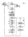
- each node is initialized and the switches set to a home position, e.g. the position transferring messages towards its own, assigned bus segment (by definition, this segment is called the right bus segment and the respective switch position the right position). This ensures that all messages properly propagate through the whole network after initialization.
- each node watches whether it receives an ACTIVATE message (block 122) or a TOKEN message with its own address (block 124). Respective indicator signals will be furnished by message type decoder 51 (Fig. 4). If an ACTIVATE message is received but the node is not active, the node will immediately isolate its repeater and send a DISACTIVATE message to its own segment (block 123). This is done by segment activate/disactivate section 95 in response to a "transmit deactivate" signal from AND gate 97 (Fig. 4).
- the purpose of this operation is to ensure that an ACTIVATE message distributed by an active node does not result in the activation of bus segments assigned to other, currently inactive nodes; thus, only the own assigned bus segment of the active node is finally activated.
- the switches in inactive nodes are temporarily inhibited to avoid back-distribution of the DISACTIVATE message to the segment that actually should be activated.
- a node When a node receives a TOKEN message with its own address as destination (block 124), it immediately transmits an ACKNOWLEDGE message (block 126) addressed to the origin of the received token. This is done by node activate/disactivate control section 77, using the address in register 59. Thereafter, the origin address in register 59 is used to interrogate the token route information (block 128) for determining the successor address (next node to receive token), for preselecting the new switch setting, and for determining whether the bus segment assigned to the node is to be activated this time or not. All this information is obtained from a register in token route section 63. The successor address will be stored in register 75, the switch preselect information in flipflop 73.
- the node If the node must activate its assigned bus segment (block 130), it transmits an ACTIVATE message (block 132) to allow all stations connected to its bus segment to contend for bus access, and then reverses the setting of its switches, i.e. the transfer direction of its repeater (block 134) so that any message transmitted by any station on its bus segment can propagate to all bus segments on both sides of the active node, i.e. to all other parts of the network.
- all other nodes i.e. the inactive nodes, will destroy the effect of the ACTIVATE message for their own bus segment by immediately sending a DISACTIVATE message (block 123).
- the active node After transmitting the ACTIVATE message, the active node will watch its assigned bus segment for silence to occur for a given period of time, to determine when no station sends a message any more (block 136). In the meantime, all stations of the active bus segment had a chance to transmit, the access being regulated by any one of several known multiple-access techniques, e.g. CSMA/CD (carrier sense multiple access/collision detection).
- CSMA/CD carrier sense multiple access/collision detection
- the silence watch is done by signal detector 101, which reports the bus signal status to segment activate/disactivate section 95. Its "silence" output signal on line 99 is only raised when there was no signal on the bus segment for a given period of time.
- the active node gets access to its bus segment (block 138) and transmits a DISACTIVATE message on this bus segment (block 140) which will then be propagated over the whole network, to prepare forwarding of the token and changing of the node and bus segment active status.
- an active node When an active node disactivated the stations on its bus segment (or if it did not activate them at all), it transmits a TOKEN message to its successor node (block (142). This may be repeated a given number of times, e.g. three times if no acknowledgement is received (block 144) within a fixed time limit. The TOKEN message may finally be sent to an alternate successor if the regular successor node does not react at all (or an error message may be sent to a network service center).
- the node having forwarded the token will adjust the setting of its repeater switches (block 146) as indicated by the switch preselect flipflop so that subsequently, any messages transmitted on the next activated bus segment will be correctly propagated through the whole network.
- the node is then disactivated, i.e. it returns to block 122/block 124 to watch for the arrival of an ACTIVATE or TOKEN message.
- Sending of the DISACTIVATE message is effected by the segment activate/disactivate section 95 when the "silence" signal on line 99 is raised.
- Section 95 then also raises the "transmit token” signal on line 79 to node activate/disactivate control section 77 which handles the sending of a TOKEN message with a successor address taken from register 75 or, alternatively, from register 93.
- Control section 77 also effects the repetition of the token message until it receives an "acknowledge” indication. Thereafter, it raises the "gate switch control" signal on line 85 to have the switch preselect information from flipflop 73 be gated to the switch and repeater unit 11 for final setting of the switches as dictated by the information in token route section 63.
- node 1 When system operation is started, node 1 is initialized to be active. it then activates its assigned bus segment A for station contention. Thereafter, a regular cycle starts: The token is transferred to node 2 which activates its assigned bus segment B. This goes on as indicated in the table until node 5 is active and has activated bus segment E. The next bus segment to be activated is segment F, thus the token should be sent to node 6. However, as can be seen from Fig. 1, the token must pass through node 4 again on its way to node 6. Thus, node 4 is shortly activated, but only for forwarding the token and for adjusting its repeater switches, and not for activating its bus segment D this time. The switch adjustment is necessary because when the token was with node 5, switches of node 4 had to insure message transfer from segment D to A, whereas afterwards, when the token is with node 6, switches of node 4 have to direct messages from section A to section D.
- Node 4 now passes the token over to node 6 which will activate segment F, and the token then proceeds to node 7 for activating segment G. Thereafter, the token needs only to be routed back to node 1 through node 6 which is shortly activated without activating its assigned bus segment F this time.
- Table 3 The information shown in Table 3 is the same as that which is stored in the registers of the token route section 63 (Fig. 4) of each respective node.
- the predecessor is the node from which the respective node (indicated in the left-most column) receives a token
- the successor is the node to which it must forward the token afterwards.
- a plus or minus sign indicates whether the own assigned bus segment of the respective node must be activated or not.
- a "1" in the R column indicates that repeater switches must be set to the "right” direction (i.e. message transfers towards own bus segment) afterwards, and a "1" in L column indicates that repeater switches must forward messages to the "left" direction (i.e. away from own assigned bus segment) when the respective node is disactivated.
- a node at an end segment is only activated once during a cycle and has only one predecessor and successor, whereas a node within the network receives the token twice during a cycle and has two predecessors and two successors.
- New nodes may be inserted into the network at any segment, or old nodes may be removed. This requires, of course, an updating of the token route and thus of the token route information, i.e. the successor/predecessor assignments, in the neighbour nodes of the inserted or removed node.
- the only operation required for updating the token route is the reloading of registers in token route section 63 of the nodes involved (neighbour nodes) by network management at the time of insertion or removal of a node. It should be noted that insertion, removal, or moving of normal stations (ST in Fig. 1) is not to be confused with node insertion or removal, and is in no way restricted when the present invention is used in a system.
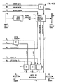
- FIG. 6 An alternative solution for switch and repeater unit 11 of Figs. 2 and 3 is shown in Fig. 6.
- node control unit 17 is connected through first and second connecting circuitry 27 and 29, respectively, to its right bus segment 13 and left bus segment 15.
- the alternative solution of Fig. 6 comprises only a switch unit 11' which does not contain an amplifier or repeater but only a few switches and associated control circuitry.
- This switch unit 11' is connected parallel to node control unit 17 between right bus-in 19, right bus-out 23 and left bus-in 21, left bus-out 25.
- Switch unit 11' comprises switch 107 for directly interconnecting left bus-in 21 and right bus-out 23, thus establishing a unidirectional, amplifying path from left bus segment 15 to right bus segment 13.
- Switch unit 11' further comprises switch 109 for directly interconnecting right bus-in 19 and left bus-out 25, thus establishing a unidirectional, amplifying path from right bus segment 13 to left bus segment 15. Only one of switches 107 and 109 is closed at any time, never both.
- switch control 37' which may be a bistable circuit with control inputs for set, reset, and reverse.
- Switches 45' and 45" are provided in series with switches 107 and 109, respectively, for completely isolating the right and left bus segment from each other. They are controlled by an "isolate" signal on line 47.
- control signals on lines 39,41,43, and 47 are all furnished by node control unit 17 in the same way as was explained in connection with Figs. 2 and 3.
- Fig. 6 provides the same functions as that of Figs. 2 and 3. It can selectively establish an amplifying connection between bus segments 13 and 15 in either direction, or it can isolate both from each other.
Landscapes
- Engineering & Computer Science (AREA)
- Computer Networks & Wireless Communication (AREA)
- Signal Processing (AREA)
- Small-Scale Networks (AREA)
Priority Applications (4)
| Application Number | Priority Date | Filing Date | Title |
|---|---|---|---|
| EP82105211A EP0096097B1 (en) | 1982-06-15 | 1982-06-15 | Method and apparatus for controlling access to a communication network |
| DE8282105211T DE3268099D1 (en) | 1982-06-15 | 1982-06-15 | Method and apparatus for controlling access to a communication network |
| US06/497,534 US4583088A (en) | 1982-06-15 | 1983-05-24 | Method and apparatus for controlling access to a communication network |
| JP58095119A JPS58223938A (ja) | 1982-06-15 | 1983-05-31 | 通信ネツトワ−ク呼出し制御方法 |
Applications Claiming Priority (1)
| Application Number | Priority Date | Filing Date | Title |
|---|---|---|---|
| EP82105211A EP0096097B1 (en) | 1982-06-15 | 1982-06-15 | Method and apparatus for controlling access to a communication network |
Publications (2)
| Publication Number | Publication Date |
|---|---|
| EP0096097A1 EP0096097A1 (en) | 1983-12-21 |
| EP0096097B1 true EP0096097B1 (en) | 1985-12-27 |
Family
ID=8189087
Family Applications (1)
| Application Number | Title | Priority Date | Filing Date |
|---|---|---|---|
| EP82105211A Expired EP0096097B1 (en) | 1982-06-15 | 1982-06-15 | Method and apparatus for controlling access to a communication network |
Country Status (4)
| Country | Link |
|---|---|
| US (1) | US4583088A (ja) |
| EP (1) | EP0096097B1 (ja) |
| JP (1) | JPS58223938A (ja) |
| DE (1) | DE3268099D1 (ja) |
Families Citing this family (34)
| Publication number | Priority date | Publication date | Assignee | Title |
|---|---|---|---|---|
| FR2552609B1 (fr) * | 1983-09-27 | 1985-10-25 | Cit Alcatel | Procede et dispositif de selection d'une station d'un ensemble de stations dialoguant avec une station principale |
| US4701908A (en) * | 1984-06-22 | 1987-10-20 | Canon Kabushiki Kaisha | Network system utilizing plural station addresses |
| FR2567345B1 (fr) * | 1984-07-04 | 1992-03-13 | Jeumont Schneider | Procede de determination du dernier noeud intermediaire dans un reseau de plusieurs noeuds interconnectes |
| JPS6133046A (ja) * | 1984-07-25 | 1986-02-15 | コ−デツクス・コ−ポレ−シヨン | 網形成回路 |
| US4882728A (en) * | 1984-07-25 | 1989-11-21 | Codex Corporation | Networking circuitry |
| JPH0630511B2 (ja) * | 1984-10-31 | 1994-04-20 | 株式会社日立製作所 | 局順可変の環状伝送システム |
| GB2175177B (en) * | 1985-05-17 | 1989-01-25 | Racal Data Communications Inc | Method and apparatus for interfacing a contention device to a token passing network |
| US4701630A (en) * | 1985-06-27 | 1987-10-20 | International Business Machines Corp. | Local area network station connector |
| JPH0632517B2 (ja) * | 1985-07-19 | 1994-04-27 | ホーチキ株式会社 | 異常監視装置 |
| US4667323A (en) * | 1985-09-03 | 1987-05-19 | Allen-Bradley Company, Inc. | Industrialized token passing network |
| US4682326A (en) * | 1985-11-27 | 1987-07-21 | General Electric Company | Method and apparatus for maintaining a dynamic logical ring in a token passing lan |
| US4763329A (en) * | 1986-02-10 | 1988-08-09 | Techlan, Inc. | Modular data routing system |
| US4771391A (en) * | 1986-07-21 | 1988-09-13 | International Business Machines Corporation | Adaptive packet length traffic control in a local area network |
| NO169801C (no) * | 1986-07-29 | 1992-08-05 | Siemens Ag | Koblingsanordning til seriell dataoverfoering. |
| US4747100A (en) * | 1986-08-11 | 1988-05-24 | Allen-Bradley Company, Inc. | Token passing network utilizing active node table |
| GB2194867B (en) * | 1986-09-09 | 1991-05-29 | Mitsubishi Electric Corp | A transmission line control system and method for disconnecting a sub-bus from a main-bus |
| FR2605768B1 (fr) * | 1986-10-23 | 1989-05-05 | Bull Sa | Dispositif de commande de bus constitue par plusieurs segments isolables |
| US4914657A (en) * | 1987-04-15 | 1990-04-03 | Allied-Signal Inc. | Operations controller for a fault tolerant multiple node processing system |
| AU604959B2 (en) * | 1987-05-01 | 1991-01-03 | Digital Equipment Corporation | Servicing interrupts using a pended bus |
| EP0358715B1 (en) * | 1987-05-01 | 1994-03-09 | Digital Equipment Corporation | Interrupting node for providing interrupt requests to a pended bus |
| US4953072A (en) * | 1987-05-01 | 1990-08-28 | Digital Equipment Corporation | Node for servicing interrupt request messages on a pended bus |
| JP2539457B2 (ja) * | 1987-10-02 | 1996-10-02 | 株式会社日立製作所 | リング集線装置 |
| US4850043A (en) * | 1988-05-23 | 1989-07-18 | United Technologies Corporation | High integrity optical data transmission system |
| US5005120A (en) * | 1988-07-29 | 1991-04-02 | Lsi Logic Corporation | Compensating time delay in filtering signals of multi-dimensional reconvigurable array processors |
| US4949337A (en) * | 1989-01-30 | 1990-08-14 | Honeywell Inc. | Token passing communication network including a node which maintains and transmits a list specifying the order in which the token is passed |
| GB9118040D0 (en) * | 1991-08-21 | 1991-10-09 | D2B Systems Co Ltd | Method of identifying a signal path and signal processing apparatus |
| JP2519390B2 (ja) * | 1992-09-11 | 1996-07-31 | インターナショナル・ビジネス・マシーンズ・コーポレイション | デ―タ通信方法及び装置 |
| DE19549815B4 (de) * | 1994-04-18 | 2008-05-21 | Kvaser Consultant Ab | Anordnung zur Beseitigung von Störungen bzw. zur Ermöglichung einer Hochgeschwindigkeitsübertragung in einer seriellen Bus-Schaltung sowie mit letzterer verbundene Sende- und Empfangsgeräte |
| US5734675A (en) * | 1996-01-16 | 1998-03-31 | Lucent Technologies Inc. | Receiver sharing for demand priority access method repeaters |
| DE19902490A1 (de) * | 1999-01-22 | 2000-07-27 | Metaphysics S A | Messeanordnung und Messverfahren |
| MX2007001832A (es) | 2006-02-16 | 2008-11-18 | Intelliserv Inc | Descubrimiento de nodos en red de testigo lógica segmentada físicamente. |
| US8943218B2 (en) * | 2006-10-12 | 2015-01-27 | Concurrent Computer Corporation | Method and apparatus for a fault resilient collaborative media serving array |
| US9122809B2 (en) * | 2008-07-01 | 2015-09-01 | Hewlett-Packard Development Company, L.P. | Segmenting bus topology |
| CA3062828C (en) * | 2017-05-15 | 2024-04-02 | Apex Industrial Technologies Llc | Sequential node identification in multiple-compartment dispensing enclosures |
Citations (1)
| Publication number | Priority date | Publication date | Assignee | Title |
|---|---|---|---|---|
| US4063220A (en) * | 1975-03-31 | 1977-12-13 | Xerox Corporation | Multipoint data communication system with collision detection |
Family Cites Families (8)
| Publication number | Priority date | Publication date | Assignee | Title |
|---|---|---|---|---|
| US3846587A (en) * | 1972-02-22 | 1974-11-05 | Licentia Gmbh | Data transmission system for a multiple branch network |
| US4304907A (en) * | 1972-05-10 | 1981-12-08 | The Upjohn Company | Bicyclo lactone intermediates for prostaglandin analogs |
| US4161786A (en) * | 1978-02-27 | 1979-07-17 | The Mitre Corporation | Digital bus communications system |
| US4347498A (en) * | 1979-11-21 | 1982-08-31 | International Business Machines Corporation | Method and means for demand accessing and broadcast transmission among ports in a distributed star network |
| US4491946A (en) * | 1981-03-09 | 1985-01-01 | Gould Inc. | Multi-station token pass communication system |
| FR2504330A1 (fr) * | 1981-04-15 | 1982-10-22 | Philips Ind Commerciale | Reseau local de communication decentralise |
| US4439856A (en) * | 1982-02-24 | 1984-03-27 | General Electric Company | Bimodal bus accessing system |
| US4472712A (en) * | 1982-03-05 | 1984-09-18 | At&T Bell Laboratories | Multipoint data communication system with local arbitration |
-
1982
- 1982-06-15 EP EP82105211A patent/EP0096097B1/en not_active Expired
- 1982-06-15 DE DE8282105211T patent/DE3268099D1/de not_active Expired
-
1983
- 1983-05-24 US US06/497,534 patent/US4583088A/en not_active Expired - Fee Related
- 1983-05-31 JP JP58095119A patent/JPS58223938A/ja active Granted
Patent Citations (1)
| Publication number | Priority date | Publication date | Assignee | Title |
|---|---|---|---|---|
| US4063220A (en) * | 1975-03-31 | 1977-12-13 | Xerox Corporation | Multipoint data communication system with collision detection |
Non-Patent Citations (1)
| Title |
|---|
| IBM TECHNICAL DISCLOSURE BULLETIN, Vol. 22, No. 10, March 1980, pages 4586-4590 * |
Also Published As
| Publication number | Publication date |
|---|---|
| EP0096097A1 (en) | 1983-12-21 |
| US4583088A (en) | 1986-04-15 |
| DE3268099D1 (en) | 1986-02-06 |
| JPH026264B2 (ja) | 1990-02-08 |
| JPS58223938A (ja) | 1983-12-26 |
Similar Documents
| Publication | Publication Date | Title |
|---|---|---|
| EP0096097B1 (en) | Method and apparatus for controlling access to a communication network | |
| US4380063A (en) | Flow control mechanism for block switching nodes | |
| EP0179550B1 (en) | Controlled star network | |
| US4625306A (en) | Data signal switching systems | |
| US4885742A (en) | Node apparatus and communication network | |
| EP0366935B1 (en) | High-speed switching system with flexible protocol capability | |
| US4535450A (en) | Digital signal repeating system | |
| US4352180A (en) | Digital time-division multiplex telecommunication system | |
| EP0373161B1 (en) | Switching arrangement and method | |
| US5422885A (en) | Contention free local area network | |
| EP0311772B1 (en) | Method of operating a switched network of optical buses | |
| DK156319B (da) | Multiport digitalt koblingselement | |
| US4564838A (en) | Data communication network and method of communication | |
| US5285449A (en) | Protocol for hybrid local area networks | |
| JPS6342542A (ja) | デ−タパケット空間分割スイッチおよびデ−タパケットの交換方法 | |
| US4839887A (en) | Node apparatus for communication network having multi-conjunction architecture | |
| US5502817A (en) | Ultra high speed data collection, processing and distribution ring with parallel data paths between nodes | |
| US4547879A (en) | Digital data transmission process and installation | |
| US7151752B2 (en) | Method for the broadcasting of a data packet within a switched network based on an optimized calculation of the spanning tree | |
| KR100391024B1 (ko) | 2-핀분산형이더넷버스구조 | |
| EP0268664B1 (en) | A method of coupling a data transmitter unit to a signal line and an apparatus for performing the invention | |
| JPS61214834A (ja) | 複合情報伝送方式 | |
| US4815070A (en) | Node apparatus for communication network having multi-conjunction architecture | |
| US4858228A (en) | Communication system employing multi-conjunction architecture | |
| US4843605A (en) | Node apparatus for communication network having multi-conjunction architecture |
Legal Events
| Date | Code | Title | Description |
|---|---|---|---|
| PUAI | Public reference made under article 153(3) epc to a published international application that has entered the european phase |
Free format text: ORIGINAL CODE: 0009012 |
|
| AK | Designated contracting states |
Designated state(s): DE FR GB |
|
| 17P | Request for examination filed |
Effective date: 19840426 |
|
| GRAA | (expected) grant |
Free format text: ORIGINAL CODE: 0009210 |
|
| STAA | Information on the status of an ep patent application or granted ep patent |
Free format text: STATUS: THE PATENT HAS BEEN GRANTED |
|
| AK | Designated contracting states |
Designated state(s): DE FR GB |
|
| REF | Corresponds to: |
Ref document number: 3268099 Country of ref document: DE Date of ref document: 19860206 |
|
| ET | Fr: translation filed | ||
| PLBE | No opposition filed within time limit |
Free format text: ORIGINAL CODE: 0009261 |
|
| 26N | No opposition filed | ||
| PGFP | Annual fee paid to national office [announced via postgrant information from national office to epo] |
Ref country code: GB Payment date: 19920506 Year of fee payment: 11 |
|
| PGFP | Annual fee paid to national office [announced via postgrant information from national office to epo] |
Ref country code: FR Payment date: 19920601 Year of fee payment: 11 |
|
| PGFP | Annual fee paid to national office [announced via postgrant information from national office to epo] |
Ref country code: DE Payment date: 19920619 Year of fee payment: 11 |
|
| PG25 | Lapsed in a contracting state [announced via postgrant information from national office to epo] |
Ref country code: GB Effective date: 19930615 |
|
| GBPC | Gb: european patent ceased through non-payment of renewal fee |
Effective date: 19930615 |
|
| PG25 | Lapsed in a contracting state [announced via postgrant information from national office to epo] |
Ref country code: FR Effective date: 19940228 |
|
| PG25 | Lapsed in a contracting state [announced via postgrant information from national office to epo] |
Ref country code: DE Effective date: 19940301 |
|
| REG | Reference to a national code |
Ref country code: FR Ref legal event code: ST |