EP0095987B1 - Siebdruckmaschine - Google Patents
Siebdruckmaschine Download PDFInfo
- Publication number
- EP0095987B1 EP0095987B1 EP19830401118 EP83401118A EP0095987B1 EP 0095987 B1 EP0095987 B1 EP 0095987B1 EP 19830401118 EP19830401118 EP 19830401118 EP 83401118 A EP83401118 A EP 83401118A EP 0095987 B1 EP0095987 B1 EP 0095987B1
- Authority
- EP
- European Patent Office
- Prior art keywords
- carriage
- lever
- squeegee
- screen
- printing machine
- Prior art date
- Legal status (The legal status is an assumption and is not a legal conclusion. Google has not performed a legal analysis and makes no representation as to the accuracy of the status listed.)
- Expired
Links
- 238000007650 screen-printing Methods 0.000 title claims description 6
- 238000007639 printing Methods 0.000 claims description 61
- 230000010355 oscillation Effects 0.000 claims 1
- 238000000034 method Methods 0.000 description 8
- 230000006978 adaptation Effects 0.000 description 7
- 229920000297 Rayon Polymers 0.000 description 2
- 230000005540 biological transmission Effects 0.000 description 2
- 238000006073 displacement reaction Methods 0.000 description 2
- 238000002955 isolation Methods 0.000 description 2
- 238000004519 manufacturing process Methods 0.000 description 2
- 238000003825 pressing Methods 0.000 description 2
- 239000002964 rayon Substances 0.000 description 2
- 210000004027 cell Anatomy 0.000 description 1
- 239000000470 constituent Substances 0.000 description 1
- 230000008878 coupling Effects 0.000 description 1
- 238000010168 coupling process Methods 0.000 description 1
- 238000005859 coupling reaction Methods 0.000 description 1
- 238000010586 diagram Methods 0.000 description 1
- 238000001035 drying Methods 0.000 description 1
- 210000005069 ears Anatomy 0.000 description 1
- 230000000694 effects Effects 0.000 description 1
- 230000005484 gravity Effects 0.000 description 1
- 238000012423 maintenance Methods 0.000 description 1
- 238000005096 rolling process Methods 0.000 description 1
- 238000010025 steaming Methods 0.000 description 1
- 238000006467 substitution reaction Methods 0.000 description 1
- 229920002994 synthetic fiber Polymers 0.000 description 1
Images
Classifications
-
- B—PERFORMING OPERATIONS; TRANSPORTING
- B41—PRINTING; LINING MACHINES; TYPEWRITERS; STAMPS
- B41F—PRINTING MACHINES OR PRESSES
- B41F15/00—Screen printers
- B41F15/08—Machines
- B41F15/0872—Machines for printing on articles having essentially cylindrical surfaces
Definitions
- the present invention relates generally to printing machines on the silk screen, and more particularly relates to those intended in particular, but not exclusively, for printing objects, bottles, for example, of oval cross section.
- a silk screen printing machine generally comprises, at least one printing station, on the one hand a screen, forming a stencil, and on the other hand a squeegee mounted movable transversely to the screen to be moved away from it during its return movement, between two impressions.
- the screen is carried by a screen carriage mounted movable back and forth on a guide, and it is the same for the squeegee.
- a conveyor which carries from place to place specific object supports each to the support of an object to be printed, and which is passed in endless loop on the at least two return members of which at least one is a motor.
- the advance of this conveyor can be done step by step, the printing of objects being done in turn during its stops.
- each of the objects concerned then moves along a circular path, the radius of which, hereinafter said for convenience, radius of gyration, is equal to that of the corresponding return member of the conveyor.
- the rotary block that usually comprise, for application to an object to be printed, the rotational drive means provided to ensure at least partial rotation on itself of such an object during of its impression, hereinafter said for convenience, support block, is wedged on a pinion meshing itself with a fixed rack bent at the corresponding radius of gyration and that jointly, the screen is the object, transverse to its path , of a compensating movement like that of such an object.
- this radius of curvature varies.
- a general object of the present invention is a provision making it relatively simple to overcome these difficulties, and capable in particular of being relatively easily adapted to printing objects of oval cross section with different radii of curvature, all by being equipped with a continuous advance conveyor.
- the present invention relates to a silk screen printing machine, of the type comprising, for serving at least one printing station, a conveyor carrying at least one, and in practice, from place to place, a plurality of object-holder supports each suitable for supporting an object to be printed, and, at said printing station, a screen, which is carried by a screen-holder carriage mounted movable back and forth comes on a guide, a squeegee, which is carried by a squeegee carriage mounted movable back and forth on a guide parallel to the previous one, and a block, which, hereinafter said for convenience, support block, is likely, by pressing on the object to be printed, to control the angular orientation around a transverse axis with respect to the guides of the screen carrier carriage and the squeegee carriage, this machine being generally characterized in that said support block is locked in rotation on a lever which, by engagement means adjustable in position along its length, meshes with a control carriage mounted to move on a guide in synchronism with
- engagement means are simply constituted by a lug, a roller for example, freely engaged in a slide that carries for this purpose the carriage concerned.
- each of the objects to be printed can, as previously, develop by its corresponding face in contact with the silk screen during the displacement thereof with a slight rotational movement on itself.
- the present invention is particularly suitable for the case where, at the printing station, the conveyor, which is in continuous advance, passes over a circular return member.
- the machine according to the invention makes it possible to obtain '' a movement of linear contact between such objects and the silk screen, guaranteeing a good impression for these objects.
- the printing machine according to the invention can not only be suitable for printing objects to be printed with an oval transverse section, whatever, within a wide range, the radius of curvature of the face. to print them, but still be suitable, with rapid and easy adaptation, for printing objects of circular cross section.
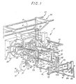
- FIGS. 1 to 7 illustrate the application of the invention to the printing of bottles of oval cross section 10.
- bottles made of synthetic material are bottles made of synthetic material.
- such a bottle 10 comprises, overall, a neck 11 and a base 12.
- the face 14 to be printed of such a bottle 10 or at least the middle portion of this face actually intended to receive an impression, will be assimilated here to a portion of cylindrical surface of radius R.
- the printing machine according to the invention comprises, of course, a frame, the production of which is within the skill of the art, and will therefore not be described in detail here.
- the printing machine comprises, for serving at least one printing station 17, detailed below, a conveyor 15, which carries at least one support object 16 specific to the support of a bottle 10 to be printed, and, in practice, from place to place, a plurality of such object-holder supports 16 each suitable for the support of such a bottle 10 to be printed.
- Such a conveyor 15 has only been partially and schematically shown in the figures.
- the conveyor 15 thus formed is in practice an endless conveyor passed in a loop on at least two return members, at least one of which is motor.
- the conveyor 15 thus passes over a return member 20 to the printing station 17, and, preferably, as shown, it is circular.
- toothed wheel rotatably mounted on the frame 13 and having from place to place, at its periphery, recesses suitable for the passage of the object-holder supports 16.
- this return member 20 On either side of this return member 20, and at a lower level, two other return members 21 are provided, for application of the conveyor 15 to the return member 20 along the upper half-circumference thereof. .
- the return members 21 are for example toothed wheels rotatably mounted on the frame 13, like the return member 20.
- any of the return members 20, 21 is motor.
- control means thus provided for the rotational drive of the engine return member of the conveyor 15 are adapted to ensure continuous rotation.
- the conveyor 15 is in continuous advance.
- each object support 16 comprises a tubular body 27, which, by lateral ears 28, is articulated, in the manner of a link, to the chains 18 constituting the conveyor 15, and which carries projecting a core 29, on which a bottle 10 to be printed can be engaged by its neck 11.
- the core 29 which it comprises is equipped with a holding member capable of ensuring, by application against the internal wall of the neck 11 of the bottle 10 to be printed engaged on it, a firm holding of such a bottle 10.
- the vials 10 to be printed extend transversely relative to the longitudinal displacement of the conveyor 15, that is to say parallel to the axes of the return members 20, 21 thereof.
- the printing machine comprises, on the one hand, a silk screen 30, forming a stencil, carried by a carriage 31, referred to below as a screen-carrying carriage, which is mounted movable longitudinally back and forth on a guide 32, and, on the other hand, a squeegee 33, carried by a carriage 34, which is also mounted movable longitudinally back and forth on a guide 35, parallel to the previous one.
- the guide 32 of the screen-carrying carriage 31 consists of two parallel bars 37, which run from one component of the frame 13 to another, parallel to the conveyor 15.
- the screen-carrying carriage 31 includes a frame 39, for supporting the screen 30, and two blocks 40, which, slidably engaged on the bars 37 constituting the associated guide 32, carry the frame 39.
- the mounting of the screen 30 on its carriage 31 can in fact be done so as to allow the screen 30 to be raised relative to the conveyor 15 if necessary, for example under the control of a cylinder.
- the guide 35 of the squeegee carriage 34 consists of three parallel bars 41, which run from one component of the frame 13 to another, parallel to the conveyor 15, and therefore parallel to the bars 37 constituting the guide 32 of the screen carriage 31.
- the squeegee 33 is mounted movable transversely with respect to the screen 30, in order to be able to be moved away from it during its return movement following printing.
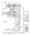
- the screen carriage 31 is controlled in synchronism with the squeegee carriage 34, from a rotary shaft 44, which, hereinafter said oscillating shaft, is coaxial with the return member 20 and which, in synchronism with the screen carriage 31 and the squeegee carriage 34 is mounted oscillating about its axis, between two bearings 45 integral with the frame 13, under the control of a rotary cam 46 locked in rotation, possibly via any suitable transmission, on the output shaft of the gear motor 25.
- a lever 48 which, by engagement means, in practice a roller 49, meshes with a track 50 of the cam 46, established on a face thereof perpendicular to its axis of rotation.
- the oscillating shaft 44 is in two parts 44A, 44B, which mesh with one another by a grooved assembly established between, on the one hand, the part 44A , and on the other hand, a sleeve 52 on which the part 44B is rotated; while the part 44A which is the one carrying the lever 48, is axially fixed, the part 44B is axially movable back and forth, the sleeve 52 on which it is wedged meshing for example for this purpose, according to methods which are well known in themselves and which are not visible in the figures, with a rotary cam locked in rotation on the output shaft of the gear motor 25, the corresponding track of this cam being for example established in this case on the edge of that -this.
- the lever 48 forms one of the sides of a deformable parallelogram whose opposite side is constituted by a lever 54, and the latter, by engagement means adjustable in position along its length, meshes with the squeegee trolley 34.
- levers 48 and 54 are connected to each other by a connecting rod 55 articulated to each of them, and the lever 54 is wedged on a shaft 56 rotatably mounted in a bearing 53 integral with the frame 13.
- the engagement means which door adjustable in position along its length, the lever 54 are constituted by a lug 57, in practice a rotary roller and the latter is freely engaged in a slide 58 which, for this purpose, carries vertically, that is to say perpendicular to its guide 35, the squeegee carriage 34.
- the slide 58 which the squeegee carriage 34 thus presents is simply formed by two rules which this squeegee carriage carries parallel to each other 34 .
- the engagement means that door thus adjustable in position along its length this lever 60 are constituted by a lug 61, and in practice a rotary roller and the latter is freely engaged in a slide 62 that the screen-carrying carriage 31 has for this purpose vertically, perpendicular to its guide 32.
- the lever 60 is removable, so that it can be removed from the oscillating shaft 44.
- the printing machine also comprises, in a manner known per se, a block 68, which, hereinafter for convenience, as a support block, is intended to successively intervene in isolation on each of the bottles 10 to be printed, and is capable, by pressing on the base 12 of such a bottle 10 to be printed, of controlling the angular orientation thereof around a transverse axis relative to the guides 32, 35 of the screen-carrying carriages 31 and squeegee holder 34, this transverse axis being that along which extend these vials 10 to be printed when they are carried, as described above, by the object-holding supports 16 on the core 29 of which they are engaged, and therefore being, in practice, the very axis of said vials 10 to be printed in the embodiment shown.
- a block 68 which, hereinafter for convenience, as a support block, is intended to successively intervene in isolation on each of the bottles 10 to be printed, and is capable, by pressing on the base 12 of such a bottle 10 to be printed, of controlling the angular
- such a support block 68 is conformed to the specific configuration of the base 12 of the vials 10 to be printed, so as to be able to engage at least partially on such a base 12, its corresponding leading edge preferably being chamfered to facilitate such engagement.
- This support 69 is itself carried by a lever 71, and the latter is set in rotation on the oscillating shaft 44, and, more precisely, on the axially movable reciprocating part 44B thereof.
- the support 69 and the lever 71 are split: the support 69 is formed of two blocks 69A, 69B and the lever 71 of two arms 71 A, 71 B; the arm 71A, which carries the block 69A, is axially fixed, being suitably rotatably mounted on the frame 13, by the bearing 45 of the oscillating shaft 44, while the arm 71B, which carries the block 69B, is wedged in rotation, while being adjustable in position; on the part 44B of the oscillating shaft 44, and is therefore, like this one, axially movable back and forth.
- the shaft 70 carrying the support block 68 is axially wedged on the block 69B, and it is therefore wedged in rotation and wedged axially on the axially movable part 44B of the oscillating shaft 44, while, by a spline mounting , it slides axially sliding block 69A, while being locked in rotation thereon; in practice, this shaft 70 is also in two parts 70A, 70B, connected to each other by an elastic coupling 92.
- the arm 71 B is doubled by an arm 90, which, parallel to the oscillating shaft 44, carries a finger 91, and which, by this finger 91, is engaged with the arm 71 A.
- the support block 68 is locked in rotation on a lever 72 which, by engagement means adjustable in position along its length, meshes with a carriage 73, hereinafter said for convenience, control carriage, movably mounted on a guide 74 in synchronism with the squeegee carriage 34.
- this control carriage 73 comprises two bars 76, which extend parallel to those 37, 41 constituting the guides 32, 35 of the screen-carrying carriage 31 and the squeegee carriage 34, and the guide 74 corresponding consists of two brackets 77, which, established parallel to each other, at a distance from each other, are integral with the frame 13, and are slidably traversed by said bars 76.
- the lever 72 for controlling the support block 68 is locked in rotation on the shaft 70 carrying the latter, and the engagement means that door adjustable in position this lever 72 consist of a lug 79, in practice a rotary roller, freely engaged in a slide 80 carried for this purpose vertically, that is to say perpendicular to its bars 76, by the control carriage 73 concerned.
- the rotary roller constituting the lug 79 is carried by a pin 81, which passes through a buttonhole 82 provided for this purpose longitudinally in the lever 72, with locking in position at any point thereof. ci by a nut 125, which, disposed on a first side of this lever 72, cooperates, in maintenance, with a head 83 established on the other side thereof.
- the corresponding slide 80 of the control carriage 73 is formed between two rails 123 mounted vertically on a support block 124 secured to the bars 76 that this control carriage 73 comprises.
- the squeegee carriage 34 and the control carriage 73 of the support block 68 each have, in parallel with one another, a slide.
- the slide 58 For the squeegee carriage 34, it is the slide 58, extended sufficiently downward for this purpose; for the control carriage 73 of the support block 68, it is a slide 85, which for this purpose has this control carriage 73 vertically, parallel to its slide 80.
- cranks 88, 89 For their engagement with their respective carriages, these cranks 88, 89 carry, as previously, a lug 93, 99, preferably consisting of a rotary roller.
- R ′ The radius of the return member 20 from the conveyor 15 to the printing station 17, or radius of gyration of the circular path followed by the vials 10 to be printed when they are scrolled at the printing station, will be denoted by R ′ below. 17.
- the radius of curvature R of the printing face 14 of the vials 10 concerned is equal to the radius of gyration R 'increased by the half thickness e / 2 of these bottles, e being their thickness.
- the roller 57 constituting the engagement means adjustable in position carried by the lever 54 is disposed in line with the articulation 56 of this lever 54 on the frame 13.
- the squeegee carriage 34 is therefore immobilized, and therefore also the control carriage 73.
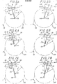
- the bottle 10 concerned then comes, by a generator of its face 14 to be printed, in contact with the screen 30, FIG. 5A.
- the face 14 to be printed generally belonging to a cylindrical surface of radius R centered on the oscillating shaft 44 around which the gyration of the bottle 10 concerned takes place, the latter then develops without sliding on contact of the screen 39, FIG. 5B, while the squeegee 33 remains stationary at the right of its generator of contact with this screen 39, in the vertical plane, which, as shown diagrammatically in broken lines by its trace in the figures, passes through the axis of the return member 20.
- the support block 68 applied to its base 12 firmly controls the orienta angular around its axis, which, as mentioned above, extends transversely with respect to the guides of the screen-carrier carriage 32 and of the squeegee-carriage 34, said axis being in practice that of said support block 68.
- Such an adjustment can, for example, be made using an abacus suitably established for this purpose as a function of the possible radii of curvature.
- the roller 79 is both close to the periphery of the return member 20 and to the vertical plane V passing through the axis of the latter, so that it is therefore located away from the plane passing through the axis of the support block 68, and the axis of the return member 20, and, jointly, the roller 57 is moved accordingly, above the shaft 56, for appropriate movement of the squeegee 33.
- the squeegee carriage 34 then being movable in the same direction as the screen carrier 31, as indicated above, the way 10 to be printed then develops still properly in contact with the screen 30, as illustrated in FIGS. 6A, 6B, the roller 79 which in practice materializes the center of curvature of the face 14 to be printed moving parallel to the screen 30, in the same direction as the latter, but with a less stroke, and in synchronism with squeegee 33.
- the bottle 10 during printing is jointly subjected to a slight rotational movement on itself, 'around its axis, under the control of the block d 'support 68, which controls the angular orientation around said axis at all times.
- the squeegee carriage 34 and the screen carriage 31 then move in opposite directions relative to each other.
- the support block 68 departs from the base 12 of such a bottle 10.
- the oscillating shaft 44 then returns the support block 68 to its initial position, while jointly the screen 30 and the squeegee 33 also return to their initial position.
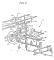
- FIG. 8 illustrates the application of the printing machine according to the invention to the printing of bottles 10 of circular cross section.
- the support block 68 is rotatably mounted in a support 69 which is itself carried by a lever 71 directly mounted oscillating on the frame 13, this lever 71 being locked in rotation on a shaft 44 mounted oscillating around its axis on said frame 13.
- lever 72 on which the support block 68 is rotated is eliminated, this lever 72 being advantageously made for this removable purpose, according to the methods described above for the lever 60, and it is substituted therefor, according to methods, which, not forming part of the present invention, will not be described in detail here, a pinion 95.
- This pinion 95 then meshes with a rack 96, which is fixed, being carried by the frame 13, and which is curved, being centered on the axis of the oscillating shaft 44.
- the lever 60 intended for controlling the screen-carrying carriage 31 is locked in rotation on an auxiliary shaft 97, which is rotatably mounted in a bearing 98 integral with the frame 13, and on which a lever 99 'is locked in rotation.
- this lever 99 By engagement means constituted in practice by a lug 101, and more precisely by a rotary roller, this lever 99 'meshes with a slide 100 provided for this purpose vertically on an auxiliary carriage 102, mounted movably on a guide parallel to the carriage squeegee holder 34, and in synchronism therewith.
- this auxiliary carriage 102 is mounted movably on the bars 41 forming the guide 35 of the squeegee carriage 34.
- the lever 48 also assumed to be sufficiently extended upward for this purpose, meshes with the slide 100 of the auxiliary carriage 102, for controlling the latter.
- the screen-carrying carriage 31 is in this case movable back and forth in the opposite direction relative to the squeegee carriage 34, while being controlled by synchronism with it.
- the support block 68 ensures at least partial rotation of the objects 10 to be printed on themselves during their printing, this block 68 being provided with this effect of a retractable lug which engages with a corresponding notch also provided for this purpose on the base 12 of such a bottle, according to methods well known in themselves.
- the frame 39 of the screen 30 is mounted vertically movable on the carriage 31 which carries it, against springs 105, and it carries by gravity on a roller 106 disposed at the end of a lever 107 itself. - even locked in rotation on the oscillating shaft 44.
- the screen and the squeegee should normally be preferably adjustable in height on the carriages which carry them.
- printing stations can be provided, with, if desired, between them, other processing stations such as drying and / or steaming station.
Landscapes
- Engineering & Computer Science (AREA)
- Mechanical Engineering (AREA)
- Screen Printers (AREA)
Claims (9)
Applications Claiming Priority (2)
| Application Number | Priority Date | Filing Date | Title |
|---|---|---|---|
| FR8209550A FR2527986A1 (fr) | 1982-06-02 | 1982-06-02 | Machine a imprimer a l'ecran de soie |
| FR8209550 | 1982-06-02 |
Publications (2)
| Publication Number | Publication Date |
|---|---|
| EP0095987A1 EP0095987A1 (de) | 1983-12-07 |
| EP0095987B1 true EP0095987B1 (de) | 1985-09-18 |
Family
ID=9274542
Family Applications (1)
| Application Number | Title | Priority Date | Filing Date |
|---|---|---|---|
| EP19830401118 Expired EP0095987B1 (de) | 1982-06-02 | 1983-06-02 | Siebdruckmaschine |
Country Status (3)
| Country | Link |
|---|---|
| EP (1) | EP0095987B1 (de) |
| DE (1) | DE3360836D1 (de) |
| FR (1) | FR2527986A1 (de) |
Families Citing this family (3)
| Publication number | Priority date | Publication date | Assignee | Title |
|---|---|---|---|---|
| DE3637638A1 (de) * | 1986-11-05 | 1988-05-11 | Kammann Maschf Werner | Vorrichtung zum dekorieren von objekten |
| DE3740457A1 (de) * | 1987-11-28 | 1989-06-08 | Balsfulland Gmbh Maschf Geb | Siebdruckmaschine |
| EP0535259A1 (de) * | 1991-09-27 | 1993-04-07 | Trong Chia Chiang | Vorrichtung für Wölbungsfeinanpassung bei Wölbungs-Siebdruckmaschinen und Bügelpressen |
Family Cites Families (1)
| Publication number | Priority date | Publication date | Assignee | Title |
|---|---|---|---|---|
| US4122768A (en) * | 1977-04-19 | 1978-10-31 | Dubuit Of America, Inc. | Screen printing press attachment for printing objects of revolution |
-
1982
- 1982-06-02 FR FR8209550A patent/FR2527986A1/fr active Granted
-
1983
- 1983-06-02 DE DE8383401118T patent/DE3360836D1/de not_active Expired
- 1983-06-02 EP EP19830401118 patent/EP0095987B1/de not_active Expired
Also Published As
| Publication number | Publication date |
|---|---|
| FR2527986B1 (de) | 1985-03-22 |
| DE3360836D1 (en) | 1985-10-24 |
| FR2527986A1 (fr) | 1983-12-09 |
| EP0095987A1 (de) | 1983-12-07 |
Similar Documents
| Publication | Publication Date | Title |
|---|---|---|
| EP1723060B1 (de) | Fördereinrichtung mit einem verbesserten übergabearm | |
| FR2465665A1 (fr) | Dispositif de repartition de recipients en plusieurs files et machine utilisant un tel dispositif | |
| CA1288678C (fr) | Machine d'encaissage pour caisses americaines | |
| FR2745555A1 (fr) | Machine pour decorer des objets un par un | |
| EP0095987B1 (de) | Siebdruckmaschine | |
| FR2543470A1 (fr) | Installation de transfert a mecanisme asservi de commande de la rotation des pinces de transfert | |
| EP0443395B1 (de) | Vorrichtung zum Eindrücken und Schneiden in Längsrichtung eines laufenden Materialbandes | |
| FR2487735A1 (fr) | Machine a imprimer a commande mecanique centralisee | |
| FR2463003A1 (fr) | Perfectionnements aux machines de serigraphie concernant la monture porte-objets et son mouvement relatif par rapport a l'ecran | |
| MC687A1 (fr) | Machine à décorer en plusieurs couleurs | |
| EP1495844A1 (de) | Nockenbetätigter mechanischer Manipulator für Linear- und Drehbewegung und Fertigungsmaschine mit solchen Manipulatoren | |
| FR2906179A1 (fr) | Dispositif de transfert et machine d'impression. | |
| EP0260178B1 (de) | Druckmaschine für den Druck auf eine konvexe Oberfläche | |
| FR2905622A1 (fr) | Manipulateur mecanique a mouvement en u et machine d'assemblage equipee de tels manipulateurs. | |
| CH392385A (fr) | Dispositif transporteur pour machine à fa^conner des pièces de métal | |
| FR2507128A1 (fr) | Procede et dispositif pour decorer la surface cylindrique ou conique d'une piece d'oeuvre | |
| EP0059674A1 (de) | Siebdruckvorrichtung für Flakons oder dgl. | |
| FR2679170A1 (fr) | Tete d'impression pour machine a imprimer comportant un barillet rotatif pour l'impression d'objets. | |
| EP0429317B1 (de) | Druckmaschine mit gesteuerter Hebevorrichtung für die Druckeinheit | |
| EP0565615B1 (de) | Beschichtungsmaschine, insbesondere zur beschichtung des inneres eines körpers mit viereckigem querschnitt und grossen abmessungen wie eines schiffscontainers | |
| EP1867480B1 (de) | Druckgerät | |
| BE506984A (de) | ||
| FR2806066A1 (fr) | Dispositif d'alimentation pour alimenter en objets des porte-objets, en particulier pour machine a imprimer, et machine a imprimer equipee d'un tel dispositif | |
| FR2527985A1 (fr) | Machine a imprimer en continu des objets necessitant une rotation au moins partielle sur eux-memes au cours de leur impression | |
| CH254253A (fr) | Machine rotative à imprimer en taille-douce. |
Legal Events
| Date | Code | Title | Description |
|---|---|---|---|
| PUAI | Public reference made under article 153(3) epc to a published international application that has entered the european phase |
Free format text: ORIGINAL CODE: 0009012 |
|
| AK | Designated contracting states |
Designated state(s): DE FR GB IT NL |
|
| 17P | Request for examination filed |
Effective date: 19840213 |
|
| ITF | It: translation for a ep patent filed | ||
| GRAA | (expected) grant |
Free format text: ORIGINAL CODE: 0009210 |
|
| AK | Designated contracting states |
Designated state(s): DE FR GB IT NL |
|
| REF | Corresponds to: |
Ref document number: 3360836 Country of ref document: DE Date of ref document: 19851024 |
|
| PLBE | No opposition filed within time limit |
Free format text: ORIGINAL CODE: 0009261 |
|
| STAA | Information on the status of an ep patent application or granted ep patent |
Free format text: STATUS: NO OPPOSITION FILED WITHIN TIME LIMIT |
|
| 26N | No opposition filed | ||
| PGFP | Annual fee paid to national office [announced via postgrant information from national office to epo] |
Ref country code: NL Payment date: 19870630 Year of fee payment: 5 |
|
| PG25 | Lapsed in a contracting state [announced via postgrant information from national office to epo] |
Ref country code: NL Effective date: 19890101 |
|
| NLV4 | Nl: lapsed or anulled due to non-payment of the annual fee | ||
| PGFP | Annual fee paid to national office [announced via postgrant information from national office to epo] |
Ref country code: DE Payment date: 19930621 Year of fee payment: 11 |
|
| ITTA | It: last paid annual fee | ||
| PG25 | Lapsed in a contracting state [announced via postgrant information from national office to epo] |
Ref country code: DE Effective date: 19950301 |
|
| PGFP | Annual fee paid to national office [announced via postgrant information from national office to epo] |
Ref country code: FR Payment date: 20010411 Year of fee payment: 19 |
|
| PGFP | Annual fee paid to national office [announced via postgrant information from national office to epo] |
Ref country code: GB Payment date: 20010525 Year of fee payment: 19 |
|
| REG | Reference to a national code |
Ref country code: GB Ref legal event code: IF02 |
|
| PG25 | Lapsed in a contracting state [announced via postgrant information from national office to epo] |
Ref country code: GB Free format text: LAPSE BECAUSE OF NON-PAYMENT OF DUE FEES Effective date: 20020602 |
|
| GBPC | Gb: european patent ceased through non-payment of renewal fee |
Effective date: 20020602 |
|
| PG25 | Lapsed in a contracting state [announced via postgrant information from national office to epo] |
Ref country code: FR Free format text: LAPSE BECAUSE OF NON-PAYMENT OF DUE FEES Effective date: 20030228 |
|
| REG | Reference to a national code |
Ref country code: FR Ref legal event code: ST |