EP0095958B1 - Moteur électrique à stator bobiné, et son procédé de fabrication - Google Patents
Moteur électrique à stator bobiné, et son procédé de fabrication Download PDFInfo
- Publication number
- EP0095958B1 EP0095958B1 EP83400985A EP83400985A EP0095958B1 EP 0095958 B1 EP0095958 B1 EP 0095958B1 EP 83400985 A EP83400985 A EP 83400985A EP 83400985 A EP83400985 A EP 83400985A EP 0095958 B1 EP0095958 B1 EP 0095958B1
- Authority
- EP
- European Patent Office
- Prior art keywords
- plate
- wires
- terminal
- stator
- motor according
- Prior art date
- Legal status (The legal status is an assumption and is not a legal conclusion. Google has not performed a legal analysis and makes no representation as to the accuracy of the status listed.)
- Expired
Links
Images
Classifications
-
- H—ELECTRICITY
- H02—GENERATION; CONVERSION OR DISTRIBUTION OF ELECTRIC POWER
- H02K—DYNAMO-ELECTRIC MACHINES
- H02K3/00—Details of windings
- H02K3/46—Fastening of windings on the stator or rotor structure
- H02K3/50—Fastening of winding heads, equalising connectors, or connections thereto
-
- H—ELECTRICITY
- H02—GENERATION; CONVERSION OR DISTRIBUTION OF ELECTRIC POWER
- H02K—DYNAMO-ELECTRIC MACHINES
- H02K5/00—Casings; Enclosures; Supports
- H02K5/04—Casings or enclosures characterised by the shape, form or construction thereof
- H02K5/12—Casings or enclosures characterised by the shape, form or construction thereof specially adapted for operating in liquid or gas
- H02K5/128—Casings or enclosures characterised by the shape, form or construction thereof specially adapted for operating in liquid or gas using air-gap sleeves or air-gap discs
-
- H—ELECTRICITY
- H02—GENERATION; CONVERSION OR DISTRIBUTION OF ELECTRIC POWER
- H02K—DYNAMO-ELECTRIC MACHINES
- H02K5/00—Casings; Enclosures; Supports
- H02K5/04—Casings or enclosures characterised by the shape, form or construction thereof
- H02K5/22—Auxiliary parts of casings not covered by groups H02K5/06-H02K5/20, e.g. shaped to form connection boxes or terminal boxes
- H02K5/225—Terminal boxes or connection arrangements
-
- H—ELECTRICITY
- H02—GENERATION; CONVERSION OR DISTRIBUTION OF ELECTRIC POWER
- H02K—DYNAMO-ELECTRIC MACHINES
- H02K2203/00—Specific aspects not provided for in the other groups of this subclass relating to the windings
- H02K2203/03—Machines characterised by the wiring boards, i.e. printed circuit boards or similar structures for connecting the winding terminations
-
- H—ELECTRICITY
- H02—GENERATION; CONVERSION OR DISTRIBUTION OF ELECTRIC POWER
- H02K—DYNAMO-ELECTRIC MACHINES
- H02K2203/00—Specific aspects not provided for in the other groups of this subclass relating to the windings
- H02K2203/06—Machines characterised by the wiring leads, i.e. conducting wires for connecting the winding terminations
-
- H—ELECTRICITY
- H02—GENERATION; CONVERSION OR DISTRIBUTION OF ELECTRIC POWER
- H02K—DYNAMO-ELECTRIC MACHINES
- H02K2211/00—Specific aspects not provided for in the other groups of this subclass relating to measuring or protective devices or electric components
- H02K2211/03—Machines characterised by circuit boards, e.g. pcb
Definitions
- the present invention relates to an electric motor and its manufacturing process.
- the motors of the field of the invention include a wound stator, the output wires of which must be connected to a winding selection and supply member, for example to vary the speed, the torque or the direction of rotation of the motor. at the discretion of its user.
- Electric motors are mass-produced devices. It is therefore particularly important for the manufacturing price to be reduced, that they are of a simple constitution in particular that the number of parts constituting them is reduced to a minimum.
- the engine according to the invention satisfies these conditions to a greater extent than the engines known up to now.
- the motor according to the invention is characterized in that the wires are stretched on one face of a plate, the plate carrying out a maintenance and / or a forming of the output bun of the coil wires.
- a plate contributes to the reduction in the number of engine components which results, in addition to the reduction in the manufacturing price, better reliability.
- the prior art also has the drawback that it is necessary to solder or weld the ends of the stator wires to a printed circuit or to terminals.
- the invention makes it possible to efficiently use another electrical connection technology.
- the plate has the shape of a disc at the end of a cylindrical sleeve forced into the stator opening.
- the plate is for example made of an insulating material obtained by molding.
- the plate is used to guide the wires leaving the stator and a terminal block is fixed to this plate. The ends of the wires guided on the plate are held on the terminal block.
- This terminal block is, in an exemplary embodiment, the female part of a connector in which a printed circuit can be inserted.
- the output wires of the stator coils are gathered on a carrier plate.
- the plate is arranged in a plane perpendicular to the axis of the motor. It is fixed to the motor on the side where the wires to be connected come out of the bun.
- the plate also carries on its periphery a connector which makes it possible to connect each coil wire to a track of a printed circuit board.
- the plate is removable and can be plugged into the connector at will. It supplies the motor with electrical power and changes its electromechanical characteristics.
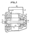
- an electric motor according to the invention is shown.
- Such an engine comprises a rotor 1 secured to a shaft 5 mounted inside a cylindrical stator bore.
- a winding 3,4 is installed in the stator notches. These notches make it possible to maintain and isolate each of the coils which make up the stator winding 3,4.
- the winding On either side (of the carcass 2) of the stator, the winding has two puffed shapes, constituted by the entanglement of the heads or ends of the coils. When the winding is large, it is necessary that these ends of the winding are maintained. For this, presses are produced in buns 3 and 4.
- "upper" bun is called the bun from which the ends of the wires come out of each of the coils.
- Each coil has the shape of a flat solenoid composed of a large number of turns. Each coil therefore has one end of the input wire and one end of the output wire.
- the bun 4 has approximately the shape of a spherical dome.
- This bun will be left raw insertion.
- a formation of the single upper bun 3 is sufficient to maintain tension on the wires of the bun 4 and to ensure adequate mechanical strength.
- the upper bun is formed by forcing a matrix 100 into the stator bore.
- This matrix mainly comprises a plate or cup 9 connected to a cylindrical body 8 which penetrates inside the stator bore .
- the cylindrical body 8 penetrates inside the stator notches so as to clear the stator-rotor air gap.
- the body 8 can serve as a notch bottom flap to hold each coil in the notches.
- the body 8 serves as a means of permanent attachment to the plate 9 on the stator on the side of the upper bun 3 which it allows to form.
- the matrix 100 ends in a cylinder 80 with a diameter smaller than that of the body 8, which penetrates inside the bun 4 so as to provide it with an opening through which the motor shaft 5 can pass.
- the bearing 7 is forcibly mounted in the narrowed part 80 of the body 8 at the opening in the lower bun 4.
- sealing means 13, 14 are arranged at the rear of the engine, that is to say of the side of the lower bun 4, on its carcass exterior 11 so as to ensure good sealing of the engine block.
- These means may include a tight seal 13 of toroidal shape and a screw 14 fixed to the carcass 11.
- the drive shaft 5 is on the other side carried by a bearing 6 fixed to a carrier seal 16. The tightness to the front of the motor is completed by a seal 15.
- the plate 9 of the forming die is linked to a terminal block 10.
- the terminal block 10 is carried by the periphery of the plate 9. It is folded down along the carcass 11 of the motor .
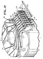
- the various free wires of the stator coils which exit from the side of the upper bun 3 are fixed to the cup and transmitted to the terminal block 10 as shown in FIG. 2.
- FIG. 2 a wound stator mounted according to the invention.
- the stator winding On the carcass 2 has been mounted the stator winding, the upper bun of which can be seen 3.
- the forming matrix 100 is visible through the upper part of the plate 9.
- Eight stator wires are visible corresponding to the input and output ends of four coils inserted in the notches of the stator 2.
- the ends of these wires are mounted in the terminal block 10.
- the wires 20-27 are fixed by fixing means 28-30 so as to be rigidly held in place whatever the mechanical manipulations on engine.
- the terminal block 10 is connected to the plate 9 proper by an elbow support 31 which makes it possible to bring the connection direction 81 parallel to the axis of the motor.
- the ends 20-27 of the stator wires are maintained by two series of hot crimping.
- These hot crimps deform the edges of the channels traced on the terminal block 10 and its support 31. They are produced by a pressure exerted by a heating electrode 34 directed successively according to the arrows 35 and 36.
- the wires 20-27 are thus kept at the inside the canals.
- the means for fixing the wires 20-27 to the plate 9 comprise bars 28-30 pierced with cylindrical holes which allow the passage and fixing of the wires stretched over the cup.
- Each wire comes from the bun and is securely held in its channel by a slight tension at the end of the wires during the hot crimping operation described. The distances between the wires are such that no crossing takes place. In this way, the conventional operation of dissolving the stator wires at their exit from the bun 3 is avoided, which the techniques of the prior art require to be carried out.
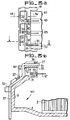
- FIG. 3b there is shown a section along several axes of a matrix according to the invention.
- the cylindrical body 8 has been cut along a plane diametrical to the shaft 5. Then the cut passes along a wire 27 at the end of the terminal block 10. The wire 27 passes to the inside a hole drilled in the retaining strip 32. 11 undergoes a first input bend on the support 31 and a second bend at the input of the terminal block 10. Finally, at the top of the terminal block 10, the wire is again bent.
- the crimps described allow it to be kept inside the channels drilled on the terminal block 10 and on the cup 9.
- a connector particularly suitable for the invention comprises a first housing, which here consists of the terminal block 10, in which is fixed all of the stator wires to be connected to a printed circuit 47.
- the connector comprises a second housing 51 inside the terminal block 10. Terminal block 10 and housing 51 are secured by latching means not shown.
- the second housing 51 carries a plurality of conductive lugs such as the metallic conductive lug 39 of a particular shape.
- This terminal has two parts 40 and 41.
- the first part 40 has a particular shape which makes it suitable for making a connection by removing insulation.
- the second part 41 includes a connection part to a printed circuit, at one of these tracks 48-50, by plugging in the printed circuit 47.
- the terminal is rigidly held inside the housing 51 by means not shown. which make it possible to prevent, once the first part 40 connected to the wire 27, from exerting any constraint whatsoever on the insulated wire. Indeed, if this precaution is not taken, efforts can be exerted on the connected wire when one introduces or when one pulls out the printed circuit 47 of the second part 41 of the terminal 39. As the wires of stator coils are fragile, this precaution is necessary.
- the terminal 39 is of the type known as hot crimping.
- the terminal 39 visible in view from below in FIG. 3a, comprises a first part 40 of enveloping shape which makes it possible to surround the wire 27 to be connected. As the wire 27 is insulated, it is necessary to remove the insulation. For this, as shown at the top of FIG. 3a, two hot crimping electrodes are approached on either side of the terminal to be crimped according to arrows 45 and 46. Pressure is exerted on the heating electrodes . The insulation evaporates on heat and the terminal is crimped to the wire ensuring permanent contact.
- the rigid connection of the terminal is ensured by a firstly by a rigid connection (not shown) of the terminal to the housing and secondly by a non-removable and rigid snap-fastening of the housing 51 to the terminal block 10.
- the lugs are installed in the housing 51.
- the rear part of the enveloping shape of their first connection part to the insulated wire is, at the insertion of the housing 51 in the terminal block 10, parallel to the direction 81 of connection shown in Figure 2.
- terminal block 10 and housing 51 are rigidly fixed to each other.
- a first bending tool makes it possible to fold each of the rear parts and then hot crimping, lug by lug, is carried out.
- each part of hot connection to the wire comprises a boss 42-44 which opposes the effect of chasing the wire when the pressure of the crimping electrodes is exerted.
- the part 41 for connection of the terminal to the printed circuit 47 can be of the lyre type as shown in FIG. 3b.
- the part 41 is of the lamella type.
- the terminal of a width substantially equal to that of each track 48-50 of FIG. 3a, is bent in the vertical plane of FIG. 3b, so as to form a spring leaf, conductive.
- the circuit board 47 enters the housing 51 between the top of the housing and the leaf spring.
- the first part of the terminal is of the type with mechanical removal of insulation.
- the terminal carries on the side of the wire, a cutting slot intended to pierce the insulation and to establish contact with the conductive core of the insulated wire.
- the stator coils are installed in notches of the stator 2 by the stator bore 33. Then the leads of the coils 20-27 are released.
- the forming die 100 is introduced from the top of the upper bun 3. By pressing, the formation of the upper bun 3 and the opening of the lower bun 4 are simultaneously obtained.
- the wires are then installed in the fixing means on the cup and then placed in the channels on the terminal block 10. Finally, a new tension is exerted on the wires 20 to 27 at their free ends.
- the wires are again slightly stretched and a hot crushing of the channels such as the constriction 38 is again carried out according to arrow 35 by the hot crimping bar 34. At the end of this operation, the winding impregnation operation.
- each insulated wire 20-27 to an adapter printed circuit.
- a printed circuit makes it possible to produce a configuration of the winding which corresponds to the desired operation of the electric motor.
- the wires 20-27 have been fixed to the cup 9 in the most convenient way from the point of view of the insulation at the outlet of the bun.
- the printed circuit makes it possible to connect coils to each other and to special components such as an inverter, a capacitor, a selector.
- the card is also connected to the motor power supply.
Landscapes
- Engineering & Computer Science (AREA)
- Power Engineering (AREA)
- Manufacture Of Motors, Generators (AREA)
- Insulation, Fastening Of Motor, Generator Windings (AREA)
Applications Claiming Priority (2)
| Application Number | Priority Date | Filing Date | Title |
|---|---|---|---|
| FR8209256A FR2527857A1 (fr) | 1982-05-27 | 1982-05-27 | Moteur electrique a stator bobine et son procede de fabrication |
| FR8209256 | 1982-05-27 |
Publications (2)
| Publication Number | Publication Date |
|---|---|
| EP0095958A1 EP0095958A1 (fr) | 1983-12-07 |
| EP0095958B1 true EP0095958B1 (fr) | 1986-09-24 |
Family
ID=9274398
Family Applications (1)
| Application Number | Title | Priority Date | Filing Date |
|---|---|---|---|
| EP83400985A Expired EP0095958B1 (fr) | 1982-05-27 | 1983-05-17 | Moteur électrique à stator bobiné, et son procédé de fabrication |
Country Status (3)
| Country | Link |
|---|---|
| EP (1) | EP0095958B1 (enExample) |
| DE (1) | DE3366410D1 (enExample) |
| FR (1) | FR2527857A1 (enExample) |
Families Citing this family (8)
| Publication number | Priority date | Publication date | Assignee | Title |
|---|---|---|---|---|
| DE3534883C2 (de) * | 1985-09-30 | 1994-01-13 | Siemens Ag | Am Ständerblechpaket eines elektrischen Kleinmotors festlegbare Kunststoff-Verbindungsvorrichtung |
| DE3625109A1 (de) * | 1986-07-24 | 1988-02-04 | Hanning Elektro Werke | Stator fuer induktionsmotoren |
| DE8633206U1 (de) * | 1986-12-11 | 1987-02-26 | Licentia Patent-Verwaltungs-Gmbh, 6000 Frankfurt | Elektromotor zum Antrieb einer Flüssigkeitspumpe |
| DE3731187A1 (de) * | 1987-09-17 | 1989-03-30 | Oplaender Wilo Werk Gmbh | Elektromotor |
| DE3843477A1 (de) * | 1988-12-23 | 1990-06-28 | Oplaender Wilo Werk Gmbh | Spaltrohr-elektromotor |
| DE4302449A1 (de) * | 1993-01-29 | 1994-08-04 | Miele & Cie | Staubsauger mit einem Gebläseaggregat |
| FR2711457B1 (fr) * | 1993-10-19 | 1995-11-24 | Valeo Systemes Dessuyage | Stator de machine électrique et machine électrique comme un moteur à commutation électronique équipée d'un tel stator. |
| GB2445775A (en) * | 2007-01-17 | 2008-07-23 | Johnson Electric Sa | Electric motor having releasable connection for pcba |
Family Cites Families (8)
| Publication number | Priority date | Publication date | Assignee | Title |
|---|---|---|---|---|
| US3448431A (en) * | 1966-03-17 | 1969-06-03 | Elco Corp | Contact carrier strip |
| JPS4954801A (enExample) * | 1972-09-27 | 1974-05-28 | ||
| US3984712A (en) * | 1974-11-11 | 1976-10-05 | Industra Products, Inc. | End turn shield and winding connector |
| US4215464A (en) * | 1977-10-25 | 1980-08-05 | General Electric Company | Method of making a stator connection assembly |
| US4133598A (en) * | 1977-11-14 | 1979-01-09 | Allen-Bradley Company | Terminal block |
| DE2842119C2 (de) * | 1978-09-27 | 1984-09-20 | Siemens Ag, 1000 Berlin Und 8000 Muenchen | Außenläufermotor |
| DE2912802C2 (de) * | 1979-03-30 | 1983-11-10 | Siemens AG, 1000 Berlin und 8000 München | Anordnung zum Verschalten der Wicklungsenden der Statorwicklung mit einem äußeren Anschlußkabel in einem Außenläufermotor |
| DE2913937C2 (de) * | 1979-04-06 | 1986-08-21 | Frankl & Kirchner GmbH & Co KG Fabrik für Elektromotoren u. elektrische Apparate, 6830 Schwetzingen | Leiterplatte mit Steckverbinder |
-
1982
- 1982-05-27 FR FR8209256A patent/FR2527857A1/fr active Granted
-
1983
- 1983-05-17 DE DE8383400985T patent/DE3366410D1/de not_active Expired
- 1983-05-17 EP EP83400985A patent/EP0095958B1/fr not_active Expired
Also Published As
| Publication number | Publication date |
|---|---|
| FR2527857A1 (fr) | 1983-12-02 |
| DE3366410D1 (en) | 1986-10-30 |
| EP0095958A1 (fr) | 1983-12-07 |
| FR2527857B1 (enExample) | 1984-12-14 |
Similar Documents
| Publication | Publication Date | Title |
|---|---|---|
| EP0766882B1 (fr) | Section de conducteur pour une armature de stator d'une machine dynamoelectrique polyphasee | |
| EP0735629B1 (fr) | Agencement de connexion pour fils conducteurs électriques et module, notamment de type bloc de jonction, équipé d'un tel agencement | |
| EP0095958B1 (fr) | Moteur électrique à stator bobiné, et son procédé de fabrication | |
| US3751801A (en) | Method and apparatus for terminating electrical ribbon cable | |
| JPS6233730B2 (enExample) | ||
| EP3682531B1 (fr) | Système de connexion pour machine électrique | |
| EP0247360B1 (fr) | Agencement de connexion à fente pour fil électrique et embout d'outil de connexion correspondant | |
| JP2744532B2 (ja) | 電動機の電機子および該電機子の巻き付け並びに製造方法 | |
| FR2466894A1 (fr) | Bobine de moteur electrique | |
| FR2719166A1 (fr) | Adaptateur pour un connecteur multibroche & connecteur multibroche correspondant. | |
| EP0208233A1 (fr) | Agencement de connexion auto-dénudant encastré pour appareillage électrique et outil de connexion pour un tel agencement | |
| US6189769B1 (en) | Method of cable wire arrangement | |
| EP0117166B1 (fr) | Embout en bande pour conducteur électrique, son procédé de fabrication et son application à la fabrication des fils conducteurs munis d'un embout ou d'une cosse | |
| JP3916990B2 (ja) | リード線結線構造 | |
| US5760505A (en) | Apparatus and method for introducing wire slack in stator windings | |
| JP4522402B2 (ja) | リード線結線構造及びその形成方法 | |
| JP3369815B2 (ja) | 電動機の引き出し線の接続部絶縁紙とリード線接続部の絶縁処理方法 | |
| WO1986003063A1 (fr) | Dispositif de connexion | |
| EP1085553A1 (fr) | Procédé de fabrication en série de modules porte-fusible et modules porte-fusible obtenus par le procédé | |
| EP0662737B1 (fr) | Agencement de connexion à fente pour fil électrique raccordé à une pièce montée dans un boítier | |
| FR2890780A1 (fr) | Contacteur de demarreur de moteur thermique comportant des moyens perfectionnes de raccordement electrique de son bobinage | |
| FR2846806A1 (fr) | Procede de fabrication de conducteurs electriques en forme d'epingles en u, dispositif pour la mise en oeuvre de ce procede et conducteurs ainsi obtenus | |
| JPH0460308B2 (enExample) | ||
| FR2527847A1 (fr) | Connecteur electrique pour fils conducteurs isoles | |
| FR3149151A1 (fr) | Bobine et stator pour machine électrique, machine électrique et procédé d’assemblage associé |
Legal Events
| Date | Code | Title | Description |
|---|---|---|---|
| PUAI | Public reference made under article 153(3) epc to a published international application that has entered the european phase |
Free format text: ORIGINAL CODE: 0009012 |
|
| AK | Designated contracting states |
Designated state(s): BE CH DE GB IT LI NL |
|
| 17P | Request for examination filed |
Effective date: 19831227 |
|
| RAP1 | Party data changed (applicant data changed or rights of an application transferred) |
Owner name: POMPES SALMSON |
|
| GRAA | (expected) grant |
Free format text: ORIGINAL CODE: 0009210 |
|
| AK | Designated contracting states |
Kind code of ref document: B1 Designated state(s): BE CH DE GB IT LI NL |
|
| REF | Corresponds to: |
Ref document number: 3366410 Country of ref document: DE Date of ref document: 19861030 |
|
| ITF | It: translation for a ep patent filed | ||
| PLBE | No opposition filed within time limit |
Free format text: ORIGINAL CODE: 0009261 |
|
| STAA | Information on the status of an ep patent application or granted ep patent |
Free format text: STATUS: NO OPPOSITION FILED WITHIN TIME LIMIT |
|
| 26N | No opposition filed | ||
| ITTA | It: last paid annual fee | ||
| PGFP | Annual fee paid to national office [announced via postgrant information from national office to epo] |
Ref country code: GB Payment date: 19940510 Year of fee payment: 12 |
|
| PGFP | Annual fee paid to national office [announced via postgrant information from national office to epo] |
Ref country code: BE Payment date: 19940516 Year of fee payment: 12 |
|
| PGFP | Annual fee paid to national office [announced via postgrant information from national office to epo] |
Ref country code: NL Payment date: 19940531 Year of fee payment: 12 |
|
| PGFP | Annual fee paid to national office [announced via postgrant information from national office to epo] |
Ref country code: DE Payment date: 19940801 Year of fee payment: 12 |
|
| PGFP | Annual fee paid to national office [announced via postgrant information from national office to epo] |
Ref country code: CH Payment date: 19940822 Year of fee payment: 12 |
|
| PG25 | Lapsed in a contracting state [announced via postgrant information from national office to epo] |
Ref country code: GB Effective date: 19950517 |
|
| PG25 | Lapsed in a contracting state [announced via postgrant information from national office to epo] |
Ref country code: LI Effective date: 19950531 Ref country code: CH Effective date: 19950531 Ref country code: BE Effective date: 19950531 |
|
| BERE | Be: lapsed |
Owner name: POMPES SALMSON Effective date: 19950531 |
|
| PG25 | Lapsed in a contracting state [announced via postgrant information from national office to epo] |
Ref country code: NL Effective date: 19951201 |
|
| GBPC | Gb: european patent ceased through non-payment of renewal fee |
Effective date: 19950517 |
|
| REG | Reference to a national code |
Ref country code: CH Ref legal event code: PL |
|
| NLV4 | Nl: lapsed or anulled due to non-payment of the annual fee |
Effective date: 19951201 |
|
| PG25 | Lapsed in a contracting state [announced via postgrant information from national office to epo] |
Ref country code: DE Effective date: 19960201 |