EP0095006A1 - Drehbank zum Zentrieren und Entgraten von Werkstückenden - Google Patents
Drehbank zum Zentrieren und Entgraten von Werkstückenden Download PDFInfo
- Publication number
- EP0095006A1 EP0095006A1 EP82400962A EP82400962A EP0095006A1 EP 0095006 A1 EP0095006 A1 EP 0095006A1 EP 82400962 A EP82400962 A EP 82400962A EP 82400962 A EP82400962 A EP 82400962A EP 0095006 A1 EP0095006 A1 EP 0095006A1
- Authority
- EP
- European Patent Office
- Prior art keywords
- headstock
- tower according
- pulley
- bar
- doll
- Prior art date
- Legal status (The legal status is an assumption and is not a legal conclusion. Google has not performed a legal analysis and makes no representation as to the accuracy of the status listed.)
- Ceased
Links
Images

Classifications
-
- B—PERFORMING OPERATIONS; TRANSPORTING
- B23—MACHINE TOOLS; METAL-WORKING NOT OTHERWISE PROVIDED FOR
- B23B—TURNING; BORING
- B23B49/00—Measuring or gauging equipment on boring machines for positioning or guiding the drill; Devices for indicating failure of drills during boring; Centering devices for holes to be bored
- B23B49/04—Devices for boring or drilling centre holes in workpieces
-
- B—PERFORMING OPERATIONS; TRANSPORTING
- B23—MACHINE TOOLS; METAL-WORKING NOT OTHERWISE PROVIDED FOR
- B23B—TURNING; BORING
- B23B3/00—General-purpose turning-machines or devices, e.g. centre lathes with feed rod and lead screw; Sets of turning-machines
- B23B3/06—Turning-machines or devices characterised only by the special arrangement of constructional units
-
- B—PERFORMING OPERATIONS; TRANSPORTING
- B23—MACHINE TOOLS; METAL-WORKING NOT OTHERWISE PROVIDED FOR
- B23B—TURNING; BORING
- B23B5/00—Turning-machines or devices specially adapted for particular work; Accessories specially adapted therefor
- B23B5/16—Turning-machines or devices specially adapted for particular work; Accessories specially adapted therefor for bevelling, chamfering, or deburring the ends of bars or tubes
Definitions
- the subject of the invention is a lathe intended for drilling centering holes and for chamfering the ends of the parts which are prepared for their machining between centers on a lathe.
- Devices which are designed to facilitate the preparation of the ends of the parts to be turned are already known in the trade. These devices include a fixed centering means in which the workpiece is clamped; a machining head is mounted opposite this mandrel, with the possibility of displacement.
- This head comprises a rotating mandrel in which one can clamp the tool which is suitable for carrying out at one end of the part the desired operation: drilling a center or chamfering the end. Only one end can be treated at a time. When a hole and / or a chamfer has been made at one end, the part is removed from the clamping means, it is turned over and it is replaced by its other end. This need to turn the part is a first drawback of the known devices.
- the main object of the invention is to eliminate these two drawbacks, by providing a lathe of new design capable of simultaneously drilling and / or chamfering the two ends of a part, and of performing the chamfering operations using the tools. usual machining used on conventional lathes.
- the movable headstock is equipped with a second hollow spindle arranged coaxially at the first spindle.
- These two spindles are each provided with a clamping mandrel and the longitudinal bench supports two tool-carrying carriages each associated respectively with a doll, outside the space extending between the two dolls.
- a rotary drive bar is supported along the longitudinal bench and the two spindles are rotated directly from each other from this bar.
- the movable headstock can be moved along the bench relative to the fixed headstock by means of a screw supported by the bench and cooperating with a nut fixed to the movable headstock; the second spindle is driven in rotation by means of a pulley fixed in rotation and slidably mounted on the rotation drive bar.
- the turn of the invention comprises known members which it is not necessary to describe in detail; in what follows we will limit our to explaining how the new parts of this round are made up.
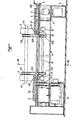
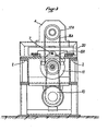
- a frame 1 made for example from U-shaped profiles 2 assembled securely, thus having the necessary rigidity, supports a longitudinal bench 3 on which is mounted a fixed headstock 4. This is equipped with a hollow spindle and a mandrel; these two bodies are not visible in the figures.
- the bench 3 also supports a movable headstock 5 but, contrary to what is usual, this movable headstock 5 is also equipped with a hollow spindle and a mandrel.
- the two spindles and the two mandrels are arranged in alignment, coaxially.
- the two dolls 4 and 5 are substantially identical; they are mounted, symmetrically to each other on the bench 3.
- the headstock 5 is mounted to be moved on the bench 3, preferably by means of a nut 6 which is fixed to it and in which is engaged a screw 7.
- the latter is supported longitudinally by bearings 8A, 8B carried by the bench 3.
- the screw 7 is provided with an operating wheel.
- This means of moving the movable headstock 5 is known per se and could be replaced by any equivalent suitable means enabling the movable headstock 5 to be brought closer and further away from the fixed headstock 4.
- a motor 10 which is coupled via a speed variator 11 to a bar 12 for driving in rotation.
- This bar 12 is supported below the bench 3 in bearings 13, 14; it is preferable that it extends over the entire maximum distance which can separate the dolls 4, 5.
- the rotational drive bar 12 carries a pulley 15A which is joined by a belt 16A to a pulley 17A. The latter is coupled in rotation by means not shown to the spindle guided in the fixed headstock 4. But contrary to what is usual, the pulley 17 is located on the side of the headstock 4 which is turned towards the movable headstock 5.
- a pulley 17B which is rotatably coupled to the guided spindle in the headstock 5.
- a yard line 16B connects this pulley 17B to a pulley 15B mounted on the rotary drive bar 12.
- the pulley 15B is locked in rotation and displaceable in translation on the bar 12.
- a telescope to be followed 18 is fixed by a bracket 19 below the movable headstock 5 to contain and guide the bar 12.
- the belt 16B and the bracket 19 can accompany the movable headstock 5 thanks to a longitudinal central recess 20 formed in the bench 3.
- Each of the dolls 4, 5 is associated respectively with what is called here a strut 20, 21, although the strag 20 is joined to the doll 4 and it is fixed like this relative to the bench 3.
- the strut 21 is joined to the doll 5 and it is movable with it. More precisely, the nut 6 is attached to the underside of the stretcher 21 and it is through the latter that the headstock 6 is moved on the bench 3.
- the stragglers 20, 21 are both outside the gap between the dolls 4, 5.
- Each straggler 20, 21 carries a tool carriage 22, 23, of a type known per se, which is movable in direction transverse and in longitudinal direction thanks to suitable slides (not shown).
- each tool holder 22, 23 includes an orientable part as is known. Tool holders of this kind are commercially available; there is no need to describe them further. It will be noted that the tool holders 22, 23 could be supported directly by the longitudinal bench 3.
- the dolls 4, 5 have not been described in detail; it does not seem necessary that they are. Indeed, we have known for a long time on the spindles hollow spindles through which we can pass workpieces, on turning lathes, for example. Clamping chucks have also been known for a long time which can be passed through by parts to be clamped. In addition, on the turning lathes the spindles are associated with collets which ensure the rotational drive of the bars to be machined. Consequently, it is possible to adopt known means for producing the dolls 4,5. However, it will be recognized that it is useful to use dolls 4, 5 having a dimension as small as possible in the longitudinal direction of the bench 3.
Landscapes
- Engineering & Computer Science (AREA)
- Mechanical Engineering (AREA)
- Turning (AREA)
Priority Applications (1)
| Application Number | Priority Date | Filing Date | Title |
|---|---|---|---|
| EP82400962A EP0095006A1 (de) | 1982-05-25 | 1982-05-25 | Drehbank zum Zentrieren und Entgraten von Werkstückenden |
Applications Claiming Priority (1)
| Application Number | Priority Date | Filing Date | Title |
|---|---|---|---|
| EP82400962A EP0095006A1 (de) | 1982-05-25 | 1982-05-25 | Drehbank zum Zentrieren und Entgraten von Werkstückenden |
Publications (1)
| Publication Number | Publication Date |
|---|---|
| EP0095006A1 true EP0095006A1 (de) | 1983-11-30 |
Family
ID=8189912
Family Applications (1)
| Application Number | Title | Priority Date | Filing Date |
|---|---|---|---|
| EP82400962A Ceased EP0095006A1 (de) | 1982-05-25 | 1982-05-25 | Drehbank zum Zentrieren und Entgraten von Werkstückenden |
Country Status (1)
| Country | Link |
|---|---|
| EP (1) | EP0095006A1 (de) |
Cited By (1)
| Publication number | Priority date | Publication date | Assignee | Title |
|---|---|---|---|---|
| EP1034881A1 (de) * | 1999-03-11 | 2000-09-13 | Hsuan-Lung Wu | CNC-Werkzeugmaschine für die gleichzeitige Endbearbeitung beider Enden eines Werkstücks |
Citations (5)
| Publication number | Priority date | Publication date | Assignee | Title |
|---|---|---|---|---|
| BE657841A (de) * | ||||
| DE46649C (de) * | J. PATRICK in Frankfurt a. M | Körner-Vorrichtung | ||
| DE939788C (de) * | 1951-11-24 | 1956-03-01 | Auto Heinen | Plandreh- und Zentriermaschine |
| CH347696A (fr) * | 1958-04-09 | 1960-07-15 | Technicum Neuchatelois | Machine-outil |
| DE1477479A1 (de) * | 1962-09-22 | 1969-03-13 | Kehr & Wichmann | Zentrier- und Glaettvorrichtung |
-
1982
- 1982-05-25 EP EP82400962A patent/EP0095006A1/de not_active Ceased
Patent Citations (5)
| Publication number | Priority date | Publication date | Assignee | Title |
|---|---|---|---|---|
| BE657841A (de) * | ||||
| DE46649C (de) * | J. PATRICK in Frankfurt a. M | Körner-Vorrichtung | ||
| DE939788C (de) * | 1951-11-24 | 1956-03-01 | Auto Heinen | Plandreh- und Zentriermaschine |
| CH347696A (fr) * | 1958-04-09 | 1960-07-15 | Technicum Neuchatelois | Machine-outil |
| DE1477479A1 (de) * | 1962-09-22 | 1969-03-13 | Kehr & Wichmann | Zentrier- und Glaettvorrichtung |
Cited By (1)
| Publication number | Priority date | Publication date | Assignee | Title |
|---|---|---|---|---|
| EP1034881A1 (de) * | 1999-03-11 | 2000-09-13 | Hsuan-Lung Wu | CNC-Werkzeugmaschine für die gleichzeitige Endbearbeitung beider Enden eines Werkstücks |
Similar Documents
| Publication | Publication Date | Title |
|---|---|---|
| EP1193013B1 (de) | Maschine zum bohren von öllöchern in kurbelwellen und dessen methode | |
| CH636543A5 (fr) | Machine-outil comprenant deux broches coaxiales opposees. | |
| FR2526342A1 (fr) | Tour automatique revolver multibroche | |
| FR2558401A1 (fr) | Machine-outil capable d'executer des operations d'usinage de differents types, tels que tournage, fraisage et percage | |
| FR2978365A1 (fr) | Machine-outil pour l'usinage de pieces en forme d'arbres et de pieces entrainees en rotation | |
| FR2565139A1 (fr) | Machine-outil a deux broches porte-piece | |
| CN113523805A (zh) | 细长工件加工用专用机床 | |
| FR2612438A1 (fr) | Machine-outil, notamment perceuse ou taraudeuse | |
| CZ120798A3 (cs) | Zařízení k obrábění konců trubek | |
| EP0095006A1 (de) | Drehbank zum Zentrieren und Entgraten von Werkstückenden | |
| FR2501087A1 (fr) | Tour a percer les centres et chanfreiner les bouts des pieces a tourner | |
| EP1740345A1 (de) | Vorrichtung und verfahren zur bearbeitung von langen, zwischen zwei sich drehenden lagern befestigten werkstücken | |
| FR2630943A1 (fr) | Tour pour l'usinage simultane de deux surfaces disposees en opposition l'une par rapport a l'autre | |
| FR2473924A1 (fr) | Tour a broche horizontale | |
| JP2007044792A (ja) | 長物加工用工作機械 | |
| US3903765A (en) | Simplified lathe | |
| EP0437412A1 (de) | Vorrichtung zum Schleifen von Spiralbohrern | |
| CN217513382U (zh) | 一种用于转向轴承套圈加工的倒角装置 | |
| FR2697192A1 (fr) | Machine-outil pour l'usinage par enlèvement de copeaux. | |
| EP0627969A1 (de) | Verfahren und vorrichtung zum wälzschälen. | |
| US943467A (en) | Centering-machine. | |
| US380785A (en) | boaert | |
| FR2599284A1 (fr) | Tour automatique a decolleter. | |
| CH610797A5 (en) | Machine tool | |
| EP0203875B1 (de) | Aufbau einer Werkzeugmaschine |
Legal Events
| Date | Code | Title | Description |
|---|---|---|---|
| PUAI | Public reference made under article 153(3) epc to a published international application that has entered the european phase |
Free format text: ORIGINAL CODE: 0009012 |
|
| 17P | Request for examination filed |
Effective date: 19820603 |
|
| AK | Designated contracting states |
Designated state(s): BE DE GB IT |
|
| STAA | Information on the status of an ep patent application or granted ep patent |
Free format text: STATUS: THE APPLICATION HAS BEEN REFUSED |
|
| 18R | Application refused |
Effective date: 19860404 |
|
| RIN1 | Information on inventor provided before grant (corrected) |
Inventor name: SCHULLIGEN, DENIS Inventor name: ROMANO, JOSEPH |