EP0094894A1 - Construction hoist - Google Patents
Construction hoist Download PDFInfo
- Publication number
- EP0094894A1 EP0094894A1 EP83420080A EP83420080A EP0094894A1 EP 0094894 A1 EP0094894 A1 EP 0094894A1 EP 83420080 A EP83420080 A EP 83420080A EP 83420080 A EP83420080 A EP 83420080A EP 0094894 A1 EP0094894 A1 EP 0094894A1
- Authority
- EP
- European Patent Office
- Prior art keywords
- mast
- sheet metal
- panels
- cabin
- assembly
- Prior art date
- Legal status (The legal status is an assumption and is not a legal conclusion. Google has not performed a legal analysis and makes no representation as to the accuracy of the status listed.)
- Granted
Links
Images


Classifications
-
- B—PERFORMING OPERATIONS; TRANSPORTING
- B66—HOISTING; LIFTING; HAULING
- B66B—ELEVATORS; ESCALATORS OR MOVING WALKWAYS
- B66B9/00—Kinds or types of lifts in, or associated with, buildings or other structures
- B66B9/16—Mobile or transportable lifts specially adapted to be shifted from one part of a building or other structure to another part or to another building or structure
- B66B9/187—Mobile or transportable lifts specially adapted to be shifted from one part of a building or other structure to another part or to another building or structure with a liftway specially adapted for temporary connection to a building or other structure
-
- Y—GENERAL TAGGING OF NEW TECHNOLOGICAL DEVELOPMENTS; GENERAL TAGGING OF CROSS-SECTIONAL TECHNOLOGIES SPANNING OVER SEVERAL SECTIONS OF THE IPC; TECHNICAL SUBJECTS COVERED BY FORMER USPC CROSS-REFERENCE ART COLLECTIONS [XRACs] AND DIGESTS
- Y10—TECHNICAL SUBJECTS COVERED BY FORMER USPC
- Y10S—TECHNICAL SUBJECTS COVERED BY FORMER USPC CROSS-REFERENCE ART COLLECTIONS [XRACs] AND DIGESTS
- Y10S187/00—Elevator, industrial lift truck, or stationary lift for vehicle
- Y10S187/90—Temporary construction elevator for building
Definitions
- the present invention relates to a rack or cable site lift, that is to say a lift or elevator, of the type comprising a mast of polygonal section, generally rectangular or square, composed of assemblable elements and intended to be moored against the exterior face of a construction as it rises and two angles of the same face of which constitute the raceways of a cabin in which personnel and / or equipment can take place, means such as that rack or cable being provided to allow the cabin to be moved along the aforementioned face of the mast and to be stopped at any desired level.
- a rack or cable site lift that is to say a lift or elevator, of the type comprising a mast of polygonal section, generally rectangular or square, composed of assemblable elements and intended to be moored against the exterior face of a construction as it rises and two angles of the same face of which constitute the raceways of a cabin in which personnel and / or equipment can take place, means such as that rack or cable being provided to allow the cabin to be moved along the aforementioned face of the mast and to
- each element of the mast forms a monobloc assembly constituted by tubular parts assembled by welding and of which at least two angles are constituted by tubes of square or rectangular section, free on at least three of their faces, each of which receives at least one support or guide roller, carried by the cabin.
- each element ends in a cross section perpendicular to its longitudinal axis and that, consequently, all the joints between successive elements are contained in planes orthogonal to this longitudinal axis, which does not contribute to a good flexural strength of the mast.
- the mast is constituted by the assembly of sheet metal panels, each of which corresponds substantially to a section of one of its lateral faces and the edges of which longitudinal are bent and drilled with rows of holes for its assembly to the sheet metal panels of the adjacent faces, with care along the edges of the same face, bearing for the rollers of the cabin, the panels of the same face of the mast being offset longitudinally relative to the panels of the other faces of this mast, so that each joint between two panels of one face is at a different level from the joints panels on the other sides.
- this mast by sheets, each of which corresponds only to one of its faces allows, by a judicious offset of the sheets of two adjacent faces, to offset their respective joint planes and, consequently, avoid the mast having transverse joint planes weakening its stiffness.
- each sheet metal panel constituting a section of one of the faces of the mast has longitudinal edges bent at 90 ° and the raceways for the rollers of the cabin are constituted by folded sheet metal profiles having two longitudinal assembly wings folded at 90 ° relative to each other and rows of holes having the same distribution as those of the sheet metal panels of the lateral faces of the mast, so as to allow their assembly using the same bolts.
- the sheet metal panels of the four faces of the mast are identical, which facilitates the storage and mounting of these panels.
- the raceways for the rollers of the cabin consist of longitudinal ribs obtained by bends and counter-bends made between the central core and the assembly wings folded 90 ° sheet metal panels corresponding to the face of the mast along which the cabin moves.
- the sheet metal panels making up the mast have transverse ribs allowing their stiffening and bosses allowing the fixing of a rack.
- each sheet metal panel has an angled-shaped stamp allowing its clamping simultaneously with the corresponding edges of the adjacent panel, using flanges having a profile complementary to that of the two stamps placed end at the end.
- the bolt through holes in the sheet metal panels as well as in the wings of the profiles possibly forming raceways are formed in frustoconical bowls capable of fitting together 'one in the other.
- each raceway a single track of trapezoidal cross section intended to receive rollers of complementary section capable of ensuring, simultaneously, the support, the retention and the guidance of the cabin.
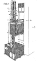
- this site lift is of the type comprising a mast (2) of square section moored against the outer face (3a) of a building (3) under construction as and when elevation of this building.
- Two angles (4) and (5) of the mast (2) adjacent to the same lateral face of this mast are arranged to present raceways for the rollers not visible in FIG. 1, of a cabin (6) intended to be moved along the aforementioned face of the mast (2) and along the face (3a) of the building (3).
- the driving of the cabin (6) along the mast (2) is ensured by the engagement of a driving pinion (7) carried by the cabin (6), in a rack (8) carried by the aforementioned face of the mast (2).
- a bracket (9), carried by the roof of the cabin (6), makes it possible to increase the height of the mast (2) as and when required during the construction of the building (3).
- the mast (2) of this elevator consists of the assembly of sheet metal panels (11) each of which corresponds substantially to a section of one of its lateral faces and whose longitudinal edges are folded over 90 ° to form assembly wings, respectively (lla) and (llb), with sparingly series of holes (12) and (13), on either side of the fold line for the passage of bolts d 'assembly (14).
- this mast (2) using sheet metal panels (11) makes it possible to offset the panels on the same side with respect to the panels on all the other sides of the mast (2) and thus obtain, at no level, the mast (2) does not have a transverse joint plane which would weaken its holding.
- the raceways (4) and (5) are formed by folded sheet sections having two longitudinal assembly wings (4a , 4b) and (5a, 5b), bent at 90 ° to each other and each of which has a series of holes (15) and (16) intended to be placed in coincidence with the rows of holes, respectively (12) and (13), located on either side of a fold line of a longitudinal edge of a panel (11), to allow the assembly of this track ment (4) or (5) to the mast (2) using the same bolts (14) used to assemble the adjacent sheet metal panels (11).
- each raceway (4) or (5) has three tracks, namely two tracks (17) and (18) parallel to each other and parallel to the plane of the face of the mast (2) along which moves the cabin (6) and a third track (19) perpendicular to the previous two.
- Each track (17) is intended to receive the support rollers (21) of the cabin (6)
- each track (18) is intended to receive the retaining rollers (22) of the cabin
- each track (19) is intended to receive the lateral guide rollers (23) of the cabin.
- FIG 4 which shows a detail of the assembly of a raceway (4), illustrates a particular and interesting characteristic of this assembly, characteristic according to which each hole (12, 13, 15, 16), formed in the panels (11) and the raceways (4) or (5), is formed in a frustoconical bowl interlocking with each other and participating in the holding of the mast, so as to reduce, if not completely eliminate, the shear forces to which the assembly bolts (14) are subjected.
- each panel (11) has along its upper and lower edges, a stamped (24) in the form of an angle, allowing its attachment to the edges facing it of the panel located above or below it, using flanges (25) composed of male (25a) and female (25b) elements joined to each other by screws (26) and having a profile complementary to that of two stampings (24) placed end to end of the two elements (11) considered.
- FIGS. 6 and 7 illustrate an alternative embodiment of this mast (2) according to which the face of the mast (2), along which the cabin (6) moves, is composed of sheet metal panels (27) each of which , between its central core constituting the aforementioned face and each of its longitudinal assembly edges (27a) and (27b), has a raceway, respectively (4) and (5) identical to the raceways (4) and ( 5) of the example illustrated by FIGS. 2 to 4.
- This arrangement reduces the number of parts to be assembled in the corresponding angles of the mast (2), but requires that the panels (27) constituting the considered face of the mast (2) be different from the panels (11) constituting its three other faces.
- the holes for the passage of the assembly bolts (14) are advantageously located in frustoconical bowls, as illustrated in FIG. 7 to, as in the previous example, relieve the bolts (14) shear forces.
- FIG. 8 shows an alternative embodiment of the raceways (4) and (5) according to which the track (19) of each raceway (4) and (5) is shaped so as to have a trapezoidal section, at instead of being flat, so that the support rollers (21) and retaining (22) and the tracks (17) and (18) corresponding thereto, can be deleted.
- the panels (11) and possibly (27), forming part of the mast (2) are advantageously perforated by windows, respectively (28) and (29) having the effect, not only to lighten them, but also to reduce their wind resistance.
- each of them has one or more bosses (31) allowing the fixing of the rack (8) without it being necessary to provide spacers forming spacers, as well as stiffening ribs (32).
Abstract
Description
La présente invention concerne un élévateur de chantier à crémaillère ou à câble, c'est-à-dire un élévateur ou ascenseur, du type comprenant un mât de section polygonale, généralement rectangulaire ou carrée, composé d'éléments assemblables et destiné à être amarré contre la face extérieure d'une construction au fur et à mesure de son élévation et dont deux angles d'une même face constituent les chemins de roulement d'une cabine dans laquelle peuvent prendre place du personnel et/ou du matériel, des moyens tels que crémaillère ou câble étant prévus pour permettre à la cabine d'être déplacée le long de la face précitée du mât et d'être stoppée à n'importe quel niveau désiré.The present invention relates to a rack or cable site lift, that is to say a lift or elevator, of the type comprising a mast of polygonal section, generally rectangular or square, composed of assemblable elements and intended to be moored against the exterior face of a construction as it rises and two angles of the same face of which constitute the raceways of a cabin in which personnel and / or equipment can take place, means such as that rack or cable being provided to allow the cabin to be moved along the aforementioned face of the mast and to be stopped at any desired level.
Dans les élévateurs connus de ce type, chaque élément du mât forme un ensemble monobloc constitué par des pièces tubulaires assemblées par soudage et dont deux angles au moins sont constitués par des tubes de section carrée ou rectangulaire, libres sur au moins trois de leurs faces, dont chacune reçoit au moins un galet d'appui ou de guidage, portés par la cabine.In known elevators of this type, each element of the mast forms a monobloc assembly constituted by tubular parts assembled by welding and of which at least two angles are constituted by tubes of square or rectangular section, free on at least three of their faces, each of which receives at least one support or guide roller, carried by the cabin.
On conçoit aisément que ces tubes formant chemins de roulement et constituant l'ossature du mât sont de section relativement importante et, par conséquent, d'un prix de revient élevé. Pour permettre l'assemblage bout à bout des éléments constitutifs dans des conditions correspondant aux nécessités d'utilisation du mât, il est indispensable que non seulement les extrémités de ces tubes soient correctement usinées, mais qu'en outre, une sur deux de ces extrémités soit équipée d'un tenon d'assemblage ce qui renchérit également le coût de fabrication.It is easily understood that these tubes forming raceways and constituting the frame of the mast are of relatively large section and, consequently, of a high cost price. To allow the end-to-end assembly of the constituent elements under conditions corresponding to the necessities of use of the mast, it is essential that not only the ends of these tubes are properly machined, but also that one in two of these ends is equipped with an assembly pin which also increases the manufacturing cost.
Il faut notamment, en outre, que chaque élément se termine par une section transversale perpendiculaire à son axe longitudinal et que, par conséquent, tous les joints entre éléments successifs soient contenus dans des plans orthogonaux à cet axe longitudinal ce qui ne contribue pas à une bonne résistance à la flexion du mât.In particular, it is also necessary that each element ends in a cross section perpendicular to its longitudinal axis and that, consequently, all the joints between successive elements are contained in planes orthogonal to this longitudinal axis, which does not contribute to a good flexural strength of the mast.
La présente invention vise à remédier à tous ces inconvénients ; à cet effet, dans l'élévateur qu'elle concerne et qui est du type précité, le mât est constitué par l'assemblage de panneaux en tôle dont chacun correspond sensiblement à un tronçon de l'une de ses faces latérales et dont les bords longitudinaux sont pliés et percés de rangées de trous en vue de son assemblage aux panneaux en tôle des faces adjacentes, avec ménagement le long des bords d'une même face, des chemins de roulement pour les galets de la cabine, les panneaux d'une même face du mât étant décalés longitudinalement par rapport aux panneaux des autres faces de ce mât, de manière que chaque joint entre deux panneaux d'une face soit à un niveau différent des joints des panneaux des autres faces.The present invention aims to remedy all these drawbacks; for this purpose, in the elevator which it concerns and which is of the aforementioned type, the mast is constituted by the assembly of sheet metal panels, each of which corresponds substantially to a section of one of its lateral faces and the edges of which longitudinal are bent and drilled with rows of holes for its assembly to the sheet metal panels of the adjacent faces, with care along the edges of the same face, bearing for the rollers of the cabin, the panels of the same face of the mast being offset longitudinally relative to the panels of the other faces of this mast, so that each joint between two panels of one face is at a different level from the joints panels on the other sides.
Il en résulte que la constitution de ce mât par des tôles dont chacune ne correspond qu'à l'une de ses faces permet, par un décalage judicieux des tôles de deux faces adjacentes, de décaler leurs plans de joints respectifs et, par conséquent, d'éviter que le mât ne présente des plans de joints transversaux affaiblissant sa raideur.It follows that the constitution of this mast by sheets, each of which corresponds only to one of its faces allows, by a judicious offset of the sheets of two adjacent faces, to offset their respective joint planes and, consequently, avoid the mast having transverse joint planes weakening its stiffness.
Suivant une première forme d'exécution de l'invention, chaque panneau en tôle constituant un tronçon de l'une des faces du mât présente des bords longitudinaux pliés à 90° et les chemins de roulement pour les galets de la cabine sont constitués par des profilés en tôle pliée présentant deux ailes longitudinales d'assemblage pliées à 90° l'une par rapport à l'autre et des rangées de trous ayant la même répartition que ceux des panneaux en tôle des faces latérales du mât, de manière à permettre leur assemblage à l'aide des mêmes boulons.According to a first embodiment of the invention, each sheet metal panel constituting a section of one of the faces of the mast has longitudinal edges bent at 90 ° and the raceways for the rollers of the cabin are constituted by folded sheet metal profiles having two longitudinal assembly wings folded at 90 ° relative to each other and rows of holes having the same distribution as those of the sheet metal panels of the lateral faces of the mast, so as to allow their assembly using the same bolts.
Grâce à cette disposition, les panneaux en tôle des quatre faces du mât sont identiques ce qui facilite le stockage et le montage de ces panneaux.Thanks to this arrangement, the sheet metal panels of the four faces of the mast are identical, which facilitates the storage and mounting of these panels.
Suivant une variante d'exécution de l'invention, les chemins de roulement pour les galets de la cabine sont constitués par des nervures longitudinales obtenues par des pliages et contre-pliages réalisés entre l'âme centrale et les ailes d'assemblage pliées à 90° des panneaux en tôle correspondant à la face du mât le long de laquelle se déplace la cabine.According to an alternative embodiment of the invention, the raceways for the rollers of the cabin consist of longitudinal ribs obtained by bends and counter-bends made between the central core and the assembly wings folded 90 ° sheet metal panels corresponding to the face of the mast along which the cabin moves.
Dans ce cas, seuls les panneaux en tôle constituant les trois autres faces du mât peuvent être identiques.In this case, only the sheet metal panels constituting the other three faces of the mast can be identical.
Naturellement, les panneaux en tôle composant le mât présentent des nervures transversales permettant leur raidissement et des bossages permettant la fixation d'une crémaillère.Naturally, the sheet metal panels making up the mast have transverse ribs allowing their stiffening and bosses allowing the fixing of a rack.
De préférence, les bords libres transversaux d'assemblage de chaque panneau en tôle présentent un embouti en forme de cornière permettant son bridage simultanément aux bords correspondants du panneau adjacent, à l'aide de brides présentant un profil complémentaire à celui des deux emboutis placés bout à bout.Preferably, the transverse free assembly edges of each sheet metal panel have an angled-shaped stamp allowing its clamping simultaneously with the corresponding edges of the adjacent panel, using flanges having a profile complementary to that of the two stamps placed end at the end.
Suivant une forme d'exécution intéressante de l'invention, pour éviter le risque de glissement l'une sur l'autre des ailes d'assemblage des panneaux en tôle et éventuellement, des profilés en tôle pliée formant chemins de roulement et ayant pour effet d'engendrer des efforts de cisaillement dans les boulons d'assemblage, les trous de passage des boulons dans les panneaux en tôle ainsi que dans les ailes des profilés formant éventuellement chemins de roulement, sont ménagés dans des cuvettes tronconiques aptes à s'emboîter l'une dans l'autre.According to an advantageous embodiment of the invention, to avoid the risk of sliding one over the other of the assembly wings of the sheet metal panels and possibly, folded sheet metal profiles forming raceways and having the effect to generate shear forces in the assembly bolts, the bolt through holes in the sheet metal panels as well as in the wings of the profiles possibly forming raceways, are formed in frustoconical bowls capable of fitting together 'one in the other.
Suivant encore une caractéristique intéressante de l'invention, pour alléger les panneaux en tôle formant chaque face du mât, il est prévu des évidements pouvant occuper chaque partie de panneau en tôle non nervurée. La présence de ces évidements présente en outre, l'avantage de diminuer la prise au vent.According to yet another advantageous characteristic of the invention, to lighten the sheet metal panels forming each face of the mast, there are provided recesses which can occupy each part of the panel in non-ribbed sheet metal. The presence of these recesses also has the advantage of reducing the wind resistance.
Suivant encore une autre caractéristique de l'invention, il est prévu pour chaque chemin de roulement, une seule piste de section transversale trapézoïdale destinée à recevoir des galets de section complémentaire aptes à assurer, simultanément, l'appui, la retenue et le guidage de la cabine.According to yet another characteristic of the invention, there is provided for each raceway, a single track of trapezoidal cross section intended to receive rollers of complementary section capable of ensuring, simultaneously, the support, the retention and the guidance of the cabin.
De toute façon, l'invention sera bien comprise à l'aide de la description qui suit, en référence aux dessins schématiques annexés, représentant, à titre d'exemples non limitatifs, quelques formes d'exécution de cet élévateur :
- Figure 1 en est une vue en perspective ;
- Figure 2 est, à échelle agrandie, une vue en coupe transversale du mât de l'élévateur de figure 1 ;
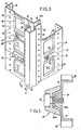
- Figure 3 est une vue partielle en perspective d'un tronçon du mât de figure 1 ;
- Figure 4 est une vue en coupe suivant 4-4 de figure 3 montrant, à échelle agrandie, un mode de réalisation des chemins de roulement le long d'un des angles du mât de figure 3 ;
- Figure 5 est une vue en coupe suivant 5-5 de figure 3 montrant le mode d'assemblage des bords horizontaux des deux panneaux superposés ; J
- Figure 6 est une vue simplifiée correspondant à figure 2, illustrant une variante d'exécution de ce mât ;
- Figure 7 est une vue en coupe similaire à figure 4, montrant le mode d'assemblage des chemins de roulement à l'un des angles du mât, conformément à l'objet de figure 6 ;
- Figure 8 est une vue partielle en coupe transversale montrant une forme d'exécution particulière d'un chemin de roulement.
- Figure 1 is a perspective view;
- Figure 2 is, on an enlarged scale, a cross-sectional view of the mast of the elevator of Figure 1;
- Figure 3 is a partial perspective view of a section of the mast of Figure 1;
- Figure 4 is a sectional view along 4-4 of Figure 3 showing, on an enlarged scale, an embodiment of the raceways along one of the angles of the mast of Figure 3;
- Figure 5 is a sectional view along 5-5 of Figure 3 showing the method of assembling the horizontal edges of the two superimposed panels; J
- Figure 6 is a simplified view corresponding to Figure 2, illustrating an alternative embodiment of this mast;
- Figure 7 is a sectional view similar to Figure 4, showing the method of assembling the raceways at one of the angles of the mast, in accordance with the object of figure 6;
- Figure 8 is a partial cross-sectional view showing a particular embodiment of a raceway.
Comme le montre la figure 1, cet élévateur de chantier est du type comprenant un mât (2) de section carrée amarré contre la face extérieure (3a) d'un immeuble (3) en cours de construction au fur et à mesure de l'élévation de cet immeuble.As shown in Figure 1, this site lift is of the type comprising a mast (2) of square section moored against the outer face (3a) of a building (3) under construction as and when elevation of this building.
Deux angles (4) et (5) du mât (2) adjacents à une même face latérale de ce mât sont agencés pour présenter des chemins de roulement pour les galets non visibles sur la figure 1, d'une cabine (6) destinée à être déplacée le long de la face précitée du mât (2) et le long de la face (3a) de l'immeuble (3). L'entraînement de la cabine (6) le long du mât (2) est assuré par l'engrènement d'un pignon moteur (7) porté par la cabine (6), dans une crémaillère (8) portée par la face précitée du mât (2). Une potence (9), portée par le toit de la cabine (6), permet d'augmenter la hauteur du mât (2) au fur et à mesure des besoins au cours de la construction de l'immeuble (3).Two angles (4) and (5) of the mast (2) adjacent to the same lateral face of this mast are arranged to present raceways for the rollers not visible in FIG. 1, of a cabin (6) intended to be moved along the aforementioned face of the mast (2) and along the face (3a) of the building (3). The driving of the cabin (6) along the mast (2) is ensured by the engagement of a driving pinion (7) carried by the cabin (6), in a rack (8) carried by the aforementioned face of the mast (2). A bracket (9), carried by the roof of the cabin (6), makes it possible to increase the height of the mast (2) as and when required during the construction of the building (3).
Comme le montre le dessin, le mât (2) de cet élévateur est constitué par l'assemblage de panneaux en tôle (11) dont chacun correspond sensiblement à un tronçon de l'une de ses faces latérales et dont les bords longitudinaux sont repliés à 90° pour former des ailes d'assemblage, respectivement (lla) et (llb), avec ménagement de séries de trous (12) et (13), de part et d'autre de la ligne de pliage pour le passage de boulons d'assemblage (14).As shown in the drawing, the mast (2) of this elevator consists of the assembly of sheet metal panels (11) each of which corresponds substantially to a section of one of its lateral faces and whose longitudinal edges are folded over 90 ° to form assembly wings, respectively (lla) and (llb), with sparingly series of holes (12) and (13), on either side of the fold line for the passage of bolts d 'assembly (14).
Comme le montrent notamment les figures 1 et 3, la constitution de ce mât (2) à l'aide de panneaux en tôle (11), permet de décaler les panneaux d'une même face par rapport aux panneaux de toutes les autres faces du mât (2) et d'obtenir ainsi, qu'à aucun niveau, le mât (2) ne présente un plan de joint transversal qui affaiblirait sa tenue.As shown in particular in FIGS. 1 and 3, the constitution of this mast (2) using sheet metal panels (11) makes it possible to offset the panels on the same side with respect to the panels on all the other sides of the mast (2) and thus obtain, at no level, the mast (2) does not have a transverse joint plane which would weaken its holding.
Dans la première forme d'exécution de ce mât, telle qu'illustrée sur les figures 2 à 4, les chemins de roulement (4) et (5) sont constitués par des profilés en tôle pliée présentant deux ailes longitudinales d'assemblage (4a, 4b) et (5a, 5b), pliées à 90° l'une par rapport à l'autre et dont chacune présente une série de trous (15) et (16) destinés à être mis en coïncidence avec les rangées de trous, respectivement (12) et (13), situés de part et d'autre d'une ligne de pliage d'un bord longitudinal d'un panneau (11), pour permettre l'assemblage de ce chemin de roulement (4) ou (5) au mât (2) à l'aide des mêmes boulons (14) servant à l'assemblage des panneaux en tôle (11) adjacents.In the first embodiment of this mast, as illustrated in FIGS. 2 to 4, the raceways (4) and (5) are formed by folded sheet sections having two longitudinal assembly wings (4a , 4b) and (5a, 5b), bent at 90 ° to each other and each of which has a series of holes (15) and (16) intended to be placed in coincidence with the rows of holes, respectively (12) and (13), located on either side of a fold line of a longitudinal edge of a panel (11), to allow the assembly of this track ment (4) or (5) to the mast (2) using the same bolts (14) used to assemble the adjacent sheet metal panels (11).
Dans cet exemple, chaque chemin de roulement (4) ou (5) présente trois pistes, à savoir deux pistes (17) et (18) parallèles entre elles et parallèles au plan de la face du mât (2) le long de laquelle se déplace la cabine (6) et une troisième piste (19) perpendiculaire aux deux précédentes. Chaque piste (17) est destinée à recevoir les galets d'appui (21) de la cabine (6), chaque piste (18) est destinée à recevoir les galets de retenue (22) de la cabine et chaque piste (19) est destinée à recevoir les galets de guidage latéral (23) de la cabine.In this example, each raceway (4) or (5) has three tracks, namely two tracks (17) and (18) parallel to each other and parallel to the plane of the face of the mast (2) along which moves the cabin (6) and a third track (19) perpendicular to the previous two. Each track (17) is intended to receive the support rollers (21) of the cabin (6), each track (18) is intended to receive the retaining rollers (22) of the cabin and each track (19) is intended to receive the lateral guide rollers (23) of the cabin.
Dans l'exemple qui vient d'être décrit, on voit que les panneaux (11) de chaque face du mât (2) sont identiques ce qui simplifie la fabrication et le stockage des éléments constitutifs du mât.In the example which has just been described, it can be seen that the panels (11) on each face of the mast (2) are identical, which simplifies the manufacture and storage of the components of the mast.
La figure 4 qui montre un détail de l'assemblage d'un chemin de roulement (4), illustre une caractéristique particulière et intéressante de cet assemblage, caractéristique selon laquelle chaque trou (12, 13, 15, 16), ménagé dans les panneaux (11) et les chemins de roulement (4) ou (5), est ménagé dans une cuvette tronconique s'emboîtant mutuellement l'une dans l'autre et participant à la tenue du mât, de manière à réduire, sinon éliminer totalement, les efforts de cisaillement auxquels sont soumis les boulons d'assemblage (14).Figure 4 which shows a detail of the assembly of a raceway (4), illustrates a particular and interesting characteristic of this assembly, characteristic according to which each hole (12, 13, 15, 16), formed in the panels (11) and the raceways (4) or (5), is formed in a frustoconical bowl interlocking with each other and participating in the holding of the mast, so as to reduce, if not completely eliminate, the shear forces to which the assembly bolts (14) are subjected.
Comme le montrent notamment les figures 3 et 5, chaque panneau (11) présente le long de ses bords supérieur et inférieur, un embouti (24) en forme de cornière, autorisant son attache aux bords lui faisant face du panneau situé au-dessus ou au-dessous de lui, à l'aide de brides (25) composées d'éléments mâle (25a) et femelle (25b) assemblés l'un à l'autre par des vis (26) et présentant un profil complémentaire de celui des deux emboutis (24) placés bout à bout des deux éléments (11) considérés.As shown in particular in Figures 3 and 5, each panel (11) has along its upper and lower edges, a stamped (24) in the form of an angle, allowing its attachment to the edges facing it of the panel located above or below it, using flanges (25) composed of male (25a) and female (25b) elements joined to each other by screws (26) and having a profile complementary to that of two stampings (24) placed end to end of the two elements (11) considered.
Les figures 6 et 7 illustrent une variante d'exécution de ce mât (2) selon laquelle la face du mât (2), le long de laquelle se déplace la cabine (6), est composée de panneaux en tôle (27) dont chacun, entre son âme centrale constituant la face précitée et chacun de ses bords longitudinaux d'assemblage (27a) et (27b), présente un chemin de roulement, respectivement (4) et (5) identique aux chemins de roulement (4) et (5) de l'exemple illustré par les figures 2 à 4. Cette disposition diminue le nombre de pièces à assembler dans les angles correspondants du mât (2), mais impose que les panneaux (27) constituant la face considérée du mât (2) soient différents des panneaux (11) constituant ses trois autres faces.Figures 6 and 7 illustrate an alternative embodiment of this mast (2) according to which the face of the mast (2), along which the cabin (6) moves, is composed of sheet metal panels (27) each of which , between its central core constituting the aforementioned face and each of its longitudinal assembly edges (27a) and (27b), has a raceway, respectively (4) and (5) identical to the raceways (4) and ( 5) of the example illustrated by FIGS. 2 to 4. This arrangement reduces the number of parts to be assembled in the corresponding angles of the mast (2), but requires that the panels (27) constituting the considered face of the mast (2) be different from the panels (11) constituting its three other faces.
Dans cette forme d'exécution comme dans la précédente, les trous pour le passage des boulons d'assemblage (14) sont avantageusement situés dans des cuvettes tronconiques, comme illustré sur la figure 7 pour, comme dans l'exemple précédent, soulager les boulons (14) des efforts de cisaillement.In this embodiment as in the previous one, the holes for the passage of the assembly bolts (14) are advantageously located in frustoconical bowls, as illustrated in FIG. 7 to, as in the previous example, relieve the bolts (14) shear forces.
La figure 8 montre une variante d'exécution des chemins de roulement (4) et (5) selon laquelle la piste (19) de chaque chemin de roulement (4) et (5) est conformée de manière à présenter une section trapézoïdale, au lieu d'être plane, de telle sorte que les galets d'appui (21) et de retenue (22) et les pistes (17) et (18) leur correspondant, peuvent être supprimés.FIG. 8 shows an alternative embodiment of the raceways (4) and (5) according to which the track (19) of each raceway (4) and (5) is shaped so as to have a trapezoidal section, at instead of being flat, so that the support rollers (21) and retaining (22) and the tracks (17) and (18) corresponding thereto, can be deleted.
Comme cela ressort des figures 1 et 3, les panneaux (11) et éventuellement (27), entrant dans la constitution du mât (2), sont avantageusement ajourés par des fenêtres, respectivement (28) et (29) ayant pour effet, non seulement de les alléger, mais aussi de réduire leur prise au vent. En outre, chacun d'eux présente un ou plusieurs bossages (31) permettant la fixation de la crémaillère (8) sans qu'il soit nécessaire de prévoir des cales formant entretoises, ainsi que des nervures de raidissement (32).As is apparent from Figures 1 and 3, the panels (11) and possibly (27), forming part of the mast (2), are advantageously perforated by windows, respectively (28) and (29) having the effect, not only to lighten them, but also to reduce their wind resistance. In addition, each of them has one or more bosses (31) allowing the fixing of the rack (8) without it being necessary to provide spacers forming spacers, as well as stiffening ribs (32).
Comme il va de soi et comme il res .ort de ce qui précède, la présente invention ne se limite pas aux seules formes d'exécution décrites ci-dessus à titre d'exemples non limitatifs ; elle en embrasse, au contraire, toutes les variantes d'exécution.As it goes without saying and as is clear from the above, the present invention is not limited to the sole embodiments described above by way of nonlimiting examples; on the contrary, it embraces all variants of execution.
Claims (9)
Priority Applications (1)
| Application Number | Priority Date | Filing Date | Title |
|---|---|---|---|
| AT83420080T ATE15177T1 (en) | 1982-05-11 | 1983-05-04 | CONSTRUCTION ELEVATOR. |
Applications Claiming Priority (2)
| Application Number | Priority Date | Filing Date | Title |
|---|---|---|---|
| FR8208740 | 1982-05-11 | ||
| FR8208740A FR2526774B1 (en) | 1982-05-11 | 1982-05-11 | CONSTRUCTION ELEVATOR |
Publications (2)
| Publication Number | Publication Date |
|---|---|
| EP0094894A1 true EP0094894A1 (en) | 1983-11-23 |
| EP0094894B1 EP0094894B1 (en) | 1985-08-28 |
Family
ID=9274176
Family Applications (1)
| Application Number | Title | Priority Date | Filing Date |
|---|---|---|---|
| EP83420080A Expired EP0094894B1 (en) | 1982-05-11 | 1983-05-04 | Construction hoist |
Country Status (6)
| Country | Link |
|---|---|
| US (1) | US4557353A (en) |
| EP (1) | EP0094894B1 (en) |
| JP (1) | JPS58202276A (en) |
| AT (1) | ATE15177T1 (en) |
| DE (1) | DE3360661D1 (en) |
| FR (1) | FR2526774B1 (en) |
Cited By (2)
| Publication number | Priority date | Publication date | Assignee | Title |
|---|---|---|---|---|
| EP0510528A2 (en) * | 1991-04-23 | 1992-10-28 | Langer geb. Layher, Ruth | Lift for building materials and elements of trestle work |
| WO1997022768A1 (en) * | 1995-09-22 | 1997-06-26 | Paul Lingen | Mast for a building scaffold or hoist |
Families Citing this family (33)
| Publication number | Priority date | Publication date | Assignee | Title |
|---|---|---|---|---|
| US4804308A (en) * | 1987-01-20 | 1989-02-14 | Motor Coach Industries | Wheelchair lift |
| US5253734A (en) * | 1992-03-11 | 1993-10-19 | Laurutis Charles J | High rise emergency elevator |
| US6079520A (en) * | 1995-04-07 | 2000-06-27 | Infinite Access Corporation | Method of retro-fitting elevators to existing buildings |
| US5626208A (en) * | 1995-07-13 | 1997-05-06 | Sprague; Randy L. | Lift assembly |
| US5927440A (en) * | 1996-09-11 | 1999-07-27 | Freeman; Glen D. | Mobile hoist system and method |
| KR100260648B1 (en) * | 1997-11-27 | 2000-12-01 | 노희상 | Safe fence for construction |
| WO1999040013A1 (en) * | 1998-02-06 | 1999-08-12 | Jetwey Technology Corporation Limited | Elevator |
| US6779634B1 (en) * | 1999-12-06 | 2004-08-24 | Wayne M. Slagle | Dumb waiter elevating and lowering platform device |
| US6640934B1 (en) * | 2000-05-01 | 2003-11-04 | Ricky L. Edwards | Residential cargo lift |
| US20020139619A1 (en) * | 2000-05-16 | 2002-10-03 | Minglun Qiu | Hoistwayless elevator system |
| ES2170680B1 (en) * | 2000-07-06 | 2004-01-01 | Ttv Madrid S L | REMOVABLE CLOSURE STRUCTURE FOR ELEVATORS. |
| KR100371052B1 (en) * | 2000-08-05 | 2003-02-06 | 주식회사 이성건설기계 | elevator |
| KR20020033672A (en) * | 2002-02-23 | 2002-05-07 | 백수곤 | Boom hoist |
| US20030178259A1 (en) * | 2002-03-25 | 2003-09-25 | Henderson Russell Peter | Goods lift mechanism |
| JP4231842B2 (en) * | 2002-06-20 | 2009-03-04 | オーチス エレベータ カンパニー | Upper safety fence for machine room-less elevator car |
| US7392624B2 (en) * | 2003-02-05 | 2008-07-01 | Dwight Eric Kinzer | Modular load-bearing structural column |
| US20060196735A1 (en) * | 2005-03-07 | 2006-09-07 | Waupaca Elevator Company, Inc. | Frameless elevator cab and methods |
| FR2894237B1 (en) * | 2005-12-02 | 2009-05-29 | Manuel Machado | NACELLE WITH MOTOR VEHICLE PROPULSION AND SAFETY MECHANISM |
| ES2283217B1 (en) * | 2006-04-11 | 2009-02-16 | Elevadores Goian S.L. | MODULAR ELEVATOR WITH AUTOMOTIVE CABIN ON MASTIL. |
| US8020667B2 (en) * | 2006-04-21 | 2011-09-20 | Dennis Johnson | Lift apparatus |
| US20080099283A1 (en) * | 2006-10-25 | 2008-05-01 | Robert Jacobus Reigwein | Lift Apparatus and Method for Forming Same |
| US20080230321A1 (en) * | 2007-03-19 | 2008-09-25 | Frank Csaszar | Portable freestanding elevator |
| US20090129905A1 (en) * | 2007-11-20 | 2009-05-21 | International Business Machines Corporation | Portable end-to-end installation and removal service lift tool for rack mounted it equipment |
| US20090282747A1 (en) * | 2008-05-14 | 2009-11-19 | Epp Richard J | Grain bin with person elevator |
| NL2001941C (en) * | 2008-08-29 | 2010-03-11 | Houtveen Beheer Achterveld B V | VEHICLE LIFT. |
| GB0907333D0 (en) * | 2009-04-29 | 2009-06-10 | Adams William M | Lifting apparatus |
| US10597274B1 (en) * | 2011-11-15 | 2020-03-24 | Homecare Products, Inc. | Tower elevating assembly |
| JP5686121B2 (en) * | 2012-07-26 | 2015-03-18 | 村田機械株式会社 | Stacker crane |
| CN102765651A (en) * | 2012-08-05 | 2012-11-07 | 荆州市荆工机械有限公司 | People-goods dual-purpose construction lifter provided with driving mechanism on top of suspension coops and forming integral structure with suspension coop |
| JP6256420B2 (en) * | 2015-06-30 | 2018-01-10 | 村田機械株式会社 | Stacker crane |
| WO2018139924A2 (en) * | 2017-01-24 | 2018-08-02 | Raxtar B.V. | Construction elevator |
| TWI620705B (en) * | 2017-05-02 | 2018-04-11 | He cheng yu | Lifting stair structure |
| WO2021237049A1 (en) * | 2020-05-21 | 2021-11-25 | The Tisdale Group, LLC | Mast climber |
Citations (6)
| Publication number | Priority date | Publication date | Assignee | Title |
|---|---|---|---|---|
| GB285037A (en) * | 1927-02-09 | 1928-07-05 | Hans Kasch | Improvements in masts for apparatus for hoisting and pouring concrete |
| FR1568824A (en) * | 1967-12-05 | 1969-05-30 | ||
| FR2000319A1 (en) * | 1968-01-17 | 1969-09-05 | Meyer Roy | |
| FR2121081A5 (en) * | 1970-12-29 | 1972-08-18 | Rompa Jozef | |
| AT315419B (en) * | 1971-12-03 | 1974-05-27 | Alois Krasser | Tubular steel mast for construction hoists |
| FR2268929A1 (en) * | 1974-04-26 | 1975-11-21 | Ace Machinery Ltd |
Family Cites Families (7)
| Publication number | Priority date | Publication date | Assignee | Title |
|---|---|---|---|---|
| US498859A (en) * | 1893-06-06 | Niels poulson | ||
| US1552474A (en) * | 1920-11-20 | 1925-09-08 | Dornier Claude | Hollow metal beam |
| US3820906A (en) * | 1972-08-10 | 1974-06-28 | H Katt | Highway sign post |
| US3878916A (en) * | 1973-02-07 | 1975-04-22 | Jr Gerome R White | Rack and pinion drive counterbalanced hoist systems |
| FR2293893A1 (en) * | 1974-12-12 | 1976-07-09 | Telemecanique Electrique | FRAME FOR METAL CABINET |
| US4262773A (en) * | 1979-07-13 | 1981-04-21 | Basham Billy G | Portable scaffold |
| US4248025A (en) * | 1979-08-08 | 1981-02-03 | Unarco Industries, Inc. | Knock down pole construction |
-
1982
- 1982-05-11 FR FR8208740A patent/FR2526774B1/en not_active Expired
-
1983
- 1983-05-04 DE DE8383420080T patent/DE3360661D1/en not_active Expired
- 1983-05-04 AT AT83420080T patent/ATE15177T1/en not_active IP Right Cessation
- 1983-05-04 EP EP83420080A patent/EP0094894B1/en not_active Expired
- 1983-05-11 JP JP58081032A patent/JPS58202276A/en active Pending
- 1983-05-11 US US06/493,743 patent/US4557353A/en not_active Expired - Fee Related
Patent Citations (6)
| Publication number | Priority date | Publication date | Assignee | Title |
|---|---|---|---|---|
| GB285037A (en) * | 1927-02-09 | 1928-07-05 | Hans Kasch | Improvements in masts for apparatus for hoisting and pouring concrete |
| FR1568824A (en) * | 1967-12-05 | 1969-05-30 | ||
| FR2000319A1 (en) * | 1968-01-17 | 1969-09-05 | Meyer Roy | |
| FR2121081A5 (en) * | 1970-12-29 | 1972-08-18 | Rompa Jozef | |
| AT315419B (en) * | 1971-12-03 | 1974-05-27 | Alois Krasser | Tubular steel mast for construction hoists |
| FR2268929A1 (en) * | 1974-04-26 | 1975-11-21 | Ace Machinery Ltd |
Cited By (3)
| Publication number | Priority date | Publication date | Assignee | Title |
|---|---|---|---|---|
| EP0510528A2 (en) * | 1991-04-23 | 1992-10-28 | Langer geb. Layher, Ruth | Lift for building materials and elements of trestle work |
| EP0510528A3 (en) * | 1991-04-23 | 1993-01-13 | Ruth Langer Geb. Layher | Lift for building materials and elements of trestle work |
| WO1997022768A1 (en) * | 1995-09-22 | 1997-06-26 | Paul Lingen | Mast for a building scaffold or hoist |
Also Published As
| Publication number | Publication date |
|---|---|
| DE3360661D1 (en) | 1985-10-03 |
| FR2526774A1 (en) | 1983-11-18 |
| JPS58202276A (en) | 1983-11-25 |
| EP0094894B1 (en) | 1985-08-28 |
| US4557353A (en) | 1985-12-10 |
| FR2526774B1 (en) | 1986-03-07 |
| ATE15177T1 (en) | 1985-09-15 |
Similar Documents
| Publication | Publication Date | Title |
|---|---|---|
| EP0094894B1 (en) | Construction hoist | |
| EP2674538B1 (en) | Modular construction and corresponding assembly method | |
| DE19757204C1 (en) | Body cell for railway carriage superstructures | |
| EP3121087B1 (en) | Modular car of a public transport vehicle, in particular of a rail vehicle | |
| FR2547875A1 (en) | RIBBED METAL JOINT PIECE FOR REALIZING A STRUCTURAL ELEMENT OF WOOD FRAME, SUCH AS A JOIST STRUCTURE | |
| EP0864702B1 (en) | Supporting structure for buildings made from cold-rolled profiles | |
| FR3025503A1 (en) | CONSTRUCTION ASSEMBLY FOR ELEVATOR PYLON AND ELEVATOR PYLON | |
| CA2286571A1 (en) | Device for assembling wooden planks constituting structural walls | |
| EP0323293B1 (en) | Apparatus for weighing vehicles | |
| FR2544447A1 (en) | Cable supporting frame using angles and channels | |
| EP0214892B1 (en) | Framework for the realization of three-dimensional elements, particularly for attachment to buildings | |
| EP0194949B1 (en) | Utility building, especially a shopping space | |
| EP0440567A1 (en) | Simple and double girders and posts constituted by the connection of Z-shaped profiles, and permitting in particular the realization of a frame or a bracket, for use in a building's construction | |
| EP0193689B1 (en) | Prefabricated framework for the construction of walls | |
| EP0593365B1 (en) | Horizontal supporting beam as bridge part | |
| WO2013034572A1 (en) | Metal girder suitable for producing a constituent element of the beam of a bridge | |
| EP0712970B1 (en) | Façade structure for buildings or similar constructions | |
| EP0221217A1 (en) | Folding wooden framework | |
| FR2650611A1 (en) | Wooden framework for forming the walls of a structure, and structure obtained from the said framework | |
| EP0658658B1 (en) | Framework for building-panels, panel and building comprising such a framework | |
| FR2559175A1 (en) | Track structure for games such as miniature golf. | |
| FR2585048A1 (en) | Prefabricated construction | |
| FR3103203A1 (en) | Modular metal structure | |
| FR2706507A1 (en) | Facade framework for any building whatsoever and building produced with the aid of such facade frameworks | |
| EP3931405A1 (en) | Modular metal structure |
Legal Events
| Date | Code | Title | Description |
|---|---|---|---|
| PUAI | Public reference made under article 153(3) epc to a published international application that has entered the european phase |
Free format text: ORIGINAL CODE: 0009012 |
|
| AK | Designated contracting states |
Designated state(s): AT BE CH DE GB IT LI LU NL SE |
|
| 17P | Request for examination filed |
Effective date: 19831014 |
|
| ITF | It: translation for a ep patent filed |
Owner name: BARZANO' E ZANARDO MILANO S.P.A. |
|
| GRAA | (expected) grant |
Free format text: ORIGINAL CODE: 0009210 |
|
| AK | Designated contracting states |
Designated state(s): AT BE CH DE GB IT LI LU NL SE |
|
| REF | Corresponds to: |
Ref document number: 15177 Country of ref document: AT Date of ref document: 19850915 Kind code of ref document: T |
|
| REF | Corresponds to: |
Ref document number: 3360661 Country of ref document: DE Date of ref document: 19851003 |
|
| PG25 | Lapsed in a contracting state [announced via postgrant information from national office to epo] |
Ref country code: AT Effective date: 19860504 |
|
| PG25 | Lapsed in a contracting state [announced via postgrant information from national office to epo] |
Ref country code: SE Effective date: 19860505 |
|
| PG25 | Lapsed in a contracting state [announced via postgrant information from national office to epo] |
Ref country code: LU Free format text: LAPSE BECAUSE OF NON-PAYMENT OF DUE FEES Effective date: 19860531 Ref country code: LI Effective date: 19860531 Ref country code: CH Effective date: 19860531 Ref country code: BE Effective date: 19860531 |
|
| PLBE | No opposition filed within time limit |
Free format text: ORIGINAL CODE: 0009261 |
|
| STAA | Information on the status of an ep patent application or granted ep patent |
Free format text: STATUS: NO OPPOSITION FILED WITHIN TIME LIMIT |
|
| 26N | No opposition filed | ||
| BERE | Be: lapsed |
Owner name: PICHON MICHEL ALAIN Effective date: 19860531 |
|
| PG25 | Lapsed in a contracting state [announced via postgrant information from national office to epo] |
Ref country code: NL Effective date: 19861201 |
|
| NLV4 | Nl: lapsed or anulled due to non-payment of the annual fee | ||
| REG | Reference to a national code |
Ref country code: CH Ref legal event code: PL |
|
| PG25 | Lapsed in a contracting state [announced via postgrant information from national office to epo] |
Ref country code: DE Effective date: 19870203 |
|
| GBPC | Gb: european patent ceased through non-payment of renewal fee | ||
| PG25 | Lapsed in a contracting state [announced via postgrant information from national office to epo] |
Ref country code: GB Free format text: LAPSE BECAUSE OF NON-PAYMENT OF DUE FEES Effective date: 19881122 |
|
| EUG | Se: european patent has lapsed |
Ref document number: 83420080.0 Effective date: 19870225 |