EP0712970B1 - Façade structure for buildings or similar constructions - Google Patents
Façade structure for buildings or similar constructions Download PDFInfo
- Publication number
- EP0712970B1 EP0712970B1 EP19950402465 EP95402465A EP0712970B1 EP 0712970 B1 EP0712970 B1 EP 0712970B1 EP 19950402465 EP19950402465 EP 19950402465 EP 95402465 A EP95402465 A EP 95402465A EP 0712970 B1 EP0712970 B1 EP 0712970B1
- Authority
- EP
- European Patent Office
- Prior art keywords
- piece
- rail
- assembly
- façade
- rails
- Prior art date
- Legal status (The legal status is an assumption and is not a legal conclusion. Google has not performed a legal analysis and makes no representation as to the accuracy of the status listed.)
- Expired - Lifetime
Links
Images

Classifications
-
- E—FIXED CONSTRUCTIONS
- E06—DOORS, WINDOWS, SHUTTERS, OR ROLLER BLINDS IN GENERAL; LADDERS
- E06B—FIXED OR MOVABLE CLOSURES FOR OPENINGS IN BUILDINGS, VEHICLES, FENCES OR LIKE ENCLOSURES IN GENERAL, e.g. DOORS, WINDOWS, BLINDS, GATES
- E06B3/00—Window sashes, door leaves, or like elements for closing wall or like openings; Layout of fixed or moving closures, e.g. windows in wall or like openings; Features of rigidly-mounted outer frames relating to the mounting of wing frames
- E06B3/96—Corner joints or edge joints for windows, doors, or the like frames or wings
- E06B3/964—Corner joints or edge joints for windows, doors, or the like frames or wings using separate connection pieces, e.g. T-connection pieces
- E06B3/9642—Butt type joints with at least one frame member cut off square; T-shape joints
-
- E—FIXED CONSTRUCTIONS
- E04—BUILDING
- E04B—GENERAL BUILDING CONSTRUCTIONS; WALLS, e.g. PARTITIONS; ROOFS; FLOORS; CEILINGS; INSULATION OR OTHER PROTECTION OF BUILDINGS
- E04B2/00—Walls, e.g. partitions, for buildings; Wall construction with regard to insulation; Connections specially adapted to walls
- E04B2/88—Curtain walls
Definitions
- the present invention relates to a facade structure for a building or similar construction, as described, for example, in GB-A-1 211 882 or FR-A-1 395 895, in particular of the type consisting of vertical load-bearing walls, s extending according to the depth of the building from horizontal slabs delimiting the successive floors of this building, these walls and slabs together forming cells in which are distributed the dwellings or rooms to be provided in the building, at each level thereof .
- the cells thus delimited are closed by a front wall, said "mantle" wall, vertical, perpendicular to the aforementioned slabs and load-bearing walls, this wall usually comprising a panel inserted into the opening of each cell and which incorporates a support structure for elements of sound, thermal insulation and protection against water, wind and, where appropriate, fire.
- This panel is then fitted with an exterior covering or cladding, generally made of stones, bricks or the like, forming the external facade of the building.
- the present invention relates to a facade structure of an entirely different design, making it possible to arrange and distribute, directly on site, the door frames and windows inside the panel, in particular by authorizing any adjustments that may prove necessary before being immobilized and mounting between these frames the essential insulation and sealing gasket, and finally bringing back last exterior cladding for finishing and protection.
- the structure considered, to be mounted between two vertical load-bearing walls and two horizontal slabs separated by these walls, by delimiting together a cell open towards the outside in front of a building is characterized in that it comprises, arranged in the vicinity of the outer edge or nose of the slabs, two healds parallel to the plane of the external facade closing the cell, these healds, respectively high and low, being horizontal and fixed opposite on the top of the lower slab and on the bottom of the upper slab, each stringer having suspension hooks for the high stringer and for guiding and holding for the low stringer, at least one assembly part also comprising hooks cooperating with those of the struts, and at least one solid or hollow vertical profile, open at its ends in which the connecting parts carried by the top and bottom rails are engaged, locking keys being provided for engaging transversely between each stringer and the connecting part cooperating with it, between the underside of the stringer and the upper face of the part, each key having a profile inclined to the horizontal, so that its transverse movement between the arm and the part
- the structure according to the invention thus consists in providing the facing surfaces with two horizontal slabs between two vertical load-bearing walls, with two parallel rails, acting as guide rails for assembly parts, hooking respectively in these rails, allowing their displacement along the longitudinal dimension of the latter to adjust their positioning in accordance with the structure of the desired facade panel.
- Each pair of assembly parts thus carried by the top rail and by the bottom rail, is associated with a vertical connecting profile in the open ends of which the parts engage, this profile thus ensuring, in the vertical direction the continuity of the frame formed with the beams.
- the locking keys allow it to be immobilized definitively therein, the front panel then being completed by positioning between the successive frames thus formed of a filling or lining then of the final exterior cladding.
- each vertical profile comprises, in the running part, between the assembly pieces engaged at its ends, one or more irons made of omega or other, allowing the hanging on this profile of the exterior cladding or of panels of 'insulation.
- the exterior cladding may comprise a reinforcing lining only, improving the thermal and / or acoustic protection of the structure.
- each assembly part has an upper face having at least one sloping surface inclined to the horizontal, the locking key which slides between the heald and the part taking the shape of a corner with one face. inclined with the same slope, in order to cause the complete blocking of the arm and the part at the end of the race.
- each assembly part may comprise one or more parallel extensions for the engagement of two neighboring vertical sections, and have, at the right of each of these extensions, inclined surfaces, provided on either side of the part and having opposite slopes, so as to cooperate with two separate keys sliding one towards the other.
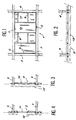
- FIGS. 1 to 4 is schematically represented, under the general reference 1, a conventional facade structure comprising a panel 2, mounted between vertical load-bearing walls such as 3 and 4 and horizontal support slabs, respectively 5 and 6, the assembly delimiting a cell with a rectangular profile in which the panel 2 is inserted directly.
- This is prefabricated in the factory and includes longitudinal members such as 8 and 9, vertical and horizontal, delimiting either solid panels 10 in which an appropriate lining is arranged, providing suitable sound and thermal insulation of the panel, or perforated parts 11 for the installation of a window for example.
- the panel 2 has a covering and protective cladding 12.
- Such prefabricated panels are difficult to manufacture due to their notable dimensions, even more so to transport and to put in place in the cells 7 intended to receive them. In addition, they practically do not make it possible to recover the possible games during assembly and also to play directly on the distribution, in the surface of the panel, of the longitudinal members 8 and 9 delimiting the panels 10 and the perforated parts 11.
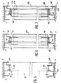
- the invention overcomes these drawbacks using a facade structure as shown in Figures 5 to 12.
- the parts 18 and 19 themselves have hooks 20 and 21, arranged to cooperate with the hooks 16 and 17 of the two rails, while allowing these parts to slide freely according to the length of the latter to come to be placed in any suitable position inside the cell 7 delimited between the slabs 5 and 6 (and the vertical bearing walls which connect these two slabs.
- a vertical profile 22 is assembled on the connecting pieces 18 and 19, constituted by a hollow metallic element, the cross section of which is determined so that the two connecting pieces engage at a sufficient depth in the ends of the profile, thus being arranged in the vertical extension of one another on the top and bottom horizontal rails 14 and 15.
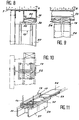
- FIGs 8 to 11 illustrate an alternative embodiment on which identical reference numerals have been used to designate members similar to those described in the example of Figures 5 to 7.
- each assembly part, here the part 19 mounted under the top rail 15 and suspended from the latter by its hooks 17, has two extensions, 27 and 28 respectively, neighbors but separate, to allow the mounting of two separate connecting sections, or even a single section, coming to fit as previously on the connecting pieces associated with the two rails.
- the part 19 represented thus comprises two tracks, respectively 30 and 31, in line with the extensions 27 and 28, with two opposite keys ensuring the blocking of the part following a sliding of these keys in the direction of one of the other with opposite movements.
- Figure 12 shows the facade structure in its final state of completion, the connecting profiles 22 mounted between the connecting pieces 18 and 19 on the beams 14 and 15, being associated towards the outside of the building with cladding or protective coating 32 and towards the inside of the cell 7 to lining panels 33 and 34, fixed and immobilized with respect to the sections by connecting irons 35 or 36 suitably distributed according to the height of these sections.
- a facade structure of very simple design is thus produced, and which allows all the adaptations which may be envisaged with the frames of doors, windows or the like, to be mounted in this facade, prior to the installation of the usual filling panels. between these frames and, if necessary, that of the exterior cladding.
- This structure is simple to manufacture, very easy to set up, in particular without requiring specialized labor and is therefore a particularly advantageous cost price.
Description
La présente invention est relative à une structure de façade pour immeuble ou construction analogue, telle que décrite, par exemple, dans GB-A-1 211 882 ou FR-A-1 395 895, notamment du type constitué de parois porteuses verticales, s'étendant selon la profondeur du bâtiment à partir de dalles horizontales délimitant les étages successifs de cet immeuble, ces parois et dalles formant ensemble des alvéoles dans lesquels se répartissent les logements ou pièces à prévoir dans le bâtiment, à chacun des niveaux de celui-ci.The present invention relates to a facade structure for a building or similar construction, as described, for example, in GB-A-1 211 882 or FR-A-1 395 895, in particular of the type consisting of vertical load-bearing walls, s extending according to the depth of the building from horizontal slabs delimiting the successive floors of this building, these walls and slabs together forming cells in which are distributed the dwellings or rooms to be provided in the building, at each level thereof .
Dans la partie de l'immeuble qui est disposé vers l'extérieur de celui-ci, les alvéoles ainsi délimités sont fermés par un mur de façade, dit mur "manteau", vertical, perpendiculaire aux dalles et aux parois porteuses précitées, ce mur comportant usuellement un panneau inséré dans l'ouverture de chaque alvéole et qui incorpore une structure de support pour des éléments d'isolation phonique, thermique et de protection vis-à-vis de l'eau, du vent et le cas échéant du feu.In the part of the building which is arranged towards the outside thereof, the cells thus delimited are closed by a front wall, said "mantle" wall, vertical, perpendicular to the aforementioned slabs and load-bearing walls, this wall usually comprising a panel inserted into the opening of each cell and which incorporates a support structure for elements of sound, thermal insulation and protection against water, wind and, where appropriate, fire.
Sur ce panneau est ensuite rapporté un garnissage extérieur ou bardage, généralement en pierres, en briques ou autres, formant la façage externe du bâtiment.This panel is then fitted with an exterior covering or cladding, generally made of stones, bricks or the like, forming the external facade of the building.
Cette pratique habituelle exige toutefois, pour la réalisation d'immeubles collectifs où la structure de la façade est généralement répétitive selon la hauteur et la longueur du bâtiment, que les panneaux rapportés entre parois porteuses verticales et dalles horizontales, soient fabriqués en usine, avec un positionnement précis de chaque panneau et des châssis de portes ou fenêtres qu'il comporte, entre lesquels est ensuite mise en place et immobilisée la garniture d'isolation prévue.This usual practice requires however, for the realization of collective buildings where the structure of the facade is generally repetitive according to the height and the length of the building, that the panels reported between vertical load-bearing walls and horizontal slabs, must be manufactured in the factory, with a precise positioning of each panel and of the door or window frames it contains, between which the intended insulation lining is then put in place and immobilized.
Ces solutions sont lourdes et relativement onéreuses, chaque panneau ainsi préfabriqué, dont les dimensions peuvent être notables, devant être transporté et mis en place en une seule opération, les emplacements des châssis dans chaque panneau étant immuables. Il peut alors en résulter des difficultés pour rattraper les jeux inévitables d'un panneau à l'autre, afin de conférer à l'ensemble un aspect régulier et exactement répétitiF.These solutions are heavy and relatively expensive, each panel thus prefabricated, the dimensions of which can be significant, having to be transported and put in place in a single operation, the locations of the frames in each panel being immutable. This can then cause difficulties in catching up on the inevitable clearances from one panel to another, in order to give the whole a regular and exactly repetitive appearance.
La présente invention concerne une structure de façade d'une conception entièrement différente, permettant de disposer et de répartir, directement sur place, les châssis des portes et fenêtres à l'intérieur du panneau, en particulier en autorisant tous les ajustements éventuels qui peuvent se révéler nécessaires avant d'être immobilisés et de monter entre ces châssis la garniture d'isolation et d'étanchéité indispensable, et enfin de rapporter en dernier lieu le bardage extérieur de finition et de protection.The present invention relates to a facade structure of an entirely different design, making it possible to arrange and distribute, directly on site, the door frames and windows inside the panel, in particular by authorizing any adjustments that may prove necessary before being immobilized and mounting between these frames the essential insulation and sealing gasket, and finally bringing back last exterior cladding for finishing and protection.
A cet effet, la structure considérée, à monter entre deux parois verticales porteuses et deux dalles horizontales séparées par ces parois, en délimitant ensemble un alvéole ouvert vers l'extérieur en façade d'un immeuble, se caractérise en ce qu'elle comporte, disposée au voisinage du bord extérieur ou nez des dalles, deux lisses parallèles au plan de la façade extérieure fermant l'alvéole, ces lisses, respectivement haute et basse, étant horizontales et fixées en regard sur le dessus de la dalle inférieure et sur le dessous de la dalle supérieure, chaque lisse présentant des crochets de suspension pour la lisse haute et de guidage et de maintien pour la lisse basse, d'au moins une pièce d'assemblage comportant également des crochets coopérant avec ceux des lisses, et au moins un profilé vertical plein ou creux, ouvert à ses extrémités dans lesquelles s'engagent les pièces d'assemblage portées par les lisses haute et basse, des clavettes de blocage étant prévues pour s'engager transversalement entre chaque lisse et la pièce d'assemblage coopérant avec elle, entre la face inférieure de la lisse et la face supérieure de la pièce, chaque clavette comportant un profil incliné sur l'horizontale, de telle sorte que son déplacement transversal entre la lisse et la pièce les immobilise mutuellement en position en même temps que le profilé vertical correspondant.To this end, the structure considered, to be mounted between two vertical load-bearing walls and two horizontal slabs separated by these walls, by delimiting together a cell open towards the outside in front of a building, is characterized in that it comprises, arranged in the vicinity of the outer edge or nose of the slabs, two healds parallel to the plane of the external facade closing the cell, these healds, respectively high and low, being horizontal and fixed opposite on the top of the lower slab and on the bottom of the upper slab, each stringer having suspension hooks for the high stringer and for guiding and holding for the low stringer, at least one assembly part also comprising hooks cooperating with those of the struts, and at least one solid or hollow vertical profile, open at its ends in which the connecting parts carried by the top and bottom rails are engaged, locking keys being provided for engaging transversely between each stringer and the connecting part cooperating with it, between the underside of the stringer and the upper face of the part, each key having a profile inclined to the horizontal, so that its transverse movement between the arm and the part immobilizes them mutually in position at the same time as the corresponding vertical profile.
La structure selon l'invention consiste ainsi à munir les surfaces en regard de deux dalles horizontales entre deux parois porteuses verticales, de deux lisses parallèles, faisant fonction de rails de guidage pour des pièces d'assemblage, se crochetant respectivement dans ces lisses, en permettant leur déplacement selon la dimension longitudinale de ces dernières pour ajuster leur positionnement conformément à la structure du panneau de façade souhaitée.The structure according to the invention thus consists in providing the facing surfaces with two horizontal slabs between two vertical load-bearing walls, with two parallel rails, acting as guide rails for assembly parts, hooking respectively in these rails, allowing their displacement along the longitudinal dimension of the latter to adjust their positioning in accordance with the structure of the desired facade panel.
Chaque paire de pièces d'assemblage ainsi portée par la lisse haute et par la lisse basse, est associée à un profilé vertical de liaison dans les extrémités ouvertes duquel s'engagent les pièces, ce profilé assurant ainsi, dans le sens vertical la continuité du châssis formé avec les lisses.Each pair of assembly parts thus carried by the top rail and by the bottom rail, is associated with a vertical connecting profile in the open ends of which the parts engage, this profile thus ensuring, in the vertical direction the continuity of the frame formed with the beams.
Lorsque le profilé ainsi assemblé avec les deux pièces est amené dans sa position désirée, selon la longueur des lisses, les clavettes de blocage permettent de l'immobiliser définitivement dans celle-ci, le panneau de façade étant ensuite achevé par mise en place entre les châssis successifs ainsi formés d'un remplissage ou garniture puis du bardage extérieur final.When the profile thus assembled with the two parts is brought into its desired position, along the length of the beams, the locking keys allow it to be immobilized definitively therein, the front panel then being completed by positioning between the successive frames thus formed of a filling or lining then of the final exterior cladding.
Selon un mode de réalisation préféré, chaque profilé vertical comporte, en partie courante, entre les pièces d'assemblage engagées dans ses extrémités, un ou plusieurs fers en omega ou autre, permettant l'accrochage sur ce profilé du bardage extérieur ou de panneaux d'isolation.According to a preferred embodiment, each vertical profile comprises, in the running part, between the assembly pieces engaged at its ends, one or more irons made of omega or other, allowing the hanging on this profile of the exterior cladding or of panels of 'insulation.
Avantageusement, le bardage extérieur peut comporter une garniture de renfort seulement, améliorant la protection thermique et/ou acoustique de la structure.Advantageously, the exterior cladding may comprise a reinforcing lining only, improving the thermal and / or acoustic protection of the structure.
Selon une autre caractéristique également, chaque pièce d'assemblage comporte une face supérieure présentant au moins une surface en pente inclinée sur l'horizontale, la clavette de blocage qui coulisse entre la lisse et la pièce épousant la forme d'un coin avec une face inclinée présentant la même pente, afin de provoquer en fin de course le blocage complet de la lisse et de la pièce.According to another characteristic also, each assembly part has an upper face having at least one sloping surface inclined to the horizontal, the locking key which slides between the heald and the part taking the shape of a corner with one face. inclined with the same slope, in order to cause the complete blocking of the arm and the part at the end of the race.
En variante préférée, chaque pièce d'assemblage peut comporter un ou plusieurs prolongements parallèles pour l'engagement de deux profilés verticaux voisins, et présentent, au droit de chacun de ces prolongements, des surfaces inclinées, prévues de part et d'autre de la pièce et ayant des pentes opposées, de manière à coopérer avec deux clavettes distinctes coulissant l'une en direction de l'autre.In a preferred variant, each assembly part may comprise one or more parallel extensions for the engagement of two neighboring vertical sections, and have, at the right of each of these extensions, inclined surfaces, provided on either side of the part and having opposite slopes, so as to cooperate with two separate keys sliding one towards the other.
D'autres caractéristiques d'une structure de façade pour immeuble ou bâtiment analogue, établie conformément à l'invention, apparaîtront encore à travers la description qui suit de divers exemples de réalisation, donnés à titre indicatif et non limitatif, en référence aux dessins annexés, sur lesquels
- Les Figures 1 à 4 sont des vues de face en élévation, de dessus, et de côté selon deux plans de coupe verticaux parallèles d'une façade classique.
- Les Figures 5, 6 et 7 sont des vues en coupe verticale partielle, à plus grande échelle, de la structure selon l'invention, permettant de préciser les différentes étapes de l'élaboration et du montage de celle-ci.
- Les Figures 8, 9 et 10 sont des vues de détail d'une variante de réalisation préférée de la lisse supérieure, de la pièce d'assemblage et de la clavette de blocage, de la structure considérée.
- La Figure 11 est une vue en perspective de la pièce d'assemblage selon les Figures de la variante précédente, et d'une des clavettes de blocage associée à cette pièce.
- La Figure 12 représente la structure dans son état d'achèvement final, avec un bardage extérieur et des panneaux d'isolation.
- Figures 1 to 4 are front elevation, top, and side views along two parallel vertical section planes of a conventional facade.
- Figures 5, 6 and 7 are views in partial vertical section, on a larger scale, of the structure according to the invention, making it possible to specify the different stages of the development and assembly thereof.
- Figures 8, 9 and 10 are detailed views of a preferred alternative embodiment of the top rail, the connecting piece and the locking key, of the structure considered.
- Figure 11 is a perspective view of the assembly part according to the Figures of the previous variant, and one of the locking keys associated with this part.
- Figure 12 shows the structure in its final state of completion, with external cladding and insulation panels.
Sur les Figures 1 à 4, est schématiquement représentée, sous la référence générale 1, une structure de façade classique comportant un panneau 2, monté entre des parois porteuses verticales telles que 3 et 4 et des dalles horizontales de support, respectivement 5 et 6, l'ensemble délimitant un alvéole à profil rectangulaire dans lequel s'insère directement le panneau 2.In FIGS. 1 to 4, is schematically represented, under the general reference 1, a conventional facade structure comprising a
Celui-ci est préfabriqué en usine et comporte des longerons tels que 8 et 9, verticaux et horizontaux, délimitant soit des panneaux pleins 10 dans lesquels est disposé un garnissage approprié, procurant une isolation phonique et thermique convenable du panneau, soit des parties ajourées 11 pour la mise en place d'une fenêtre par exemple.This is prefabricated in the factory and includes longitudinal members such as 8 and 9, vertical and horizontal, delimiting either
Extérieurement, le panneau 2 comporte un bardage de revêtement et de protection 12.Externally, the
De tels panneaux préfabriqués sont difficiles à fabriquer en raison de leurs dimensions notables, plus encore à transporter et à mettre en place dans les alvéoles 7 destinés à les recevoir. En outre, ils ne permettent pratiquement pas de récupérer les jeux éventuels au montage et également de jouer de façon directe sur la répartition, dans la surface du panneau, des longerons 8 et 9 délimitant les panneaux 10 et les parties ajourées 11.Such prefabricated panels are difficult to manufacture due to their notable dimensions, even more so to transport and to put in place in the
L'invention permet de pallier ces inconvénients à l'aide d'une structure de façade telle que représentée sur les Figures 5 à 12.The invention overcomes these drawbacks using a facade structure as shown in Figures 5 to 12.
Sur la Figure 5, on retrouve les dalles inférieure 5 et supérieure 6, délimitant l'alvéole 7 prévu pour recevoir le panneau 2, comme dans l'état de la technique antérieur tel que rappelé ci-dessus. Toutefois, dans ce cas, on fixe par des moyens d'ancrage schématiquement représentés en 13, respectivement sur le dessus de la dalle horizontale 5, et le dessous de la dalle 6, des lisses basse 14 et haute 15, constituées l'une et l'autre de profilés métalliques, formant des rails et comportant notamment, pour la lisse basse des crochets de guidage 16 et pour la lisse haute des crochets de support 17.In FIG. 5, we find the lower 5 and upper 6 slabs, delimiting the
Une fois les lisses ainsi mises en place, on rapporte sur ces dernières, deux pièces d'assemblage, désignées par les références 18 pour celle associée à la lisse basse 14, 19 pour celle suspendue sous la lisse haute 15.Once the healds thus put in place, two assembly parts are reported on the latter, designated by the
A cet effet et comme représenté sur la Figure 6, les pièces 18 et 19 comportent elles-mêmes des crochets 20 et 21, aménagés pour venir coopérer avec les crochets 16 et 17 des deux lisses, tout en permettant à ces pièces de coulisser librement selon la longueur de ces dernières pour venir se disposer dans une position quelconque appropriée à l'intérieur de l'alvéole 7 délimité entre les dalles 5 et 6 (et les parois porteuses verticales qui relient ces deux dalles.To this end and as shown in Figure 6, the
Simultanément, on monte sur les pièces d'assemblage 18 et 19 un profilé vertical 22, constitué par un élément métallique creux, dont la section est déterminée de telle sorte que les deux pièces d'assemblage s'engagent sur une profondeur suffisante dans les extrémités du profilé, en étant ainsi disposées dans le prolongement vertical l'une de l'autre sur les lisses horizontales haute et basse 14 et 15.Simultaneously, a
Dans une troisième étape du montage illustrée sur la Figure 7, on bloque en place les lisses 14 et 15 vis-à-vis des pièces 18 et 19 et par suite du profilé 22 qui les relie au moyen de deux clavettes, respectivement 23 et 24, engagées à force entre une portée d'appui 25 de la lisse correspondante et la surface en regard 26 de l'une et l'autre des deux pièces.In a third stage of assembly illustrated in Figure 7, we block in place the
On conçoit ainsi que l'on peut, de la manière la plus simple, aménager l'alvéole 7, en répartissant dans celui-ci les profilés de liaison verticaux 22, de telle sorte que ceux-ci occupent des positions précises et exactement ajustées.It is thus understood that it is possible, in the simplest way, to arrange the
Les Figures 8 à 11 illustrent une variante de réalisation sur laquelle on a repris des chiffres de référence identiques pour désigner des organes semblables à ceux décrits dans l'exemple des Figures 5 à 7.Figures 8 to 11 illustrate an alternative embodiment on which identical reference numerals have been used to designate members similar to those described in the example of Figures 5 to 7.
Dans ce cas et comme on le voit plus particulièrement sur la vue en perspective de la Figure 11, chaque pièce d'assemblage, ici la pièce 19 montée sous la lisse haute 15 et suspendue à cette dernière par ses crochets 17, comporte deux prolongements, respectivement 27 et 28, voisins mais séparés, pour permettre le montage de deux profilés de liaison distincts, voire d'un profilé unique, venant s'emboîter comme précédemment sur les pièces de liaison associées aux deux lisses.In this case and as can be seen more particularly in the perspective view of FIG. 11, each assembly part, here the
Dans cette variante toutefois, on utilise deux clavettes 24 dont une seule est représentée sur la Figure 11, ces clavettes comportant une face inférieure inclinée 29 apte à coopérer avec une piste 30 de même profil prévue dans la pièce de liaison. Dans cette réalisation, la pièce 19 représentée comporte ainsi deux pistes, respectivement 30 et 31, au droit des prolongements 27 et 28, avec deux clavettes opposées assurant le blocage de la pièce consécutivement à un coulissement de ces clavettes en direction l'une de l'autre avec des mouvements opposés.In this variant, however, two
La Figure 12 montre la structure de façade dans son état d'achèvement final, les profilés de liaison 22 montés entre les pièces de liaison 18 et 19 surles lisses 14 et 15, étant associés vers l'extérieur du bâtiment un bardage ou revêtement de protection 32 et vers l'intérieur de l'alvéole 7 à des panneaux de garnissage 33 et 34, fixés et immobilisés vis-à-vis des profilés par des fers de liaison 35 ou 36 convenablement répartis selon la hauteur de ces profilés.Figure 12 shows the facade structure in its final state of completion, the connecting
On réalise ainsi une structure de façade de conception très simple, et qui permet toutes les adaptations susceptibles d'être envisagées avec les châssis de portes, fenêtres ou autres, à monter dans cette façade, préalablement à la mise en place des panneaux de remplissage usuels entre ces châssis et le cas échéant à celle du bardage extérieur.A facade structure of very simple design is thus produced, and which allows all the adaptations which may be envisaged with the frames of doors, windows or the like, to be mounted in this facade, prior to the installation of the usual filling panels. between these frames and, if necessary, that of the exterior cladding.
Cette structure est simple à fabriquer, très facile à mettre en place, notamment sans exiger une main-d'oeuvre spécialisée et est par suite d'un prix de revient particulièrement avantageux.This structure is simple to manufacture, very easy to set up, in particular without requiring specialized labor and is therefore a particularly advantageous cost price.
Bien entendu, il va de soi que l'invention ne se limite pas aux exemples plus spécialement décrits ci-dessus, en référence aux dessins annexés ; elle en embrasse au contraire toutes les variantes, telles que décrites dans les revendications.Of course, it goes without saying that the invention is not limited to the examples more particularly described above, with reference to the accompanying drawings; on the contrary, it embraces all variants thereof, as described in the claims.
Claims (5)
- Façade structure for a building or similar construction, to be erected between two vertical bearing walls and two horizontal slabs (5, 6) separated by these walls, together delimiting a cell (7) open towards the outside as the façade of a building, the said structure including, located close to the outer edge or tip of the slabs, two rails (14, 15) parallel to the plane of the outer façade closing the cell, these rails, respectively a top rail (15) and a bottom rail (14) being horizontal and fixed facing each other on the top of the lower slab and on the underside of the upper slab, each rail having hooks, in the case of the top rail a hook (17) for hanging and, in the case of the bottom rail, a hook (16) for guiding and holding at least one assembly piece (18, 19) also including hooks (20, 21) interacting with those of the rails, and at least one solid or hollow vertical section piece (22) open at its ends in which the assembly pieces borne by the top and bottom rails engage, locking keys (23, 24) being provided to engage transversely between each rail and the assembly piece interacting with it, between the lower face (25) of the rail and the upper face (26) of the piece, each key including a profile which is inclined to the horizontal, so that its transverse displacement between the rail and the piece immobilizes them mutually in position at the same time as the corresponding vertical section piece.
- Façade structure according to claim 1, characterized in that each vertical section piece (22) includes, along its span, between the assembly pieces (18, 19) engaged in its ends, one or more omega brackets or brackets of some other shape (35, 36), allowing the external cladding (32) or insulation panels (33) to be fastened to this section piece.
- Façade structure according to Claim 2, characterized in that the external cladding may include just a reinforcing lining improving thermal and/or acoustic protection.
- Façade structure according to any one of Claims 1 to 3, characterized in that each assembly piece (18, 19) includes an upper face exhibiting at least one sloped surface inclined to the horizontal, the locking key (23, 24) which slides between the rail and the piece adopting the shape of a wedge with an inclined face exhibiting the same slope.
- Façade structure according to any one of Claims 1 to 4, characterized in that each assembly piece (18, 19) includes one or more parallel extensions (27, 28) for the engagement of two neighbouring vertical section pieces and exhibit, in line with each of these extensions, inclined surfaces (30, 31) provided on either side of the piece and having opposite slopes, so as to interact with two distinct keys sliding towards each other.
Applications Claiming Priority (2)
| Application Number | Priority Date | Filing Date | Title |
|---|---|---|---|
| FR9413920A FR2727142B1 (en) | 1994-11-21 | 1994-11-21 | FACADE STRUCTURE FOR BUILDING OR THE LIKE |
| FR9413920 | 1994-11-21 |
Publications (2)
| Publication Number | Publication Date |
|---|---|
| EP0712970A1 EP0712970A1 (en) | 1996-05-22 |
| EP0712970B1 true EP0712970B1 (en) | 1997-09-03 |
Family
ID=9469000
Family Applications (1)
| Application Number | Title | Priority Date | Filing Date |
|---|---|---|---|
| EP19950402465 Expired - Lifetime EP0712970B1 (en) | 1994-11-21 | 1995-11-03 | Façade structure for buildings or similar constructions |
Country Status (6)
| Country | Link |
|---|---|
| EP (1) | EP0712970B1 (en) |
| DE (1) | DE69500653T2 (en) |
| ES (1) | ES2109067T3 (en) |
| FR (1) | FR2727142B1 (en) |
| GR (1) | GR3025108T3 (en) |
| MA (1) | MA23721A1 (en) |
Families Citing this family (2)
| Publication number | Priority date | Publication date | Assignee | Title |
|---|---|---|---|---|
| GR1002827B (en) * | 1996-10-16 | 1997-12-19 | Glass walls with suspended glass holders. | |
| FR2760031B1 (en) * | 1997-02-21 | 1999-05-14 | Alcan France | DEVICE FOR LAYING AND SUPPORTING A SEALING FILM IN A FRONT STRUCTURE FOR A BUILDING OR THE LIKE |
Family Cites Families (3)
| Publication number | Priority date | Publication date | Assignee | Title |
|---|---|---|---|---|
| FR1395895A (en) * | 1963-04-09 | 1965-04-16 | Prefabricated panel used to form a building wall | |
| GB1211882A (en) * | 1967-01-25 | 1970-11-11 | Astralite Ltd | Improvements in or relating to building constructions |
| FR1540506A (en) * | 1967-08-18 | 1968-09-27 | Boussois Souchon Neuvesel Sa | Process for the erection of building facades and related prefabricated panels |
-
1994
- 1994-11-21 FR FR9413920A patent/FR2727142B1/en not_active Expired - Fee Related
-
1995
- 1995-11-03 DE DE1995600653 patent/DE69500653T2/en not_active Expired - Fee Related
- 1995-11-03 EP EP19950402465 patent/EP0712970B1/en not_active Expired - Lifetime
- 1995-11-03 ES ES95402465T patent/ES2109067T3/en not_active Expired - Lifetime
- 1995-11-16 MA MA24068A patent/MA23721A1/en unknown
-
1997
- 1997-10-21 GR GR970402750T patent/GR3025108T3/en unknown
Also Published As
| Publication number | Publication date |
|---|---|
| FR2727142B1 (en) | 1997-01-31 |
| DE69500653T2 (en) | 1998-01-29 |
| MA23721A1 (en) | 1996-07-01 |
| EP0712970A1 (en) | 1996-05-22 |
| DE69500653D1 (en) | 1997-10-09 |
| FR2727142A1 (en) | 1996-05-24 |
| ES2109067T3 (en) | 1998-01-01 |
| GR3025108T3 (en) | 1998-01-30 |
Similar Documents
| Publication | Publication Date | Title |
|---|---|---|
| EP1741872B1 (en) | Roller shutter system | |
| FR2948718A1 (en) | Joinery structure for opening in building, has collection system collecting force from structure, and comprising upper part contacted and connected with inner face of lintel and lower part contacted and connected with wall of casing element | |
| FR2540160A1 (en) | Device for fastening prefabricated facade panels onto the structure of a building | |
| EP0712970B1 (en) | Façade structure for buildings or similar constructions | |
| WO2001088293A1 (en) | Building framework | |
| FR2743588A1 (en) | STRUCTURAL SYSTEM FOR THE CONSTRUCTION OF BUILDINGS, PARTICULARLY SINGLE-FAMILY HOMES | |
| EP0373079A1 (en) | Building with a modular structure | |
| FR2545143A1 (en) | Glass partitions for bays of large surface area | |
| FR2624153A1 (en) | SUPPORT STRUCTURE FOR ADDITIONAL CONSTRUCTIONS, ESPECIALLY OF THE GENRE VERANDAS OR THE LIKE | |
| EP0091894A1 (en) | Girder-support gutter for a roof | |
| FR2515231A1 (en) | ||
| FR2558875A1 (en) | System for lining walls or facades of buildings, elements of such a system and method for implementing this system | |
| EP3067479A1 (en) | Modular construction with prefabricated elements | |
| FR2614054A1 (en) | Method for constructing walls of buildings | |
| FR2681357A1 (en) | Prefabricated panel with concrete facing, method for manufacturing it and building module formed of such panels | |
| FR2567841A1 (en) | PLATFORM CONSTRUCTION SYSTEM COMPRISING PREFABRICATED WALL AND ROOF PANELS FOR VESSELS AND SIMILAR BODIES | |
| FR2533959A1 (en) | Slip-on cladding device. | |
| FR2579648A1 (en) | Device for fixing and assembling timber framework elements for producing ceilings, particularly those in the so-called French style, and also support posts and other similar assemblies | |
| FR2581410A1 (en) | Novel facing or cladding panels | |
| FR2573110A1 (en) | Method for constructing a building having a light framework with external facing, brick intended for this facing, wall and framework constructed according to this method | |
| FR2599408A1 (en) | Self-supporting panel or module, device for assemling such modules and structure for producing a construction such as a building comprising such modules. | |
| FR2718172A1 (en) | Sandwich load-bearing wall panel, profile for such a panel, construction comprising such panels. | |
| FR3118078A1 (en) | Device and method for edge-to-edge fastening of two panels together | |
| FR2523176A1 (en) | METHOD FOR BUILDING A BUILDING, AND PANELS FOR CARRYING OUT SAID METHOD | |
| FR2796666A1 (en) | Veranda-type structure has roller blind housings at top of wall sections |
Legal Events
| Date | Code | Title | Description |
|---|---|---|---|
| PUAI | Public reference made under article 153(3) epc to a published international application that has entered the european phase |
Free format text: ORIGINAL CODE: 0009012 |
|
| AK | Designated contracting states |
Kind code of ref document: A1 Designated state(s): BE CH DE ES GB GR IE IT LI LU NL PT |
|
| 17P | Request for examination filed |
Effective date: 19960603 |
|
| GRAG | Despatch of communication of intention to grant |
Free format text: ORIGINAL CODE: EPIDOS AGRA |
|
| GRAH | Despatch of communication of intention to grant a patent |
Free format text: ORIGINAL CODE: EPIDOS IGRA |
|
| 17Q | First examination report despatched |
Effective date: 19970206 |
|
| GRAH | Despatch of communication of intention to grant a patent |
Free format text: ORIGINAL CODE: EPIDOS IGRA |
|
| GRAA | (expected) grant |
Free format text: ORIGINAL CODE: 0009210 |
|
| AK | Designated contracting states |
Kind code of ref document: B1 Designated state(s): BE CH DE ES GB GR IE IT LI LU NL PT |
|
| REG | Reference to a national code |
Ref country code: CH Ref legal event code: EP |
|
| REF | Corresponds to: |
Ref document number: 69500653 Country of ref document: DE Date of ref document: 19971009 |
|
| ITF | It: translation for a ep patent filed |
Owner name: INTERPATENT ST.TECN. BREV. |
|
| GBT | Gb: translation of ep patent filed (gb section 77(6)(a)/1977) |
Effective date: 19971021 |
|
| REG | Reference to a national code |
Ref country code: CH Ref legal event code: NV Representative=s name: PATENTANWAELTE SCHAAD, BALASS, MENZL & PARTNER AG |
|
| REG | Reference to a national code |
Ref country code: GR Ref legal event code: FG4A Free format text: 3025108 |
|
| REG | Reference to a national code |
Ref country code: ES Ref legal event code: FG2A Ref document number: 2109067 Country of ref document: ES Kind code of ref document: T3 |
|
| REG | Reference to a national code |
Ref country code: IE Ref legal event code: FG4D Free format text: 76263 |
|
| REG | Reference to a national code |
Ref country code: PT Ref legal event code: SC4A Free format text: AVAILABILITY OF NATIONAL TRANSLATION Effective date: 19971113 |
|
| PLBE | No opposition filed within time limit |
Free format text: ORIGINAL CODE: 0009261 |
|
| STAA | Information on the status of an ep patent application or granted ep patent |
Free format text: STATUS: NO OPPOSITION FILED WITHIN TIME LIMIT |
|
| 26N | No opposition filed | ||
| REG | Reference to a national code |
Ref country code: GB Ref legal event code: 732E |
|
| REG | Reference to a national code |
Ref country code: CH Ref legal event code: PFA Free format text: ALCAN FRANCE TRANSFER- TECHNAL Ref country code: CH Ref legal event code: NV Representative=s name: KATZAROV S.A. |
|
| REG | Reference to a national code |
Ref country code: GB Ref legal event code: IF02 |
|
| PGFP | Annual fee paid to national office [announced via postgrant information from national office to epo] |
Ref country code: PT Payment date: 20020809 Year of fee payment: 8 |
|
| PGFP | Annual fee paid to national office [announced via postgrant information from national office to epo] |
Ref country code: GR Payment date: 20020823 Year of fee payment: 8 |
|
| PGFP | Annual fee paid to national office [announced via postgrant information from national office to epo] |
Ref country code: BE Payment date: 20020830 Year of fee payment: 8 |
|
| PGFP | Annual fee paid to national office [announced via postgrant information from national office to epo] |
Ref country code: ES Payment date: 20020902 Year of fee payment: 8 |
|
| PGFP | Annual fee paid to national office [announced via postgrant information from national office to epo] |
Ref country code: GB Payment date: 20021030 Year of fee payment: 8 |
|
| PGFP | Annual fee paid to national office [announced via postgrant information from national office to epo] |
Ref country code: IE Payment date: 20021120 Year of fee payment: 8 |
|
| PGFP | Annual fee paid to national office [announced via postgrant information from national office to epo] |
Ref country code: NL Payment date: 20021121 Year of fee payment: 8 Ref country code: LU Payment date: 20021121 Year of fee payment: 8 |
|
| PGFP | Annual fee paid to national office [announced via postgrant information from national office to epo] |
Ref country code: DE Payment date: 20021213 Year of fee payment: 8 |
|
| PGFP | Annual fee paid to national office [announced via postgrant information from national office to epo] |
Ref country code: CH Payment date: 20030203 Year of fee payment: 8 |
|
| PG25 | Lapsed in a contracting state [announced via postgrant information from national office to epo] |
Ref country code: LU Free format text: LAPSE BECAUSE OF NON-PAYMENT OF DUE FEES Effective date: 20031103 Ref country code: IE Free format text: LAPSE BECAUSE OF NON-PAYMENT OF DUE FEES Effective date: 20031103 Ref country code: GB Free format text: LAPSE BECAUSE OF NON-PAYMENT OF DUE FEES Effective date: 20031103 |
|
| PG25 | Lapsed in a contracting state [announced via postgrant information from national office to epo] |
Ref country code: ES Free format text: LAPSE BECAUSE OF NON-PAYMENT OF DUE FEES Effective date: 20031104 |
|
| PG25 | Lapsed in a contracting state [announced via postgrant information from national office to epo] |
Ref country code: LI Free format text: LAPSE BECAUSE OF NON-PAYMENT OF DUE FEES Effective date: 20031130 Ref country code: CH Free format text: LAPSE BECAUSE OF NON-PAYMENT OF DUE FEES Effective date: 20031130 Ref country code: BE Free format text: LAPSE BECAUSE OF NON-PAYMENT OF DUE FEES Effective date: 20031130 |
|
| BERE | Be: lapsed |
Owner name: *ALCAN FRANCE Effective date: 20031130 |
|
| PG25 | Lapsed in a contracting state [announced via postgrant information from national office to epo] |
Ref country code: PT Free format text: LAPSE BECAUSE OF NON-PAYMENT OF DUE FEES Effective date: 20040531 |
|
| PG25 | Lapsed in a contracting state [announced via postgrant information from national office to epo] |
Ref country code: NL Free format text: LAPSE BECAUSE OF NON-PAYMENT OF DUE FEES Effective date: 20040601 |
|
| PG25 | Lapsed in a contracting state [announced via postgrant information from national office to epo] |
Ref country code: DE Free format text: LAPSE BECAUSE OF NON-PAYMENT OF DUE FEES Effective date: 20040602 |
|
| PG25 | Lapsed in a contracting state [announced via postgrant information from national office to epo] |
Ref country code: GR Free format text: LAPSE BECAUSE OF NON-PAYMENT OF DUE FEES Effective date: 20040603 |
|
| GBPC | Gb: european patent ceased through non-payment of renewal fee |
Effective date: 20031103 |
|
| REG | Reference to a national code |
Ref country code: CH Ref legal event code: PL |
|
| NLV4 | Nl: lapsed or anulled due to non-payment of the annual fee |
Effective date: 20040601 |
|
| REG | Reference to a national code |
Ref country code: IE Ref legal event code: MM4A |
|
| REG | Reference to a national code |
Ref country code: PT Ref legal event code: MM4A Free format text: LAPSE DUE TO NON-PAYMENT OF FEES Effective date: 20040531 |
|
| REG | Reference to a national code |
Ref country code: ES Ref legal event code: FD2A Effective date: 20031104 |
|
| PG25 | Lapsed in a contracting state [announced via postgrant information from national office to epo] |
Ref country code: IT Free format text: LAPSE BECAUSE OF NON-PAYMENT OF DUE FEES;WARNING: LAPSES OF ITALIAN PATENTS WITH EFFECTIVE DATE BEFORE 2007 MAY HAVE OCCURRED AT ANY TIME BEFORE 2007. THE CORRECT EFFECTIVE DATE MAY BE DIFFERENT FROM THE ONE RECORDED. Effective date: 20051103 |