EP0094859B1 - Test button for a differential trip device - Google Patents
Test button for a differential trip device Download PDFInfo
- Publication number
- EP0094859B1 EP0094859B1 EP19830400874 EP83400874A EP0094859B1 EP 0094859 B1 EP0094859 B1 EP 0094859B1 EP 19830400874 EP19830400874 EP 19830400874 EP 83400874 A EP83400874 A EP 83400874A EP 0094859 B1 EP0094859 B1 EP 0094859B1
- Authority
- EP
- European Patent Office
- Prior art keywords
- button
- push button
- hole
- spring blade
- push
- Prior art date
- Legal status (The legal status is an assumption and is not a legal conclusion. Google has not performed a legal analysis and makes no representation as to the accuracy of the status listed.)
- Expired
Links
Images
Classifications
-
- H—ELECTRICITY
- H01—ELECTRIC ELEMENTS
- H01H—ELECTRIC SWITCHES; RELAYS; SELECTORS; EMERGENCY PROTECTIVE DEVICES
- H01H83/00—Protective switches, e.g. circuit-breaking switches, or protective relays operated by abnormal electrical conditions otherwise than solely by excess current
- H01H83/02—Protective switches, e.g. circuit-breaking switches, or protective relays operated by abnormal electrical conditions otherwise than solely by excess current operated by earth fault currents
- H01H83/04—Protective switches, e.g. circuit-breaking switches, or protective relays operated by abnormal electrical conditions otherwise than solely by excess current operated by earth fault currents with testing means for indicating the ability of the switch or relay to function properly
- H01H2083/045—Auxiliary switch opening testing circuit in synchronism with the main circuit
Definitions
- the invention relates to a differential tripping device according to the preamble of claim 1.
- a triggering device of the kind mentioned, for example described in French patent No. S 2437692 or 2241868, comprises a test circuit actuated by the depressing of a push button. By pressing the push button, a bypass is closed comprising a control resistor which bypasses the differential current transformer and simulates a differential fault.
- Safety means limit the duration of closure of the switch to avoid destruction of the resistance.
- Known devices can be the cause of untimely tripping, in particular during an untimely closing, for example due to priming between the contacts of the switch of the test circuit.
- the object of the present invention is to remedy this drawback by implementing the features mentioned in claim 1.
- the elastic blade By retracting the elastic blade constituting the movable contact inside the push-button of insulating material, the risks of priming between the contacts of the test switch are substantially reduced or / and practically excluded.
- the elastic blade extends longitudinally inside an elongated recess formed in the push button, being interposed between a fixed stop and the bottom of the recess so that the pushing of the push button, resulting by bringing the bottom of the recess and the stop closer together, this causes the elastic blade to be deformed and protrudes from the free end of this blade.
- This free end is advantageously curved to facilitate deformation and exit through a slot in the push button in the vicinity of the bottom of the recess.
- the elastic blade can be arranged as a return spring or be associated with a return spring housed inside the recess of the push button.
- test button is described below in its application to a differential trigger block according to French patent N ° 2437692, which will advantageously be referred to for further details, and it suffices to recall that the differential block comprises a test button constituted by a button, the pressing of which simulates a differential fault by inserting an electrical resistance in a manner well known to specialists.
- the test button carries a movable contact 12 coming into contact, in the depressed position of the push button 10, of a semi-fixed contact 14 formed by the end of a spiral spring 16 in support of a movable stop 18.
- the end accompanies the stop 18 in its movement and the assembly is arranged in such a way that the contacts 12, 14 can only be closed on the double condition of pressing the push-button 10 and pivoting it.
- the stop 18 in an extreme position corresponding to the closing of the circuit breaker coupled to the differential unit.
- the contact 14 disappears as soon as the circuit breaker opens to limit the duration of supply of the shunt resistor.
- the push button 10 has in its lower part a longitudinal recess 20 open at its base 22.
- the push button 10 is slidably mounted in abutment on one face 24 of the mechanism housing and the recess 20 is open on the side of the face 24, but it is clear that the recess 20 can be completely closed on all sides.
- the recess 20 communicates with a slot 26 formed on the face of the push-button 10 opposite the contact 14 in the vicinity of the bottom 28 of the recess 20.
- the slot 26 is confined by a guide spout 30 whose function will emerge from the description below.
- the movable contact actuated by the push button 10 is constituted by an elastic blade 32 extending longitudinally inside the recess 20 while being fixed at its base by a folded part 34 to a fixed support 36 of the housing.
- the opposite end 38 of the elastic blade 32 is curved along the spout 30 to enter the slot 26.
- a spiral return spring 40 is interposed between the spout 30 and the fixed stop 36 to urge the push button 10 in rest and open position of the test switch.
- the assembly is arranged in such a way that in the open position of the test switch, the end 38 of the blade 32 constituting the movable contact of the switch is retracted inside the recess 20, preventing any risk of priming between contacts 14, 38.
- Fig. 2 shows the switch in the closed position and it can be seen that when the push-button 10 is pressed the elastic blade 32 in support of the bottom 28 is folded back to project the end 38 which comes into contact with the contact 14 The deformation of the elastic blade 32 is facilitated and guided by the rounded shape of the spout 30.
- the elastic blade 32 flexes, the rectilinear part bears on the adjacent face 24, so as to avoid the risks of buckling.
- the rectilinear part of the elastic blade 32 can also be guided by any suitable means.
- the return spring 40 pushes the push button 10 in the rest position and the elastic blade 32 automatically returns by its own elasticity and possibly by the action of the spout 30 in its original retraction position. It is needless to note that the assembly is particularly simple and that the bulk of the switch according to the invention is comparable to that of conventional switches.
- the contact device with retractable elastic blade can be used with switches of another type, for example in which the end 38 would come into contact with a fixed contact pad or be introduced into a clamp. contact.
Description
L'invention est relative à un dispositif de déclenchement différentiel selon le préambule de la revendication 1.The invention relates to a differential tripping device according to the preamble of claim 1.
Un dispositif de déclenchement du genre mentionné, par exemple décrit dans le brevet français N°S 2437692 ou 2241868, comporte un circuit de test actionné par l'enfoncement d'un bouton-poussoir. En enfonçant le bouton-poussoir on ferme une dérivation comprenant une résistance de contrôle qui shunte le transformateur de courant différentiel et simule un défaut différentiel. Des moyens de sécurité limitent la durée de fermeture de l'interrupteur pour éviter une destruction de la résistance. Les dispositifs connus peuvent être à l'origine de déclenchements intempestifs, notamment lors d'une fermeture intempestive, par exemple due à un amorçage entre les contacts de l'interrupteur du circuit de test.A triggering device of the kind mentioned, for example described in French patent No. S 2437692 or 2241868, comprises a test circuit actuated by the depressing of a push button. By pressing the push button, a bypass is closed comprising a control resistor which bypasses the differential current transformer and simulates a differential fault. Safety means limit the duration of closure of the switch to avoid destruction of the resistance. Known devices can be the cause of untimely tripping, in particular during an untimely closing, for example due to priming between the contacts of the switch of the test circuit.
La présente invention a pour but de remédier à cet inconvénient en mettant en oeuvre les particularités mentionnées dans la revendication 1.The object of the present invention is to remedy this drawback by implementing the features mentioned in claim 1.
En rétractant la lame élastique constituant le contact mobile à l'intérieur du bouton-poussoir en matière isolante, les risques d'amorçage entre les contacts de l'interrupteur de test sont sensiblement réduits ou/et pratiquement exclus. La lame élastique s'étend longitudinalement à l'intérieur d'un évidement allongé ménagé dans le bouton-poussoir en étant intercalée entre une butée fixe et le fond de l'évidement de telle manière que l'enfoncement du bouton-poussoir, se traduisant par un rapprochement du fond de l'évidement et de la butée, provoque la déformation de la lame élastique et une venue en saillie de l'extrémité libre de cette lame. Cette extrémité libre est avantageusement recourbée pour faciliter la déformation et la sortie à travers une fente ménagée dans le bouton-poussoir au voisinage du fond de l'évidement. La lame élastique peut être agencée en ressort de rappel ou être associée à un ressort de rappel logé à l'intérieur de l'évidement du bouton-poussoir. L'invention sera décrite par la suite en étant appliquée à un dispositif de déclenchement du type décrit dans le brevet français précité, mais il est clair qu'elle est applicable à tout dispositif de test d'un disjoncteur différentiel.By retracting the elastic blade constituting the movable contact inside the push-button of insulating material, the risks of priming between the contacts of the test switch are substantially reduced or / and practically excluded. The elastic blade extends longitudinally inside an elongated recess formed in the push button, being interposed between a fixed stop and the bottom of the recess so that the pushing of the push button, resulting by bringing the bottom of the recess and the stop closer together, this causes the elastic blade to be deformed and protrudes from the free end of this blade. This free end is advantageously curved to facilitate deformation and exit through a slot in the push button in the vicinity of the bottom of the recess. The elastic blade can be arranged as a return spring or be associated with a return spring housed inside the recess of the push button. The invention will be described below by being applied to a tripping device of the type described in the aforementioned French patent, but it is clear that it is applicable to any device for testing a differential circuit breaker.
D'autres caractéristiques et avantages ressortiront plus clairement de la description qui va suivre d'un mode de mise en oeuvre de l'invention, donné à titre d'exemple non limitatif et représenté aux dessins annexés, dans lesquels:
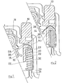
- les fig. 1 et 2 sont des vues en coupe, montrant un bouton-poussoir de test selon l'invention, respectivement en position ouverte et en position enfoncé.
- fig. 1 and 2 are sectional views showing a test push button according to the invention, respectively in the open position and in the depressed position.
Le bouton test est décrit ci-dessous dans son application à un bloc déclencheur différentiel selon le brevet français N° 2437692, auquel on se référera avantageusement pour de plus amples détails, et il suffit de rappeler que le bloc différentiel comporte un bouton test constitué par un bouton dont l'enfoncement permet de simuler un défaut différentiel par insertion d'une résistance électrique d'une manière bien connue des spécialistes. Le bouton test porte un contact mobile 12 venant au contact, en position enfoncé du bouton-poussoir 10, d'un contact semi-fixe 14 constitué par l'extrémité d'un ressort en spirale 16 en appui d'une butée mobile 18. L'extrémité accompagne la butée 18 dans son mouvement et l'ensemble est agencé de telle manière que les contacts 12,14 ne peuvent être fermés qu'à la double condition d'un enfoncement du bouton-poussoir 10 et d'un pivotement de la butée 18 dans une position extrême correspondant à la fermeture du disjoncteur accouplé au bloc différentiel. Lors d'un test de fonctionnement par enfoncement du bouton-poussoir 10, le contact 14 s'efface dès l'ouverture du disjoncteur pour limiter la durée d'alimentation de la résistance de shuntage.The test button is described below in its application to a differential trigger block according to French patent N ° 2437692, which will advantageously be referred to for further details, and it suffices to recall that the differential block comprises a test button constituted by a button, the pressing of which simulates a differential fault by inserting an electrical resistance in a manner well known to specialists. The test button carries a
Le bouton-poussoir 10 présente dans sa partie inférieure un évidement longitudinal 20 ouvert à sa base 22. Dans l'exemple représenté sur les figures, le bouton-poussoir 10 est monté à coulissement en appui d'une face 24 du boîtier du mécanisme et l'évidement 20 est ouvert du côté de la face 24, mais il est clair que l'évidement 20 peut être entièrement fermé sur tous les côtés. L'évidement 20 communique avec une fente 26 ménagée sur la face du bouton-poussoir 10 en regard du contact 14 au voisinage du fond 28 de l'évidement 20. La fente 26 est confinée par un bec de guidage 30 dont la fonction ressortira de la description ci-dessous. Le contact mobile actionné par le bouton-poussoir 10 est constitué par une lame élastique 32 s'étendant longitudinalement à l'intérieur de l'évidement 20 en étant fixée à sa base par une partie repliée 34 à un appui fixe 36 du boîtier. L'extrémité opposée 38 de la lame élastique 32 est recourbée le long du bec 30 pour pénétrer dans la fente 26. Un ressort en spirale de rappel 40 est intercalé entre le bec 30 et la butée fixe 36 pour solliciter le bouton-poussoir 10 en position de repos et d'ouverture de l'interrupteur test. L'ensemble est agencé de telle manière qu'en position d'ouverture de l'interrupteur test l'extrémité 38 de la lame 32 constituant le contact mobile de l'interrupteur est rétractée à l'intérieur de l'évidement 20, empêchant tout risque d'amorçage entre les contacts 14, 38.The
La fig. 2 représente l'interrupteur en position de fermeture et l'on voit que lors de l'enfoncement du bouton-poussoir 10 la lame élastique 32 en appui du fond 28 est repliée pour faire saillir l'extrémité 38 qui vient au contact du contact 14. La déformation de la lame élastique 32 est facilitée et guidée par la forme arrondie du bec 30. Lors de la flexion de la lame élastique 32, la partie rectiligne prend appui sur la face adjacente 24, de manière à éviter les risques de flambage. La partie rectiligne de la lame élastique 32 peut également être guidée par tout moyen approprié. Le ressort de rappel 40 repousse le bouton-poussoir 10 en position de repos et la lame élastique 32 revient automatiquement par sa propre élasticité et éventuellement par l'action du bec 30 en sa position d'origine de rétraction. Il est inutile de noter que l'ensemble est particulièrement simple et que l'encombrement de l'interrupteur selon l'invention est comparable à celui des interrupteurs conventionnels.Fig. 2 shows the switch in the closed position and it can be seen that when the push-
Il est clair que le dispositif de contact à lame élastique rétractable peut être utilisé avec des interrupteurs d'un autre type, par exemple dans lesquels l'extrémité 38 viendrait au contact d'une plage de contact fixe ou s'introduirait dans une pince de contact.It is clear that the contact device with retractable elastic blade can be used with switches of another type, for example in which the
Claims (4)
Applications Claiming Priority (2)
| Application Number | Priority Date | Filing Date | Title |
|---|---|---|---|
| FR8208318 | 1982-05-11 | ||
| FR8208318A FR2526995A1 (en) | 1982-05-11 | 1982-05-11 | TEST BUTTON FOR A DIFFERENTIAL TRIGGER |
Publications (2)
| Publication Number | Publication Date |
|---|---|
| EP0094859A1 EP0094859A1 (en) | 1983-11-23 |
| EP0094859B1 true EP0094859B1 (en) | 1985-12-18 |
Family
ID=9273986
Family Applications (1)
| Application Number | Title | Priority Date | Filing Date |
|---|---|---|---|
| EP19830400874 Expired EP0094859B1 (en) | 1982-05-11 | 1983-05-02 | Test button for a differential trip device |
Country Status (4)
| Country | Link |
|---|---|
| EP (1) | EP0094859B1 (en) |
| DE (1) | DE3361545D1 (en) |
| ES (1) | ES8403239A1 (en) |
| FR (1) | FR2526995A1 (en) |
Families Citing this family (2)
| Publication number | Priority date | Publication date | Assignee | Title |
|---|---|---|---|---|
| DE10329115B4 (en) * | 2003-06-27 | 2005-09-29 | Siemens Ag | Protection switching device with test button |
| DE102004005985A1 (en) * | 2004-02-06 | 2005-09-08 | Siemens Ag | Residual Current Circuit breaker |
Family Cites Families (3)
| Publication number | Priority date | Publication date | Assignee | Title |
|---|---|---|---|---|
| US3789268A (en) * | 1972-12-29 | 1974-01-29 | Gen Electric | Miniature circuit breaker with electronic tripping means |
| FR2241868B1 (en) * | 1973-08-20 | 1976-06-18 | Merlin Gerin | |
| FR2437692A1 (en) * | 1978-09-28 | 1980-04-25 | Merlin Gerin | Manually operated circuit breaker with overload cut=out - has earth fault current overload device and reset units as separate components which may be put together later |
-
1982
- 1982-05-11 FR FR8208318A patent/FR2526995A1/en active Granted
-
1983
- 1983-05-02 DE DE8383400874T patent/DE3361545D1/en not_active Expired
- 1983-05-02 EP EP19830400874 patent/EP0094859B1/en not_active Expired
- 1983-05-06 ES ES522180A patent/ES8403239A1/en not_active Expired
Also Published As
| Publication number | Publication date |
|---|---|
| FR2526995B1 (en) | 1985-02-08 |
| ES522180A0 (en) | 1984-03-16 |
| ES8403239A1 (en) | 1984-03-16 |
| EP0094859A1 (en) | 1983-11-23 |
| DE3361545D1 (en) | 1986-01-30 |
| FR2526995A1 (en) | 1983-11-18 |
Similar Documents
| Publication | Publication Date | Title |
|---|---|---|
| EP0140761B1 (en) | Operating mechanism for a low-voltage multi-pole circuit breaker | |
| FR2360171A1 (en) | CIRCUIT BREAKER CONTROL MECHANISM | |
| FR2361737A1 (en) | CIRCUIT BREAKER WITH LOCKING DEVICE FOR THE CONTROL HANDLE IN THE EVENT OF WELDING OF THE CONTACTS | |
| ES2164593B1 (en) | DETECTION DEVICE FROM GROUND TO EARTH. | |
| FR2623327A1 (en) | MINIATURIZED THERMAL CIRCUIT BREAKER FOR PRINTED CIRCUIT BOARD | |
| EP1542253A1 (en) | Signalling device indicating the triggering of an electrical protection device | |
| EP0094859B1 (en) | Test button for a differential trip device | |
| EP0202162A1 (en) | Device for supplying electric power with a circuit-breaker and electrical plug comprising such a device | |
| FR2908554A1 (en) | Ground fault circuit breaker for distribution network, has testing button including actuating flexible arms laterally extending from base part of button and with ends arranged in opposite and above actuating rod of actuator switch | |
| FR2489587A1 (en) | Leakage current breaker with test circuit - uses touch control test switch to insert resistance in test circuit | |
| FR2685544A1 (en) | OPERATION INDICATOR TYPE FUSE CARTRIDGE. | |
| EP0547928A1 (en) | Protective switch | |
| FR2518312A1 (en) | AUXILIARY AND SIGNALING SWITCHES PREFERABLY TORQUE TO A CIRCUIT BREAKER | |
| FR2767602A1 (en) | DEVICE FOR SIGNALING AN ELECTRICAL FAULT IN A SWITCHING DEVICE SUCH AS A DIFFERENTIAL SWITCH | |
| EP0653719A1 (en) | Electronic switch in particular for the detection of the presence of an IC card in a card reader | |
| FR2644576A3 (en) | TAPE MEASURE | |
| EP3640965B1 (en) | Measuring device and electrical switching apparatus | |
| EP0295167B1 (en) | Test unit for electrical differential protection apparatus and apparatus incorporating this unit | |
| FR2581790A1 (en) | Clean-break circuit breaker switch. | |
| FR2581479A1 (en) | ELECTRIC SWITCH, FOR EXCLUSIVE CIRCUIT-BREAKER WITH SURE INDICATION OF THE SWITCHING POSITION | |
| EP0335755B1 (en) | Safety device for electrical conduit shunt connectors | |
| EP0033409A2 (en) | Trigger operated tool handle switch | |
| FR2500957A1 (en) | MECHANISM FOR LEAKAGE CURRENT TRIGGER COMBINED WITH A LINE PROTECTION CIRCUIT BREAKER | |
| EP1505619A1 (en) | Ameliorated lock mechanism for circuit breakers and circuit breaker incorporating such lock | |
| EP1014401B1 (en) | Device to connect electrically a braid to a contact, mainly for a circuit breaker, contact and holder adapted to this device and breaking apparatus including this device |
Legal Events
| Date | Code | Title | Description |
|---|---|---|---|
| PUAI | Public reference made under article 153(3) epc to a published international application that has entered the european phase |
Free format text: ORIGINAL CODE: 0009012 |
|
| AK | Designated contracting states |
Designated state(s): BE CH DE GB IT LI NL SE |
|
| 17P | Request for examination filed |
Effective date: 19831216 |
|
| ITF | It: translation for a ep patent filed |
Owner name: INTERPATENT ST.TECN. BREV. |
|
| GRAA | (expected) grant |
Free format text: ORIGINAL CODE: 0009210 |
|
| AK | Designated contracting states |
Designated state(s): BE CH DE GB IT LI NL SE |
|
| REF | Corresponds to: |
Ref document number: 3361545 Country of ref document: DE Date of ref document: 19860130 |
|
| PLBE | No opposition filed within time limit |
Free format text: ORIGINAL CODE: 0009261 |
|
| STAA | Information on the status of an ep patent application or granted ep patent |
Free format text: STATUS: NO OPPOSITION FILED WITHIN TIME LIMIT |
|
| 26N | No opposition filed | ||
| PGFP | Annual fee paid to national office [announced via postgrant information from national office to epo] |
Ref country code: NL Payment date: 19870531 Year of fee payment: 5 |
|
| PG25 | Lapsed in a contracting state [announced via postgrant information from national office to epo] |
Ref country code: SE Effective date: 19890503 |
|
| PG25 | Lapsed in a contracting state [announced via postgrant information from national office to epo] |
Ref country code: LI Effective date: 19890531 Ref country code: CH Effective date: 19890531 |
|
| PG25 | Lapsed in a contracting state [announced via postgrant information from national office to epo] |
Ref country code: NL Effective date: 19891201 |
|
| NLV4 | Nl: lapsed or anulled due to non-payment of the annual fee | ||
| REG | Reference to a national code |
Ref country code: CH Ref legal event code: PL |
|
| ITTA | It: last paid annual fee | ||
| PGFP | Annual fee paid to national office [announced via postgrant information from national office to epo] |
Ref country code: GB Payment date: 19930420 Year of fee payment: 11 |
|
| PGFP | Annual fee paid to national office [announced via postgrant information from national office to epo] |
Ref country code: DE Payment date: 19930524 Year of fee payment: 11 |
|
| PGFP | Annual fee paid to national office [announced via postgrant information from national office to epo] |
Ref country code: BE Payment date: 19930616 Year of fee payment: 11 |
|
| PG25 | Lapsed in a contracting state [announced via postgrant information from national office to epo] |
Ref country code: GB Effective date: 19940502 |
|
| PG25 | Lapsed in a contracting state [announced via postgrant information from national office to epo] |
Ref country code: BE Effective date: 19940531 |
|
| BERE | Be: lapsed |
Owner name: MERLIN GERIN Effective date: 19940531 |
|
| GBPC | Gb: european patent ceased through non-payment of renewal fee |
Effective date: 19940502 |
|
| EUG | Se: european patent has lapsed |
Ref document number: 83400874.0 Effective date: 19900412 |
|
| PG25 | Lapsed in a contracting state [announced via postgrant information from national office to epo] |
Ref country code: DE Effective date: 19950201 |