EP0094432B1 - Flüssigkristallanzeigeeinheit - Google Patents
Flüssigkristallanzeigeeinheit Download PDFInfo
- Publication number
- EP0094432B1 EP0094432B1 EP82903343A EP82903343A EP0094432B1 EP 0094432 B1 EP0094432 B1 EP 0094432B1 EP 82903343 A EP82903343 A EP 82903343A EP 82903343 A EP82903343 A EP 82903343A EP 0094432 B1 EP0094432 B1 EP 0094432B1
- Authority
- EP
- European Patent Office
- Prior art keywords
- liquid crystal
- molecules
- phase
- smectic
- cell
- Prior art date
- Legal status (The legal status is an assumption and is not a legal conclusion. Google has not performed a legal analysis and makes no representation as to the accuracy of the status listed.)
- Expired
Links
Images

Classifications
-
- G—PHYSICS
- G02—OPTICS
- G02F—OPTICAL DEVICES OR ARRANGEMENTS FOR THE CONTROL OF LIGHT BY MODIFICATION OF THE OPTICAL PROPERTIES OF THE MEDIA OF THE ELEMENTS INVOLVED THEREIN; NON-LINEAR OPTICS; FREQUENCY-CHANGING OF LIGHT; OPTICAL LOGIC ELEMENTS; OPTICAL ANALOGUE/DIGITAL CONVERTERS
- G02F1/00—Devices or arrangements for the control of the intensity, colour, phase, polarisation or direction of light arriving from an independent light source, e.g. switching, gating or modulating; Non-linear optics
- G02F1/01—Devices or arrangements for the control of the intensity, colour, phase, polarisation or direction of light arriving from an independent light source, e.g. switching, gating or modulating; Non-linear optics for the control of the intensity, phase, polarisation or colour
- G02F1/13—Devices or arrangements for the control of the intensity, colour, phase, polarisation or direction of light arriving from an independent light source, e.g. switching, gating or modulating; Non-linear optics for the control of the intensity, phase, polarisation or colour based on liquid crystals, e.g. single liquid crystal display cells
- G02F1/132—Thermal activation of liquid crystals exhibiting a thermo-optic effect
-
- G—PHYSICS
- G02—OPTICS
- G02F—OPTICAL DEVICES OR ARRANGEMENTS FOR THE CONTROL OF LIGHT BY MODIFICATION OF THE OPTICAL PROPERTIES OF THE MEDIA OF THE ELEMENTS INVOLVED THEREIN; NON-LINEAR OPTICS; FREQUENCY-CHANGING OF LIGHT; OPTICAL LOGIC ELEMENTS; OPTICAL ANALOGUE/DIGITAL CONVERTERS
- G02F1/00—Devices or arrangements for the control of the intensity, colour, phase, polarisation or direction of light arriving from an independent light source, e.g. switching, gating or modulating; Non-linear optics
- G02F1/01—Devices or arrangements for the control of the intensity, colour, phase, polarisation or direction of light arriving from an independent light source, e.g. switching, gating or modulating; Non-linear optics for the control of the intensity, phase, polarisation or colour
- G02F1/13—Devices or arrangements for the control of the intensity, colour, phase, polarisation or direction of light arriving from an independent light source, e.g. switching, gating or modulating; Non-linear optics for the control of the intensity, phase, polarisation or colour based on liquid crystals, e.g. single liquid crystal display cells
- G02F1/137—Devices or arrangements for the control of the intensity, colour, phase, polarisation or direction of light arriving from an independent light source, e.g. switching, gating or modulating; Non-linear optics for the control of the intensity, phase, polarisation or colour based on liquid crystals, e.g. single liquid crystal display cells characterised by the electro-optical or magneto-optical effect, e.g. field-induced phase transition, orientation effect, guest-host interaction or dynamic scattering
- G02F1/13781—Devices or arrangements for the control of the intensity, colour, phase, polarisation or direction of light arriving from an independent light source, e.g. switching, gating or modulating; Non-linear optics for the control of the intensity, phase, polarisation or colour based on liquid crystals, e.g. single liquid crystal display cells characterised by the electro-optical or magneto-optical effect, e.g. field-induced phase transition, orientation effect, guest-host interaction or dynamic scattering using smectic liquid crystals
Definitions
- This invention relates to liquid crystal display apparatus.
- a previously proposed liquid crystal display apparatus which employs a liquid crystal display cell that is written to by heat from a laser beam is characterised in that a light scattering centre is formed by the laser beam irradiation.
- the theory thereof will now briefly be described with reference to a smectic liquid crystal. As its temperature rises, a smectic liquid crystal changes in phase in the following order: a crystal phase, a smectic C phase, a smectic A phase, a nematic phase and an isotropic phase.
- the temperature of the liquid crystal is set at a temperature between the temperature at which the phase transition from the smectic C phase to the smectic A phase occurs and the temperature at which the phase transition from the smectic A phase to the nematic phase occurs, namely at a temperature at which the smectic A phase is maintained.
- the liquid crystal molecules exhibit a layer-like structure and the molecules in each layer are orientated in a direction normal (perpendicular) to the layer. If the liquid crystal molecules are placed on a glass substrate which is subjected to surface treatment in advance, the molecules will be arranged in layers perpendicular to the surface of the glass substrate.
- a laser beam is focussed and irradiated on the liquid crystal layers arranged as described above, heat is generated in the portion thereof irradiated by the laser beam and the heat is conducted to the liquid crystal so that the temperature of the liquid crystal rises to exceed the smectic A-nematic phase transition temperature and, further, to exceed the nematic-isotropic phase transition temperature, whereby the liquid crystal is in the isotropic phase. If, in this state, the irradiation by the laser beam is stopped, the heated isotropic phase portion is cooled and, as a result, tends to return to the smectic A phase.
- the heated portion of the liquid crystal is quenched (cooled rapidly), it is not returned to the initial state in which its molecules are aligned or orientated regularly. Instead, it stays in a condition of disordered orientation, whereby that portion is written to as a memory. If a voltage is applied to the liquid crystal cell which has been written to as described above, the dielectric constant in the long axis direction of the liquid crystal molecules being larger than that in the short axis direction, the liquid crystal molecules (arranged in the disordered state) are returned to the regular alignment of layers, thereby erasing the written information. That is, on the basis of such theory of operation, if the laser beam scans the liquid crystal and the intensity of the laser beam is modulated in synchronism therewith, writing and subsequent erasing of an image can be performed.
- the smectic-nematic phase transition or the nematic-isotropic phase transition is the primary phase transition, latent heat is required to cause the phase transition.
- some of the heat energy from the laser beam by which the liquid crystal is irradiated upon writing does not contribute to raising the temperature, which is a great obstacle to increasing the writing speed.
- a sufficiently scattered state for keeping the written display as the memory must be achieved and, for that purpose, quenching is required.
- the rise in temperature upon heating by the laser beam must be as large as possible, it is quite disadvantageous for any loss to occur in the heat energy brought about by the irradiation by the laser beam.
- the use of the scattered state as the written state makes it difficult to increase the contrast. That is, if, in order to solve the above-mentioned problem, a laser absorbing layer (for example of aluminium) is formed on the liquid crystal cell for the purpose of converting the light energy of the irradiated laser beam into heat energy to the maximum extent possible, the light absorbing efficiency is increased to thereby increase the writing efficiency and the display system becomes of the reflective type, so that a high contrast cannot be obtained as is the case for display system of the transparent (transmitting) type.
- a laser absorbing layer for example of aluminium
- EP-A-0 032 362 discloses a liquid crystal display apparatus comprising:
- liquid crystal cell having a pair of opposed substrates and a chiral smectic C phase liquid crystal disposed between the substrates, the gap between the substrates being sufficiently thin that the helical configuration of the chiral smectic C phase is suppressed;
- the present invention provides a liquid crystal display apparatus as just set forth, characterised in that:
- such an apparatus enables a significant improvement of writing speed and also can be embodied as to enable a high contrast display to be provided.
- the embodiment employs liquid crystal molecules that form a smectic liquid crystal which is in the smectic C phase.
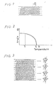
- the smectic C phase has a layer structure common to the smectic phases. While the long axes of the molecules in the layers of the smectic A phase are normal (perpendicular) to the layers, the smectic C phase is characterised by the long axes of the molecules being inclined from the normal to the layers by an angle 8, as is shown in Figure 1.
- the angle 8 is dependent on temperature. That is, as shown in Figure 2, as the temperature of the smectic C phase rises the angle 8 thereof approaches zero and becomes zero at a centre temperature Tc. Since the state where the angle 8 equals zero is the smectic A phase, the temperature Tc is the phase transition temperature at which the smectic C phase changes to the smectic A phase.
- the smectic C phase can be changed to a chiral smectic C phase (SmC * ) by introducing an optical activity centre thereto: the material, in this state, exhibits ferroelectricity.
- the chiral smectic C phase is characterised by a helical structure in which, as shown in Figure 3, the long axis of each of the liquid crystal molecules in the respective layers is inclined by a certain angle 8 from the normal to the layers in the same way as in the respective layers of the smectic C phase, but the liquid crystal molecules in adjacent layers are rotated with respect to one another with the normal to the layers being the axis of rotation.
- the dipole moment of each molecule is perpendicular to the plane formed by the long axis of the molecule and the normal, and is in the direction of the short axis of the molecule.
- liquid crystals having such a chiral smectic C phase are p-decyloxy-benzylidene-p'-amino-2-methyl butyl cinnamate (DOBAMBC) and p-hexyloxy-benzylidene-p'-amino-2 chloropropyl cinnamate (HOBACPC).
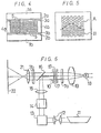
- a liquid crystal display cell formed of the above-mentioned liquid crystal, which can be used in the liquid crystal apparatus embodying this invention, can be constructed as shown in Figure 4.
- This liquid crystal display cell comprises, for example, transparent electrodes 2a and 2b provided on surfaces of glass substrates 1a and 1b, respectively, horizontal orientation layers 3a and 3b (obtained by spin coating of polyvinyl alcohol, for example, without rubbing) provided on the transparent electrodes 2a and 2b, respectively, the horizontal orientation layers being disposed to face each other and being separated by a gap of approximately several micrometres, spacers 4a and 4b disposed at respective ends of the glass substrates to form a space, and a liquid crsytal (for example DOBAMBC) sealed within such space.
- the liquid crystal comprises layers 5.
- the liquid crystal display cell formed as described above cannot have the helical structure shown in Figure 3, even within the temperature range of the chiral smectic C phase (smectic C * phase), but has a structure as shown in Figure 4.
- the reason for this is that, since the cell is of low thickness, a strong array restriction force on the glass surface acts strongly to prevent the liquid crystal molecules from adopting the helical structure.
- the liquid crystal can adopt two different parallel orientations or alignments, shown at A and B respectively, with respect to the glass surfaces.
- the two orientations A and B appear as domains which are equivalent in energy, but of which the directions of the dipole moments of the molecules are opposite to each other. Accordingly, if a DC voltage is applied thereto to change the polarity thereof, either of the two orientations can be selected so that a bistable switching operation is possible.
- liquid crystal display apparatus embodying the invention which includes the liquid crystal display cell having the structure as described above, other parts than the liquid crystal display cell are the same as those of known liquid crystal display apparatus.
- FIG. 6 shows an example of the liquid crystal display apparatus applied to a light display arrangement.
- a laser beam emitted from a laser beam source 11, such as a GaAs laser is directed through a beam expander 12 to a modulator 13 and then focussed at a predetermined position of a liquid crystal display cell or element 10 (constructed as described above) via an X-Y galvanomirror 14, a converging lens 15 and a half mirror 16.
- Part of the laser beam is absorbed by the transparent electrodes 2a and 2b of the liquid crystal display cell 10 and converted to heat, which is then conducted to the liquid crystal layers 5 to raise the temperature at that portion.
- the temperature of the liquid crystal layers 5 is initially set by a heater 17 at a temperature T1 ( Figure 2) at which the liquid crystal molecules are maintained in the chiral smectic C phase. Then, the portion of the liquid crystal layers 5 irradiated by the laser beam is heated to a temperature at which the angle 8 is reduced to zero, namely, to a temperature T2 higher than the chiral smectic C-smectic A phase transition temperature Tc.
- the temperature T1 is preferably set at a value lower than the temperature Tc by about 2 to 10 degrees C.
- the state of the liquid crystal molecules in that case, as shown in Figure 7, is such that the laser beam irradiated portion C is in the smectic A phase.
- the smectic A phase portion is cooled and returns to the smectic C * phase again.
- a weak DC electric field is applied to the cell in its thickness direction, as shown in Figure 5, the polarity thereof can selectively be determined to be either of the orientations A and B, whereby writing to the cell can be effected.
- the orientation A the dipole moments of the liquid crystal molecules are in the upward direction
- the orientation B the dipole moments of the liquid crystal molecules are in the downward direction.
- the applied voltage must be sufficiently low that it cannot switch the molecules between the orientations A and B at the temperature T1.
- the arrangement of the liquid crystal molecules on which writing has been performed as described above is shown in Figure 8.
- the liquid crystal cell 10 (written to as described above) is sandwiched between a polariser 7a and an analyser 7b, a contrast can be established between the written portion and the non-written portion. If the polariser 7a is disposed in the long axis direction of the molecules in the erased state and the analyser 7b is disposed perpendicular thereto, light which is emitted from a light source 18, passed through a condenser 19 and the polariser 7a and then is incident on the liquid crystal display cell 10, is passed through the cell 10 with the linearly polarised light unchanged and interrupted by the analyser 7b so as to be dark.
- the light is affected by double refraction in the cell 10.
- it when emerging from the cell 10, it becomes elliptically polarised light so that part of the light is transmitted through the analyser 7b and projected through a lens 21 onto a display screen 22 to be readable.
- liquid crystal display apparatus embodying the invention is unlike a previously proposed method employing for display a focal conic texture formed by using a phase transition such as the smectic A-isotropic and colesteric-isotropic or the like and quenching thereof, but employs the smectic C *- smectic A phase transition, no latent heat is required and, further, quenching over a large temperature drop is not necessary so that such a large rise of the temperature is not required, thereby enabling a large increase of the writing speed to be achieved.
- a phase transition such as the smectic A-isotropic and colesteric-isotropic or the like and quenching thereof
- the display method of the liquid crystal display embodying the invention is similar to that of a TN liquid crystal display cell, a high contrast can be obtained by a simple optical system. Furthermore, absorption of the laser beam can be carried out by mixing a colouring matter or dye, which has a maximum wavelength in the vicinity of the laser oscillation wavelength, into the liquid crystal layers.
Claims (5)
Applications Claiming Priority (2)
| Application Number | Priority Date | Filing Date | Title |
|---|---|---|---|
| JP56186334A JPS5887535A (ja) | 1981-11-20 | 1981-11-20 | 液晶表示装置 |
| JP186334/81 | 1981-11-20 |
Publications (3)
| Publication Number | Publication Date |
|---|---|
| EP0094432A1 EP0094432A1 (de) | 1983-11-23 |
| EP0094432A4 EP0094432A4 (de) | 1986-03-18 |
| EP0094432B1 true EP0094432B1 (de) | 1989-04-05 |
Family
ID=16186525
Family Applications (1)
| Application Number | Title | Priority Date | Filing Date |
|---|---|---|---|
| EP82903343A Expired EP0094432B1 (de) | 1981-11-20 | 1982-11-19 | Flüssigkristallanzeigeeinheit |
Country Status (6)
| Country | Link |
|---|---|
| US (1) | US4639722A (de) |
| EP (1) | EP0094432B1 (de) |
| JP (1) | JPS5887535A (de) |
| KR (1) | KR840002532A (de) |
| DE (1) | DE3279596D1 (de) |
| WO (1) | WO1983001841A1 (de) |
Families Citing this family (29)
| Publication number | Priority date | Publication date | Assignee | Title |
|---|---|---|---|---|
| USRE34966E (en) * | 1980-01-08 | 1995-06-13 | Clark Noel A | Surface stabilized ferroelectric liquid crystal devices with LC molecules aligned at angle Ω(α) from normal to substrates |
| US4813767A (en) * | 1980-01-08 | 1989-03-21 | Clark Noel A | Surface stabilized ferroelectric liquid crystal devices |
| US4958916A (en) * | 1980-01-08 | 1990-09-25 | Clark Noel A | Surface stabilized ferroelectric liquid crystal devices |
| US4840463A (en) * | 1987-08-19 | 1989-06-20 | Clark Noel A | Surface stabilized ferroelectric liquid crystal devices |
| USRE34950E (en) * | 1980-01-08 | 1995-05-23 | Clark Noel A | Surface stabilized ferroelectric liquid crystal devices with means for aligning LC molecules at Ω(α) from normal to the means |
| US5083855A (en) * | 1980-01-08 | 1992-01-28 | Clark Noel A | Surface stabilized ferroelectric liquid crystal devices |
| GB2067811B (en) * | 1980-01-16 | 1983-08-10 | Standard Telephones Cables Ltd | Co-ordinate addressing of smetic display cells |
| US4655561A (en) * | 1983-04-19 | 1987-04-07 | Canon Kabushiki Kaisha | Method of driving optical modulation device using ferroelectric liquid crystal |
| US4938570A (en) * | 1985-04-18 | 1990-07-03 | Sony Corporation | Method and system for data display and input via display screen |
| JPS61256321A (ja) * | 1985-05-10 | 1986-11-13 | Hitachi Ltd | 液晶投射型表示装置 |
| US4751509A (en) * | 1985-06-04 | 1988-06-14 | Nec Corporation | Light valve for use in a color display unit with a diffraction grating assembly included in the valve |
| GB8606783D0 (en) * | 1986-03-19 | 1986-04-23 | Gen Electric Co Plc | Picture synthesizers |
| GB8608276D0 (en) * | 1986-04-04 | 1986-05-08 | British Telecomm | Optical devices |
| JPS62291624A (ja) * | 1986-06-11 | 1987-12-18 | Hitachi Ltd | 液晶表示装置 |
| JPS6310132A (ja) * | 1986-07-02 | 1988-01-16 | Hitachi Ltd | 液晶表示装置 |
| GB8616165D0 (en) * | 1986-07-02 | 1986-08-06 | Stc Plc | Liquid crystal cell |
| EP0271900B1 (de) * | 1986-12-17 | 1993-12-29 | Canon Kabushiki Kaisha | Verfahren und Gerät zur optischen Aufnahme |
| JP2698357B2 (ja) * | 1987-08-17 | 1998-01-19 | キヤノン株式会社 | 電極間の短絡部分離法及び液晶パネルの製造法 |
| US5026145A (en) * | 1987-09-24 | 1991-06-25 | Asahi Kogaku Kogyo Kabushiki Kaisha | Exposure apparatus |
| JP2551055B2 (ja) * | 1987-11-20 | 1996-11-06 | ソニー株式会社 | 液晶表示装置 |
| NL9002808A (nl) * | 1990-12-19 | 1992-07-16 | Philips Nv | Inrichting ten behoeve van projectieweergave. |
| JPH05150244A (ja) * | 1991-02-20 | 1993-06-18 | Canon Inc | 強誘電液晶素子 |
| JP3263517B2 (ja) * | 1994-02-08 | 2002-03-04 | 株式会社小松製作所 | 液晶マスクマーカの駆動方法 |
| US5731797A (en) * | 1994-10-06 | 1998-03-24 | Matsushita Electric Industrial Co., Ltd. | Driving method for spatial light modulator and projection display system |
| US6275211B1 (en) | 1997-12-05 | 2001-08-14 | Gateway, Inc. | Waste heat actuated display back light |
| AU2002246714A1 (en) * | 2000-12-18 | 2002-08-06 | Sara L. Johnson | 3d display devices with transient light scattering shutters |
| US7631877B2 (en) * | 2006-01-26 | 2009-12-15 | Battenfeld Technologies, Inc. | Firearm targets and methods for manufacturing firearm targets |
| WO2008058142A1 (en) * | 2006-11-06 | 2008-05-15 | University Of Massachusetts | Systems and methods of all-optical fourier phase contrast imaging using dye doped liquid crystals |
| EP3031967B1 (de) * | 2014-12-11 | 2019-02-27 | SIPRA Patententwicklungs- und Beteiligungsgesellschaft mbH | Maschine und Verfahren zur Herstellung von Maschenware |
Family Cites Families (13)
| Publication number | Priority date | Publication date | Assignee | Title |
|---|---|---|---|---|
| US4150396A (en) * | 1974-09-06 | 1979-04-17 | Thomson-Csf | Erasable thermo-optic storage display of a transmitted color image |
| FR2292254A1 (fr) * | 1974-11-21 | 1976-06-18 | Thomson Csf | Procede de visualisation a cristal liquide, dispositif de traitement de l'information appliquant ce procede |
| FR2296198A1 (fr) * | 1974-12-24 | 1976-07-23 | Commissariat Energie Atomique | Procede thermique de commande de proprietes optiques d'un cristal liquide et dispositifs mettant en oeuvre ledit procede |
| FR2404272A1 (fr) * | 1977-09-23 | 1979-04-20 | Thomson Csf | Dispositif de reproduction d'images monochromes et systeme de teletransmission d'images utilisant un tel dispositif |
| US4291948A (en) * | 1977-11-10 | 1981-09-29 | International Standard Electric Corporation | Liquid crystal display incorporating positive and negative smectic material |
| US4563059A (en) * | 1983-01-10 | 1986-01-07 | Clark Noel A | Surface stabilized ferroelectric liquid crystal devices |
| US4367924A (en) * | 1980-01-08 | 1983-01-11 | Clark Noel A | Chiral smectic C or H liquid crystal electro-optical device |
| EP0032362B1 (de) * | 1980-01-10 | 1984-08-22 | Noel A. Clark | Elektro-optische Vorrichtung mit einem chiralen smektischen Flüssigkristall und Verfahren zu ihrer Herstellung |
| FR2489564A1 (fr) * | 1980-09-02 | 1982-03-05 | Thomson Csf | Procede et dispositif de visualisation utilisant un effet thermo-optique avec memoire dans une couche mince de cristal liquide disquotique |
| FR2507802A1 (fr) * | 1981-06-10 | 1982-12-17 | Thomson Csf | Dispositif d'affichage a cristal liquide associant deux modes d'adressage |
| US4514045A (en) * | 1981-06-22 | 1985-04-30 | Minnesota Mining And Manufacturing Company | Helichromic-smectic liquid crystal compositions and display cells |
| US4477151A (en) * | 1981-12-28 | 1984-10-16 | Itt Industries, Inc. | Smectic liquid crystal cell with heat pulse and laser |
| US4479118A (en) * | 1982-02-11 | 1984-10-23 | General Electric Company | Power outage indicator |
-
1981
- 1981-11-20 JP JP56186334A patent/JPS5887535A/ja active Granted
-
1982
- 1982-11-18 KR KR1019820005212A patent/KR840002532A/ko unknown
- 1982-11-19 WO PCT/JP1982/000442 patent/WO1983001841A1/ja active IP Right Grant
- 1982-11-19 DE DE8282903343T patent/DE3279596D1/de not_active Expired
- 1982-11-19 EP EP82903343A patent/EP0094432B1/de not_active Expired
- 1982-11-19 US US06/530,596 patent/US4639722A/en not_active Expired - Fee Related
Also Published As
| Publication number | Publication date |
|---|---|
| EP0094432A1 (de) | 1983-11-23 |
| JPS5887535A (ja) | 1983-05-25 |
| EP0094432A4 (de) | 1986-03-18 |
| WO1983001841A1 (en) | 1983-05-26 |
| DE3279596D1 (en) | 1989-05-11 |
| US4639722A (en) | 1987-01-27 |
| KR840002532A (ko) | 1984-07-02 |
| JPS6230614B2 (de) | 1987-07-03 |
Similar Documents
| Publication | Publication Date | Title |
|---|---|---|
| EP0094432B1 (de) | Flüssigkristallanzeigeeinheit | |
| US3796999A (en) | Locally erasable thermo-optic smectic liquid crystal storage displays | |
| US4196974A (en) | Smectic liquid crystal display cell | |
| US3836243A (en) | Liquid crystal display apparatus | |
| Goodman | Liquid-crystal displays—Electro-optic effects and addressing techniques | |
| KR0140706B1 (ko) | 다층 액정장치 | |
| JPS59216126A (ja) | 液晶装置 | |
| EP0525424B1 (de) | Räumlicher Lichtmodulator mit Flüssigkristall | |
| EP0349731B1 (de) | Einrichtung zur optischen Modulation mit Polymerflüssigkristall | |
| JP3080122B2 (ja) | 表示・記録媒体、表示・記録方法および表示・記録装置 | |
| JP3329565B2 (ja) | 液晶光変調器 | |
| US6304310B1 (en) | Liquid crystal apparatus | |
| EP0395113A2 (de) | Laseradressiertes Flüssigkristall-Lichtventil | |
| GB2218533A (en) | Information storage | |
| Nakamura et al. | Ferroelectric liquid‐crystal light valve addressed by laser heating | |
| JP3071216B2 (ja) | 液晶セルを使用した情報記録装置および画像投影装置 | |
| JP2753206B2 (ja) | ゲストホスト型液晶表示素子 | |
| Nakamura et al. | A novel laser‐addressed smectic liquid‐crystal light valve | |
| JP2877884B2 (ja) | 光熱書込み型空間光変調素子 | |
| Jánossy | Photo-orientation at liquid crystal—polymer interfaces | |
| Klosowicz et al. | Reverse-mode PDLC layers | |
| JPS61118492A (ja) | レ−ザ−熱書き込み用液晶組成物 | |
| Coates | Smectic A LCDs | |
| Zmija et al. | Polymer-dispersed liquid-crystal displays: principles, preparation, properties, and applications | |
| Dewey | Projection Storage Displays Using Laser-Addressed Smectic Liquid Crystals |
Legal Events
| Date | Code | Title | Description |
|---|---|---|---|
| PUAI | Public reference made under article 153(3) epc to a published international application that has entered the european phase |
Free format text: ORIGINAL CODE: 0009012 |
|
| 17P | Request for examination filed |
Effective date: 19830721 |
|
| AK | Designated contracting states |
Designated state(s): DE FR GB NL |
|
| A4 | Supplementary search report drawn up and despatched |
Effective date: 19860318 |
|
| 17Q | First examination report despatched |
Effective date: 19870903 |
|
| GRAA | (expected) grant |
Free format text: ORIGINAL CODE: 0009210 |
|
| AK | Designated contracting states |
Kind code of ref document: B1 Designated state(s): DE FR GB NL |
|
| REF | Corresponds to: |
Ref document number: 3279596 Country of ref document: DE Date of ref document: 19890511 |
|
| ET | Fr: translation filed | ||
| PG25 | Lapsed in a contracting state [announced via postgrant information from national office to epo] |
Ref country code: GB Effective date: 19891119 |
|
| PLBE | No opposition filed within time limit |
Free format text: ORIGINAL CODE: 0009261 |
|
| STAA | Information on the status of an ep patent application or granted ep patent |
Free format text: STATUS: NO OPPOSITION FILED WITHIN TIME LIMIT |
|
| PGFP | Annual fee paid to national office [announced via postgrant information from national office to epo] |
Ref country code: DE Payment date: 19900131 Year of fee payment: 8 |
|
| 26N | No opposition filed | ||
| PG25 | Lapsed in a contracting state [announced via postgrant information from national office to epo] |
Ref country code: NL Effective date: 19900601 |
|
| NLV4 | Nl: lapsed or anulled due to non-payment of the annual fee | ||
| GBPC | Gb: european patent ceased through non-payment of renewal fee | ||
| PG25 | Lapsed in a contracting state [announced via postgrant information from national office to epo] |
Ref country code: FR Effective date: 19900731 |
|
| REG | Reference to a national code |
Ref country code: FR Ref legal event code: ST |
|
| PG25 | Lapsed in a contracting state [announced via postgrant information from national office to epo] |
Ref country code: DE Effective date: 19910801 |