EP0093542A2 - Dispositif pour produire des pulsations dans un liquide - Google Patents
Dispositif pour produire des pulsations dans un liquide Download PDFInfo
- Publication number
- EP0093542A2 EP0093542A2 EP83302252A EP83302252A EP0093542A2 EP 0093542 A2 EP0093542 A2 EP 0093542A2 EP 83302252 A EP83302252 A EP 83302252A EP 83302252 A EP83302252 A EP 83302252A EP 0093542 A2 EP0093542 A2 EP 0093542A2
- Authority
- EP
- European Patent Office
- Prior art keywords
- valve
- circuit
- pressure
- liquid
- period
- Prior art date
- Legal status (The legal status is an assumption and is not a legal conclusion. Google has not performed a legal analysis and makes no representation as to the accuracy of the status listed.)
- Granted
Links
Images


Classifications
-
- B—PERFORMING OPERATIONS; TRANSPORTING
- B01—PHYSICAL OR CHEMICAL PROCESSES OR APPARATUS IN GENERAL
- B01D—SEPARATION
- B01D65/00—Accessories or auxiliary operations, in general, for separation processes or apparatus using semi-permeable membranes
- B01D65/08—Prevention of membrane fouling or of concentration polarisation
-
- A—HUMAN NECESSITIES
- A61—MEDICAL OR VETERINARY SCIENCE; HYGIENE
- A61M—DEVICES FOR INTRODUCING MEDIA INTO, OR ONTO, THE BODY; DEVICES FOR TRANSDUCING BODY MEDIA OR FOR TAKING MEDIA FROM THE BODY; DEVICES FOR PRODUCING OR ENDING SLEEP OR STUPOR
- A61M1/00—Suction or pumping devices for medical purposes; Devices for carrying-off, for treatment of, or for carrying-over, body-liquids; Drainage systems
- A61M1/36—Other treatment of blood in a by-pass of the natural circulatory system, e.g. temperature adaptation, irradiation ; Extra-corporeal blood circuits
- A61M1/3621—Extra-corporeal blood circuits
-
- A—HUMAN NECESSITIES
- A61—MEDICAL OR VETERINARY SCIENCE; HYGIENE
- A61M—DEVICES FOR INTRODUCING MEDIA INTO, OR ONTO, THE BODY; DEVICES FOR TRANSDUCING BODY MEDIA OR FOR TAKING MEDIA FROM THE BODY; DEVICES FOR PRODUCING OR ENDING SLEEP OR STUPOR
- A61M60/00—Blood pumps; Devices for mechanical circulatory actuation; Balloon pumps for circulatory assistance
- A61M60/10—Location thereof with respect to the patient's body
- A61M60/104—Extracorporeal pumps, i.e. the blood being pumped outside the patient's body
- A61M60/109—Extracorporeal pumps, i.e. the blood being pumped outside the patient's body incorporated within extracorporeal blood circuits or systems
- A61M60/113—Extracorporeal pumps, i.e. the blood being pumped outside the patient's body incorporated within extracorporeal blood circuits or systems in other functional devices, e.g. dialysers or heart-lung machines
-
- A—HUMAN NECESSITIES
- A61—MEDICAL OR VETERINARY SCIENCE; HYGIENE
- A61M—DEVICES FOR INTRODUCING MEDIA INTO, OR ONTO, THE BODY; DEVICES FOR TRANSDUCING BODY MEDIA OR FOR TAKING MEDIA FROM THE BODY; DEVICES FOR PRODUCING OR ENDING SLEEP OR STUPOR
- A61M60/00—Blood pumps; Devices for mechanical circulatory actuation; Balloon pumps for circulatory assistance
- A61M60/20—Type thereof
- A61M60/247—Positive displacement blood pumps
- A61M60/253—Positive displacement blood pumps including a displacement member directly acting on the blood
- A61M60/268—Positive displacement blood pumps including a displacement member directly acting on the blood the displacement member being flexible, e.g. membranes, diaphragms or bladders
- A61M60/279—Peristaltic pumps, e.g. roller pumps
-
- A—HUMAN NECESSITIES
- A61—MEDICAL OR VETERINARY SCIENCE; HYGIENE
- A61M—DEVICES FOR INTRODUCING MEDIA INTO, OR ONTO, THE BODY; DEVICES FOR TRANSDUCING BODY MEDIA OR FOR TAKING MEDIA FROM THE BODY; DEVICES FOR PRODUCING OR ENDING SLEEP OR STUPOR
- A61M60/00—Blood pumps; Devices for mechanical circulatory actuation; Balloon pumps for circulatory assistance
- A61M60/30—Medical purposes thereof other than the enhancement of the cardiac output
- A61M60/36—Medical purposes thereof other than the enhancement of the cardiac output for specific blood treatment; for specific therapy
- A61M60/37—Haemodialysis, haemofiltration or diafiltration
-
- A—HUMAN NECESSITIES
- A61—MEDICAL OR VETERINARY SCIENCE; HYGIENE
- A61M—DEVICES FOR INTRODUCING MEDIA INTO, OR ONTO, THE BODY; DEVICES FOR TRANSDUCING BODY MEDIA OR FOR TAKING MEDIA FROM THE BODY; DEVICES FOR PRODUCING OR ENDING SLEEP OR STUPOR
- A61M60/00—Blood pumps; Devices for mechanical circulatory actuation; Balloon pumps for circulatory assistance
- A61M60/50—Details relating to control
- A61M60/508—Electronic control means, e.g. for feedback regulation
- A61M60/538—Regulation using real-time blood pump operational parameter data, e.g. motor current
- A61M60/554—Regulation using real-time blood pump operational parameter data, e.g. motor current of blood pressure
-
- A—HUMAN NECESSITIES
- A61—MEDICAL OR VETERINARY SCIENCE; HYGIENE
- A61M—DEVICES FOR INTRODUCING MEDIA INTO, OR ONTO, THE BODY; DEVICES FOR TRANSDUCING BODY MEDIA OR FOR TAKING MEDIA FROM THE BODY; DEVICES FOR PRODUCING OR ENDING SLEEP OR STUPOR
- A61M60/00—Blood pumps; Devices for mechanical circulatory actuation; Balloon pumps for circulatory assistance
- A61M60/80—Constructional details other than related to driving
- A61M60/845—Constructional details other than related to driving of extracorporeal blood pumps
- A61M60/851—Valves
- A61M60/853—Valves the valve being formed by a flexible tube element which is clamped for restricting the flow
-
- B—PERFORMING OPERATIONS; TRANSPORTING
- B01—PHYSICAL OR CHEMICAL PROCESSES OR APPARATUS IN GENERAL
- B01D—SEPARATION
- B01D2313/00—Details relating to membrane modules or apparatus
- B01D2313/08—Flow guidance means within the module or the apparatus
-
- B—PERFORMING OPERATIONS; TRANSPORTING
- B01—PHYSICAL OR CHEMICAL PROCESSES OR APPARATUS IN GENERAL
- B01D—SEPARATION
- B01D2313/00—Details relating to membrane modules or apparatus
- B01D2313/18—Specific valves
-
- B—PERFORMING OPERATIONS; TRANSPORTING
- B01—PHYSICAL OR CHEMICAL PROCESSES OR APPARATUS IN GENERAL
- B01D—SEPARATION
- B01D2313/00—Details relating to membrane modules or apparatus
- B01D2313/24—Specific pressurizing or depressurizing means
- B01D2313/243—Pumps
-
- B—PERFORMING OPERATIONS; TRANSPORTING
- B01—PHYSICAL OR CHEMICAL PROCESSES OR APPARATUS IN GENERAL
- B01D—SEPARATION
- B01D2313/00—Details relating to membrane modules or apparatus
- B01D2313/90—Additional auxiliary systems integrated with the module or apparatus
- B01D2313/903—Integrated control or detection device
-
- B—PERFORMING OPERATIONS; TRANSPORTING
- B01—PHYSICAL OR CHEMICAL PROCESSES OR APPARATUS IN GENERAL
- B01D—SEPARATION
- B01D2321/00—Details relating to membrane cleaning, regeneration, sterilization or to the prevention of fouling
- B01D2321/20—By influencing the flow
- B01D2321/2066—Pulsated flow
Definitions
- the present invention relates to an apparatus for producing pulses in liquid, of the type which is designed for supplying liquid by means of a roller pump into a membrane unit having membranes provided therein in such a way that liquid is introduced in a pulsed state into the membrane unit by periodically opening and closing a flow path by means of a valve disposed in the flow path on the inlet side or outlet side of the membrane unit.
- the apparatus of the invention may be advantageously employed in blood treating apparatuses such as those for hemodialysis, hemofiltration, and plasmapheresis, and body cavity fluid treating apparatuses such as those for ascitic fluid filtration, ascitic fluid concentration, and pleural fluid concentration.
- roller pumps used for hemodialysis purposes today it is seen that the rollers move forward while compressing the blood circuit; therefore, it is obvious that pulses, though insignificant, can be caused to the blood.
- the proposed method it is said, will permit a reduction of resistance due to material transfer, correction of channelling, and increase of effective membrane area, through the supply of blood in a much higher degree of pulsed state than that usually produced by the membrane unit and roller pump, so that some 10% improvement can be obtained in hemodialysis efficiency.
- said method has an additional advantage that in a little anticoagulant hemodialysis as well as in non-anticoagulant hemolysis, blood coagulation and blood residue within the membrane unit can be reduced to some extent.
- an apparatus for producing pulses in liquid which comprises a roller pump, a membrane unit incorporating membranes, a valve for opening and closing a flow path of the liquid being transferred by the pump, start-pressure signalling means for intermittently producing a close-valve signal to said valve, a synchronous monitor circuit for converting the period of such a signal into a voltage value or pulse member, a pressure-period setting circuit for setting a pressure period correlated to the period of said start-pressure signal, and a comparator circuit for continually transmitting the close-valve signal until an integrated voltage value or pulse number since the start of pressure application concurs with the monitored value at said monitor circuit.
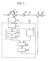
- FIG. 1 is an illustrative representation of the apparatus according to the invention. As shown, the apparatus comprises a roller pump 1, a liquid transfer conduit 11, a membrane unit 30, a valve 2, start-pressure signalling means 3, and a control circuit 12 for producing pulses.
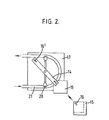
- the roller pump 1 is such that rollers 20 are pressed against a tube 21 as they move, thereby compressing the tube 21 so that liquid in the tube 21 is moved forwardly in successive order.
- the number of rollers 20 can be suitably determined according to the required rate of liquid transfer.
- a 2-roller type pump is normally used.
- the liquid transfer conduit 11 may be a stainless-steel pipe or a resin tube, or a flexible plastics tube.
- a flexible PVC tube is usually employed for transfer of blood or the like. Where such a flexible tube is used, the pressure applied to the interior of the tube while the tube is shut off by the valve can be absorbed through inflation of the tube. Where a rigid tube, e.g. a stainless-steel tube, is used, however, a prolonged shut-off period may result in pump break-down because the tube has no means to absorb the pressure. Therefore, in the case of a rigid tube being used, it is desirable that a chamber 13 for pressure absorption be provided in the line.
- the membrane unit 30 incorporates membranes of hollow fiber shape or cylindrical shape or of the flat plate shape.
- such membranes may be formed of ethylenevinyl alcohol copolymer, cellulose derivative such as cellulose acetate of the like, polyolefin, polyacrylonitrile, polyamide, polyester, or polysulfone.
- the membranes are housed in the unit 30 in a known manner.
- the valve 2 connected to the transfer conduit 11 is an automatic valve adapted to be automatically opened and closed. It is such that when power is switched on the flow path is disconnected, or in other words, when the apparatus is not in use, or when power is switched off, the flow path is connected.
- the valve 2 is usually a pinch valve of the direct acting type, but for industrial purposes, the valve 2 may be a shut-off valve of some other type, for example, a ball valve or sluice valve, said valve 2 may be connected to the transfer conduit 11 on the inlet side or on the outlet side. Usually, it is preferably attached to the transfer conduit 11 on the inlet side of the membrane unit 30.
- the valve 2 is usually solenoid-operated, but where it is of a large type, the valve 2 may be operated by an air cylinder or electric motor. The valve 2 may be remote controlled through electric or pneumatic signals.
- the start-pressure signalling means 3 transmits to the control circuit 12 a signal for shutting down the valve 2.
- said signalling means 3 comprises a rotating plate 14 mounted on the rotating shaft of the roller pump 1 and incorporating magnets 16', and a magnetic proximity switch 16 provided on a movable plate 15 removably attached to a rotary guide 17 of the pump 1.
- the signalling means 3 is switched on by action of the magnet 16' to transmit a start-pressure signal.
- Said signalling means 3 give a valve-close start signal to the control circuit 12.
- a phototube or a limit switch may be used.
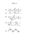
- said signalling means 3 give a pulse (a) which is proportional to the number of pump revolutions, of such form as shown in Figure 3(1).
- the control circuit 12 for pulsation adapted to set a shut-down period for the valve closed according to the signal from said signalling means 3, comprises a wave shaping circuit 4, a synchronous monitor circuit 5, pressure-period setting circuit 8, a comparator circuit 9, and a drive circuit 10.
- pulses transmitted by said start-pressure signalling means are shaped into such short wave form (b) as shown in Figure 3(2).
- the synchronous monitor circuit 5 is to transform the period of the signal (b) from the wave shaping circuit 4 into a voltage value or pulse number.
- This circuit 5 comprises an integration circuit for integrating voltage values or pulse numbers, a resetting circuit, a voltage-value or pulse-number conversion circuit 6 for shaping reference waves (c) of sawtooth shape having a ramp inclination of ( ⁇ 0 ), and a memory circuit 7 for storing a maximal value (d) of the voltage values or pulse-numbers integrated at said integration circuit.
- the interval L of pulses (a) is short, or in other words, the rate of pump rotation is large, the interval between reference waves (c) of sawtooth shape having a ramp inclination of (9 0 ) is short, and the maximal valve (d) of the waves is low. Conversely, if the rate of the pump rotation is small, the maximal value (d) of the waves is high.
- the pressure-period setting circuit 8 sets the period of valve shut-off until the pressure of the liquid in the tube reaches a prescribed pressure.
- This circuit 8 may be constituted of the same circuit that is used as said voltage-value or pulse-number conversion circuit 6. That is, the circuit 8 comprises an integration circuit for integrating voltage values or pulse numbers (e) which tend to become larger at ramp inclination (8) set by the start-pressure signal, and a resetting circuit.
- the resetting circuit is provided in common with that of said conversion circuit 6; so, the starting point of voltage-value or pulse-number integration may be same for the both resetting circuits.
- the period of pressure application may be set according to the ramp inclination (0) of the voltage value or pulse value which tends to increase in proportion to time beginning from the point of the start-pressure signal input.
- the comparator circuit 9 compares the voltage values or pulse value (e) integrated at ramp inclination (8) set at the setting circuit 8 with the maximal voltage or pulse value (d) stored at said memory circuit 7, so that a close-valve signal (f) is given to the drive circuit 10 to close the valve for a period until the voltage or pulse value (e) exceeds the stored maximal voltage or pulse value (d). That is, the valve is closed as long as said signal (f) is given, and when such period of close-value signalling ends, the valve is opened and another series of pulses occur, then the valve is closed again.
- Figure 4 is an illustrative view showing the pattern of operation when the rate of roller-pump run is relatively slow, with ramp inclination kept constant.
- pulse interval is increased from L 1 to L 2 as Figure 4(1) shows.
- the converted voltage or pulse value (d 2 ) is greater than the original converted value (d 1 ), as Figure 4(2) shows.
- the voltage value or pulse value (e) tends to increase at the set ramp inclination ( ⁇ 1 )
- close-valve signals (f 1 ), (f 2 ) are given until said voltage or pulse value (e) concurs with the stored converted values (d 1 ), (d 2 ), as Figure 4(3) shows. Therefore, between cycles (5 1 ), (S 2 ) and close-valve periods (f 1 ), (f 2 ) in the cycles, the following relation holds:
- the period of valve closing in a cycle may always be kept constant irrespective of the rotational speed of the roller pump 1.
- the rate of liquid pressure rise amplitude of pulsation
- any change in the rotational speed of the roller pump 1 will not cause an abnormal pressure to be applied to the membrane unit 30, with no damage caused to the membranes; this assures safe operation of the apparatus.
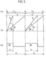
- FIG. 5 there is shown a case where the setting of the pressure application period, that is, ramp inclination is changed from (91) to ( ⁇ 2 ), with the rotational speed of the pump 1 (pulse interval) kept constant at L.
- the rotational speed is constant, and therefore, the maximal converted voltage or pulse value (d) is constant, as Figure 5(2) shows.
- close-valve signals (f 1 ), (f 2 ) are given until integrated voltage or pulse values rising with ramp inclination (9 1 ) and ( ⁇ 2 ) concur with said maximal converted value (d), as Figure 5(3) shows.
- the close-valve period is made proportionally longer, that is, from (f 1 ) to (f2), whereby pulses of large amplitude can be produced.
- Said synchronous monitor circuit, pressure-application period setting circuit, and comparator circuit may incorporate microcomputers.
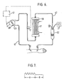
- FIG. 6 shows an example in which the apparatus of the invention is applied for the purpose of hemodialysis.
- hemodialysis requires an extracorporeal blood circulating circuit such that the blood introduced from a human arterial canal into an artery-side circuit 41 is supplied by means of a roller pump 1 into a membrane unit 30 incorporating hollow fibers 31; after metabolized with a dialysate introduced into the unit 30, the blood is returned through a venous-side circuit 42 into the human body via an air chamber 32.
- an automatic pinch valve 2 adapted to be automatically opened and closed.
- Shown at 37 is a pressure gauge attached to the air chamber 32.
- Said pinch valve 2 is such that the open/close period for the valve (that is, amplitude of pulsation) is controlled by start-pressure signalling means 3 attached to the roller pump 1 and a control circuit 12 for setting the close-valve period. If the pinch valve 2 is closed, the blood is subjected to pressure between the valve 2 and the roller pump 1; and after a certain period, if the valve 2 is opened, the blood is supplied into the membrane unit 30 under pressure. Therefore, by periodically opening and closing the valve 2 it is possible to produce pulse waves as shown in Figure 7.
- the roller pump of the 2-roller type, is run at 20 rpm to supply blood into the membrane unit 30 at the rate of 200 mVhr, with close-valve period set at 0.5 sec. Zone A represents a period during which the valve 2 is closed to produce pulses; and zone B represents a period during the valve 2 is opened. It is noted that during the zone-B period there is produced a slight degree of pulsation by the roller pump 1.
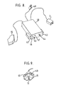
- the control circuit 12 is housed in a box 40 shown in Figure 8.
- a power switch 45 On the front panel of said box 40 there are provided a power switch 45, a power-supply indicator lamp 46, an output indicator lamp 47, and an adjusting member 44 for pressure-application period setting.
- magnets 43 On both sides of the box 40 there are provided magnets 43 for removably attaching the box 40 to the side wall of the roller pump 1.
- a power-supply plug 48 At the rear end of the box 40 there are provided a power-supply plug 48, a plate 15 attachable to the roller pump 1, and terminals for connecting lead wires attached to the pinch valve 2.
- the plate 15 to be attached to the roller pump 1 is provided on its interior with a proximity switch 16, as Figure 9 shows.
- FIG. 10 shows an example in which the box 40 with the control circuit housed therein, and the plate 15 with the proximity switch 16 housed therein, are attached to the roller pump 1, the box 40 being attached to a side wall of the roller pump 1 through the magnets 43 provided on the side wall of the box 40.
- the plate 15 is attached to the rotary guide 17 at a corner thereof by means of the magnets 49.
- the apparatus according to the invention is adapted to correlate the rotating speed of the pump 1 with the period of pressure application, so that the amount of pressure applied can always be maintained constant.
- set valve for pressure-application period can readily be changed so that any possible danger due to pressure rise can be effectively forestalled.
- the apparatus of the invention is geared to ease of practical application in such a way that any existing roller pump can be effectively employed in producing pulses, only by attaching start-pressure signalling means thereto. Another advantage is that the apparatus is simple in construction, substantially trouble-free, and low in cost.
Landscapes
- Health & Medical Sciences (AREA)
- Heart & Thoracic Surgery (AREA)
- Engineering & Computer Science (AREA)
- Cardiology (AREA)
- Veterinary Medicine (AREA)
- Public Health (AREA)
- Biomedical Technology (AREA)
- Hematology (AREA)
- Life Sciences & Earth Sciences (AREA)
- Animal Behavior & Ethology (AREA)
- General Health & Medical Sciences (AREA)
- Anesthesiology (AREA)
- Mechanical Engineering (AREA)
- Vascular Medicine (AREA)
- Urology & Nephrology (AREA)
- Pulmonology (AREA)
- Chemical & Material Sciences (AREA)
- Chemical Kinetics & Catalysis (AREA)
- External Artificial Organs (AREA)
Applications Claiming Priority (2)
| Application Number | Priority Date | Filing Date | Title |
|---|---|---|---|
| JP74169/82 | 1982-04-30 | ||
| JP57074169A JPS58190447A (ja) | 1982-04-30 | 1982-04-30 | 脈動発生装置 |
Publications (3)
| Publication Number | Publication Date |
|---|---|
| EP0093542A2 true EP0093542A2 (fr) | 1983-11-09 |
| EP0093542A3 EP0093542A3 (en) | 1984-04-18 |
| EP0093542B1 EP0093542B1 (fr) | 1986-12-30 |
Family
ID=13539379
Family Applications (1)
| Application Number | Title | Priority Date | Filing Date |
|---|---|---|---|
| EP83302252A Expired EP0093542B1 (fr) | 1982-04-30 | 1983-04-20 | Dispositif pour produire des pulsations dans un liquide |
Country Status (4)
| Country | Link |
|---|---|
| US (1) | US4492531A (fr) |
| EP (1) | EP0093542B1 (fr) |
| JP (1) | JPS58190447A (fr) |
| DE (1) | DE3368519D1 (fr) |
Cited By (4)
| Publication number | Priority date | Publication date | Assignee | Title |
|---|---|---|---|---|
| FR2563443A1 (fr) * | 1984-04-27 | 1985-10-31 | Centre Nat Rech Scient | Procede et dispositif de separation par ultrafiltration de substances en solution ou en suspension, application a la plasmapherese |
| EP0235591A1 (fr) * | 1986-02-05 | 1987-09-09 | Demetrio Donatelli | Dispositif pour activer automatiquement des procédés d'hémodialyse sans anticoagulants |
| EP0269898A3 (fr) * | 1986-12-03 | 1989-09-06 | Meddiss, Inc. | Appareil pour délivrer un courant pulsé |
| EP0450132A1 (fr) * | 1990-04-06 | 1991-10-09 | Fresenius AG | Appareil pour le traitement de liquides dans un circuit |
Families Citing this family (22)
| Publication number | Priority date | Publication date | Assignee | Title |
|---|---|---|---|---|
| GB8318255D0 (en) * | 1983-07-06 | 1983-08-10 | Rolls Royce Motors Ltd | Fluid supply apparatus |
| US4721564A (en) * | 1985-10-22 | 1988-01-26 | Kuraray Co., Ltd. | Apparatus for the filtration of plasma from blood |
| US4968422A (en) * | 1986-06-23 | 1990-11-06 | Runge Thomas M | Pulsatile flow hemodialysis |
| US5201711A (en) * | 1987-09-30 | 1993-04-13 | Sherwood Medical Company | Safety interlock system for medical fluid pumps |
| US4884013A (en) * | 1988-01-15 | 1989-11-28 | Sherwood Medical Company | Motor unit for a fluid pump and method of operation |
| JPH0696098B2 (ja) * | 1988-05-27 | 1994-11-30 | 株式会社クラレ | 中空糸型流体処理装置 |
| JP2603155B2 (ja) * | 1990-02-15 | 1997-04-23 | テルモ株式会社 | 血液処理装置 |
| JPH05129877A (ja) * | 1991-11-08 | 1993-05-25 | Mitsubishi Electric Corp | 弾性表面波回路装置 |
| US5554293A (en) * | 1993-06-28 | 1996-09-10 | C. R. Bard, Inc. | Disposable blood washing and apheresis device and method of using thereof |
| US5538405A (en) * | 1994-07-01 | 1996-07-23 | Baxter International Inc. | Peristaltic pulse pumping systems and methods |
| US5916191A (en) * | 1996-04-30 | 1999-06-29 | Medtronic, Inc. | Pulsatile flow generation in heart-lung machines |
| WO2000035513A2 (fr) * | 1998-12-17 | 2000-06-22 | Mondiere Claude F | Pompe a sang neonatale |
| US6620121B1 (en) * | 1999-05-27 | 2003-09-16 | East Carolina University | Pulse wave generator for cardiopulmonary bypass and extracorporeal oxygenation apparatus |
| US6406267B1 (en) | 2000-06-16 | 2002-06-18 | Claude F. Mondiere | Extracorporeal circulation pump |
| ES2473627T3 (es) * | 2002-06-24 | 2014-07-07 | Gambro Lundia Ab | Dispositivos de separación de gas |
| IL171448A (en) * | 2005-10-16 | 2015-03-31 | Ads & B Invest Fund L P | Instrument A. AC P. And the imaging system that includes it |
| US8317499B2 (en) * | 2005-11-18 | 2012-11-27 | Araz Ibragimov | Pulsatile peristaltic pump for use in a cardiopulmonary bypass |
| JP2008068235A (ja) * | 2006-09-15 | 2008-03-27 | Eko:Kk | 空気浄化装置 |
| JP2010057898A (ja) * | 2008-08-08 | 2010-03-18 | Ricoh Co Ltd | 薬液注入量調整装置及び薬液注入量調整方法、並びに薬液注入システム |
| JP2010207748A (ja) * | 2009-03-11 | 2010-09-24 | Mitsubishi Heavy Ind Ltd | 淡水化装置及び淡水化装置の洗浄方法 |
| GB201600290D0 (en) * | 2016-01-07 | 2016-02-24 | Fujifilm Diosynth Biotechnologies Uk Ltd | Process |
| GB201600287D0 (en) * | 2016-01-07 | 2016-02-24 | Fujifilm Diosynth Biotechnologies Uk Ltd | Process |
Family Cites Families (19)
| Publication number | Priority date | Publication date | Assignee | Title |
|---|---|---|---|---|
| US29346A (en) * | 1860-07-24 | Improvement in grain-cradles | ||
| DE1653397A1 (de) * | 1966-01-10 | 1971-07-08 | Ceskoslovenska Akademie Ved | Verfahren und Einrichtung zum Foerdern von Fluessigkeiten in duennen Schlaeuchen |
| BE758029A (fr) * | 1969-10-27 | 1971-04-26 | Rhone Poulenc Sa | Pompe peristaltique |
| US3726613A (en) * | 1970-10-12 | 1973-04-10 | Casimir W Von | Pulsefree peristaltic pump |
| FR2122287B1 (fr) * | 1971-01-18 | 1974-02-15 | Inst Nat Sante Rech Med | |
| US3830234A (en) * | 1971-06-04 | 1974-08-20 | Vital Assists | Dialysis control system and method |
| USRE29346E (en) | 1971-06-04 | 1977-08-09 | Vital Assists, Inc. | Single needle dialysis |
| US3756234A (en) * | 1971-06-04 | 1973-09-04 | Vital Assists | Single needle dialysis |
| US3731680A (en) * | 1971-10-21 | 1973-05-08 | F Wright | Pressure regulating controller |
| US3811800A (en) * | 1972-07-12 | 1974-05-21 | K Shill | Blood pump |
| FR2198759B1 (fr) * | 1972-09-12 | 1976-06-04 | Rhone Poulenc Ind | |
| NL158390B (nl) * | 1973-11-26 | 1978-11-15 | Rhone Poulenc Sa | Inrichting voor buitenlichamelijke bloedkringloop voor dialyse. |
| DE2455214A1 (de) * | 1974-11-06 | 1976-05-13 | Charles B Willock | Ein-nadel-blutpumpsystem |
| US4142845A (en) * | 1976-02-20 | 1979-03-06 | Lepp William A | Dialysis pump system having over-center cam tracks to lock rollers against tubing |
| DE2636290A1 (de) * | 1976-08-12 | 1978-02-16 | Fresenius Chem Pharm Ind | Vorrichtung zur steuerung und ueberwachung des blutflusses bei der blutdialyse, -perfusion und -diafiltration unter benutzung nur einer anschlusstelle an den blutkreislauf des patienten (single-needle-technik) |
| WO1980001042A1 (fr) * | 1978-11-22 | 1980-05-29 | B Bellhouse | Appareil a membrane de transfert |
| US4322201A (en) * | 1979-03-09 | 1982-03-30 | Avi, Inc. | IV Pump with back pressure control |
| JPS55167009A (en) * | 1979-06-18 | 1980-12-26 | Nikkiso Co Ltd | Dialyzer |
| GB2102503A (en) * | 1981-06-08 | 1983-02-02 | Warner Lambert Co | Peristaltic fluid-machines |
-
1982
- 1982-04-30 JP JP57074169A patent/JPS58190447A/ja active Granted
-
1983
- 1983-04-20 DE DE8383302252T patent/DE3368519D1/de not_active Expired
- 1983-04-20 EP EP83302252A patent/EP0093542B1/fr not_active Expired
- 1983-04-21 US US06/487,212 patent/US4492531A/en not_active Expired - Fee Related
Cited By (5)
| Publication number | Priority date | Publication date | Assignee | Title |
|---|---|---|---|---|
| FR2563443A1 (fr) * | 1984-04-27 | 1985-10-31 | Centre Nat Rech Scient | Procede et dispositif de separation par ultrafiltration de substances en solution ou en suspension, application a la plasmapherese |
| EP0235591A1 (fr) * | 1986-02-05 | 1987-09-09 | Demetrio Donatelli | Dispositif pour activer automatiquement des procédés d'hémodialyse sans anticoagulants |
| EP0269898A3 (fr) * | 1986-12-03 | 1989-09-06 | Meddiss, Inc. | Appareil pour délivrer un courant pulsé |
| US4976593A (en) * | 1986-12-03 | 1990-12-11 | Meddiss, Incorporated | Pulsatile flow delivery apparatus |
| EP0450132A1 (fr) * | 1990-04-06 | 1991-10-09 | Fresenius AG | Appareil pour le traitement de liquides dans un circuit |
Also Published As
| Publication number | Publication date |
|---|---|
| JPS633623B2 (fr) | 1988-01-25 |
| EP0093542B1 (fr) | 1986-12-30 |
| DE3368519D1 (en) | 1987-02-05 |
| JPS58190447A (ja) | 1983-11-07 |
| US4492531A (en) | 1985-01-08 |
| EP0093542A3 (en) | 1984-04-18 |
Similar Documents
| Publication | Publication Date | Title |
|---|---|---|
| EP0093542B1 (fr) | Dispositif pour produire des pulsations dans un liquide | |
| SU581844A3 (ru) | Искусственна почка | |
| US6196992B1 (en) | Portable pump apparatus for continuous ambulatory peritoneal dialysis and a method for providing same | |
| EP0096973B1 (fr) | Dispositif de séparation du plasma | |
| US4464164A (en) | Flowrate control for a blood flow system | |
| US6139487A (en) | Intracardiac pump device | |
| US3496878A (en) | System and apparatus for transfer of human fluids | |
| EP0104895B1 (fr) | Système d'écoulement du sang à deux phases et son procédé de fonctionnement | |
| JPS60160966A (ja) | 人工腎臓 | |
| JP3080649B2 (ja) | 血液濾過および血液透析組み合わせ装置 | |
| US6290669B1 (en) | Peritoneal dialysis apparatus and method | |
| EP0565585B1 (fr) | Appareil d'hemodialyse | |
| CN100438932C (zh) | 血液净化用容量平衡及超滤装置 | |
| JP2019092643A (ja) | 単針式血液浄化装置 | |
| CN110975026A (zh) | 一种脉冲式负压吸引装置 | |
| JP4158334B2 (ja) | 血液浄化装置 | |
| CN216258517U (zh) | 一种基于可变压力的腹膜透析系统 | |
| JP4158333B2 (ja) | 血液浄化装置 | |
| JPS633624B2 (fr) | ||
| CN2265197Y (zh) | 负压型单向循环式血液透析机 | |
| CN215995051U (zh) | 一种用于腹膜透析系统的负压引流机构 | |
| SU1680206A1 (ru) | Устройство для нагнетания крови с пульсирующим потоком | |
| CN2258768Y (zh) | 单向循环式血液透析机 | |
| FR2274317A1 (fr) | Appareil de dialyse | |
| EP3991767A1 (fr) | Appareil de pompage et de dialyse |
Legal Events
| Date | Code | Title | Description |
|---|---|---|---|
| PUAI | Public reference made under article 153(3) epc to a published international application that has entered the european phase |
Free format text: ORIGINAL CODE: 0009012 |
|
| AK | Designated contracting states |
Designated state(s): DE FR GB IT |
|
| PUAL | Search report despatched |
Free format text: ORIGINAL CODE: 0009013 |
|
| AK | Designated contracting states |
Designated state(s): DE FR GB IT |
|
| 17P | Request for examination filed |
Effective date: 19841009 |
|
| GRAA | (expected) grant |
Free format text: ORIGINAL CODE: 0009210 |
|
| AK | Designated contracting states |
Kind code of ref document: B1 Designated state(s): DE FR GB IT |
|
| REF | Corresponds to: |
Ref document number: 3368519 Country of ref document: DE Date of ref document: 19870205 |
|
| ITF | It: translation for a ep patent filed | ||
| ET | Fr: translation filed | ||
| PLBE | No opposition filed within time limit |
Free format text: ORIGINAL CODE: 0009261 |
|
| STAA | Information on the status of an ep patent application or granted ep patent |
Free format text: STATUS: NO OPPOSITION FILED WITHIN TIME LIMIT |
|
| 26N | No opposition filed | ||
| PG25 | Lapsed in a contracting state [announced via postgrant information from national office to epo] |
Ref country code: GB Effective date: 19880420 |
|
| GBPC | Gb: european patent ceased through non-payment of renewal fee | ||
| PG25 | Lapsed in a contracting state [announced via postgrant information from national office to epo] |
Ref country code: FR Free format text: LAPSE BECAUSE OF NON-PAYMENT OF DUE FEES Effective date: 19891228 |
|
| PG25 | Lapsed in a contracting state [announced via postgrant information from national office to epo] |
Ref country code: DE Effective date: 19900103 |
|
| REG | Reference to a national code |
Ref country code: FR Ref legal event code: ST |