EP0093530A2 - Lagerung für ein vibrierendes System - Google Patents
Lagerung für ein vibrierendes System Download PDFInfo
- Publication number
- EP0093530A2 EP0093530A2 EP83302168A EP83302168A EP0093530A2 EP 0093530 A2 EP0093530 A2 EP 0093530A2 EP 83302168 A EP83302168 A EP 83302168A EP 83302168 A EP83302168 A EP 83302168A EP 0093530 A2 EP0093530 A2 EP 0093530A2
- Authority
- EP
- European Patent Office
- Prior art keywords
- mounting
- engine
- supported
- lever
- vibrating system
- Prior art date
- Legal status (The legal status is an assumption and is not a legal conclusion. Google has not performed a legal analysis and makes no representation as to the accuracy of the status listed.)
- Granted
Links
Images

Classifications
-
- F—MECHANICAL ENGINEERING; LIGHTING; HEATING; WEAPONS; BLASTING
- F16—ENGINEERING ELEMENTS AND UNITS; GENERAL MEASURES FOR PRODUCING AND MAINTAINING EFFECTIVE FUNCTIONING OF MACHINES OR INSTALLATIONS; THERMAL INSULATION IN GENERAL
- F16F—SPRINGS; SHOCK-ABSORBERS; MEANS FOR DAMPING VIBRATION
- F16F15/00—Suppression of vibrations in systems; Means or arrangements for avoiding or reducing out-of-balance forces, e.g. due to motion
- F16F15/02—Suppression of vibrations of non-rotating, e.g. reciprocating systems; Suppression of vibrations of rotating systems by use of members not moving with the rotating systems
- F16F15/04—Suppression of vibrations of non-rotating, e.g. reciprocating systems; Suppression of vibrations of rotating systems by use of members not moving with the rotating systems using elastic means
- F16F15/06—Suppression of vibrations of non-rotating, e.g. reciprocating systems; Suppression of vibrations of rotating systems by use of members not moving with the rotating systems using elastic means with metal springs
-
- B—PERFORMING OPERATIONS; TRANSPORTING
- B60—VEHICLES IN GENERAL
- B60K—ARRANGEMENT OR MOUNTING OF PROPULSION UNITS OR OF TRANSMISSIONS IN VEHICLES; ARRANGEMENT OR MOUNTING OF PLURAL DIVERSE PRIME-MOVERS IN VEHICLES; AUXILIARY DRIVES FOR VEHICLES; INSTRUMENTATION OR DASHBOARDS FOR VEHICLES; ARRANGEMENTS IN CONNECTION WITH COOLING, AIR INTAKE, GAS EXHAUST OR FUEL SUPPLY OF PROPULSION UNITS IN VEHICLES
- B60K5/00—Arrangement or mounting of internal-combustion or jet-propulsion units
- B60K5/12—Arrangement of engine supports
- B60K5/1283—Adjustable supports, e.g. the mounting or the characteristics being adjustable
Definitions
- the present invention relates to a mounting for a vibrating system, and in particular to a mounting capable of eliminating or substantially reducing the transmission of vibration from a vibrating system to its support base.
- the lowest unbalanced harmonic of the inertia force is the sixth harmonic, which is almost negligible as compared with the second.
- the presence of this large second order harmonic component of inertia force in a four cylinder engine induces sinusoidal vibration of the whole engine in the plane containing the axes of the cylinders.
- the amplitude of this vibration is equal to the product of the crank radius and the ratio of the secondary equivalent unbalanced mass to the mass of the whole engine, which for an average sized engine of say 2000 cc is typically 0. 1 mm.
- the actual motion of the engine is to some extent affected by thr mountings which support it, but at high engine speeds this effect becomes quite insignificant.
- the frequency of vibration is equal to twice the frequency of rotation of the engine, which at say 3000 rpm is 100 Hz. This is quite audible and often constitutes a nuisance known as boom.
- the hydraulic system must be substantial to handle the forces upon it and thus it has a relatively slow response time. Although the system can be set up to operate correctly at one engine speed it will of necessity be seriously out of phase at other speeds. Thirdly, applying pressure to the interior of the mounting causes distortion of the mounting body in all directions whereas distortion in only one direction is required for the purpose of vibration elimination. This results in a waste of energy.
- a mounting for interposition between a vibrating system and a support base for the system comprising a deformable structure having a first portion which bears against and supports the vibrating system and a second portion which bears against and is supported by the support base such that a load transmitting path is defined between the two said portions, and means for deforming the mounting structure in synchronism with the vibration of the system such that the force exerted by the second portion on the support base remains substantially constant, wherein the deforming means is operative to apply an external deforming force to the mounting structure at a portion of the structure spaced from the load transmitting path.
- the mounting comprises a lever system connected to the deformable structure which may be for example a flexible cantilever.
- One end of the cantilever is connected to the vibrating system, e.g. an internal combustion engine, and the other end is supported on a resilient member such as a rubber block located on a vehicle body.
- a substantially rigid lever is attached to the cantilever and acted upon by a force derived from a cam driven in synchronism with the engine.
- the deformable member comprises a spring an extension of which constitutes the lever system which is acted upon to deform the spring.
- the spring may comprise for example an engine supporting central portion extending between two resilient base mounted supports and two lever arms extending from the central portion.
- the spring may be U-shaped, one limb of the U supporting the engine and the other resting on a resilient base mounted support.
- a lever arm extends from the other limb. In both cases the lever arm or arms are acted upon by a force derived from a cam driven in synchronism with the engine.
- the deformable structure comprises a resilient member and the deforming means comprises a device such as a steel hoop or a hydraulic hoop for applying pressure to the exterior of the resilient member to control its dimensions.
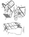
- FIG. 1 the outline of an overhead camshaft four cylinder in-line vehicle engine 1 is illustrated. Such an engine will have three mountings, two at one end of the engine and the third at the other. The illustrated arrangement is intended to prevent the transmission of vibrations from the two mountings at one end of the engine to the vehicle body. One of these mountings is illustrated in Fig. 1.
- the mounting of Fig. 1 comprises a cylindrical rubber block 2 which is identical to a conventional engine mounting.
- the bottom end of the block 2 rests on the vehicle body (not shown) and the top end bears against a spot welded fitting 3 (Fig. 2) flexibly linked to an engine mounted bracket 4.
- the bracket 4 comprises a flexible arm 5, the end of the arm being connected to a rigid lever arm formed by a plate having two flanged edges 6.
- the flanges 6 stiffen the lever arm which with the bracket 4 defines a cantilever supported on the block 2, the cantilever being flexible only in the arm portion 5 of the bracket.
- the block 2 is located approximately three quarters of the way along the cantilever towards the bracket 4.
- the end of the lever arm plate is secured to one end of a tie rod 7, the other end being secured to a beam 8 (Fig. 3) located above the camshaft and outside the engine casing.
- the vertical position of the beam 8 is determined by a cam follower 9 which bears against a four lobed cam 10 on the camshaft 11.
- the cam follower 9 extends through a stabilising and sealing grommet 12 in the engine casing (not shown in Fig. 3).
- a second tie rod extends from the beam 8 to the other mounting (not shown) which is identical to that illustrated.
- the beam 8 oscillates up and down.
- the rod 7, and the cantilever By appropriate design of the cam and the lever system formed by the beam 8, the rod 7, and the cantilever, vibrations resulting from the rotation of the engine can be prevented from reaching the vehicle body.
- the cantilever pivots relative to the fitting 3 and thus although there is some flexing of the cantilever no twisting force (which would result in vibrations) is transmitted into the block 2. If the engine or vehicle body is subjected to shocks, for example as the result of road induced vibrations, these shocks are transmitted almost entirely via the main load transmitting path defined through the block 2 to the bracket 4 in the normal way. A small component of these shocks will be transmitted into the lever system but this will not be sufficient to disrupt operation of the vibration eliminating system.
- the third engine mounting is a standard resilient mounting. If this third mounting is placed near the axis of rocking of the engine the transmission of vibrations through it will be minimised. In typical engines the distance between the third mounting and the axis of rocking is often of the order of 10cm although considerably greater distances can be found. An ideal arrangement is found when the universal joint of the propellor shaft and the third mounting are both as near as possible to the axis of rocking.
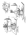
- the illustrated embodiment comprises two flat elastic cantilever plates 13 (only one of which is shown) which are fixed at one end to brackets 14 secured to the engine while the other ends are moved sinusoidally through a simple linkage comprising rods 15 and 16 by a cam 17 fixed to the crankshaft of an engine.
- a stabilising ligament 18 holds a cam follower 19 in position.
- Rubber mountings 20 (only one of which is shown) are in contact with the cantilevers at appropriate distances from the ends fixed to the engine brackets 14. The deflection of the cantilevers is again related to the amplitude of the sinusoidal displacement of the engine so that the compression of the rubber supports is constant corresponding only to the weight and not the vibration of the engine.
- FIG. 5 there is shown in schematic form a third embodiment of the present invention for eliminating the transmission of second order harmonic vibrations from a reciprocating engine 21 to a base 22.
- the engine 21 is supported on the base 22 by a cylindrical rubber body 23, a supporting plate 24, and between the body 23 and the plate 24, two horizontally orientated limbs 25 and 26 of a three limbed flexible interstitial element 27.
- the horizontal limbs 25 and 26 together define a U-shaped spring member, and the free end of the other limb 28 defines a lever arm which extends substantially vertically and contacts a two lobed cam 29.
- the flexible interstitial element 27 is rigid enough to support the static weight of the engine 21, but at the same time is sufficiently flexible to allow the two horizontal limbs 25 and 26 to move towards and away from each other as the engine 21 vibrates and the cam 29 applies a cyclically varying horizontal force to the third limb 28.
- the cam 29 is synchronised to apply an increased horizontal force to the third limb 28 as the second order harmonic component of the inertia force of the engine 21 acts downwards and to apply a reduced horizontal force as the second order harmonic component of the inertia force of the engine 21 acts upwards.
- the limb 28 were stationary, as the inertia force of the engine 21 acted downwards the horizontal legs 25 and 26 would move downwards with it, and as the inertia force of the engine acted upwards they would move upwards with it.
- the application of a cyclically varying horizontal force to the third limb 28 as described above is effective however to exert a force on the lower horizontal limb 26 sufficient to maintain the limb 26 stationary despite the movement of the upper horizontal limb 25. It will be appreciated therefore that as the upper horizontal leg 25 moves with the engine the lower horizontal leg 26 remains stationary and therefore no vibration is transmitted from the engine 21 to its base 22.
- the illustrated arrangement is similar to that of Fig. 5 except that the intersticial element consists of two generally vertical lever arm members 30 linked by a central portion defining a horizontal spring member 31.
- the horizontal member deflects upwards at its central section and follows the engine in its upwards excursion while the sections of the horizontal member resting on mountings 33 remain stationary with respect to the base 34.
- a cam 35 is fixed to the crankshaft inside the crankcase between two adjacent cranks or possibly between a crank and a bearing. As the force on the cam 35 is much smaller than that operating the engine valves, the axial length of this cam is only a fraction of that of the valve cams.
- Two push-rods 36 stabilised by vertical ligaments 37, pass through the walls of the crankcase via flexible grommets and operate vertical members of double L-shaped elements 38. Central portions of the elements 38 rest on standard mountings 39, the upper limbs contacting the push rods 36 and the lower limbs being secured to the engine casing.
- the standard mountings 39 are in contact with a vehicle body 40.
- FIG. 8 there is shown in schematic form a further embodiment of the present invention.
- An engine 41 is supported on a base 42 by a cylindrical rubber mounting 43, against which a supporting plate 44 bears.
- a further supporting plate 45 Secured to the engine 41 is a further supporting plate 45, on which is mounted a backing plate 46 and a flexible compression plate 47 which is acted upon by a two lobed cam 48 connected to the crankshaft of the engine 41.
- the crankshaft axis is indicated by a dashed line.
- Located between the backing plate 46 and the compression plate 47 is the free end of a closed rubber tube 49 which is filled with an incompressible fluid, for example brake fluid.
- the other end of the rubber tube 49 is wrapped around the cylindrical rubber body 43 and the rubber tube 49 is prevented from expanding by a rigid armouring 50 (shown only around that portion of the tube 49 around the resilient cylindrical body 43) except at that portion of its surface in contact with the rubber body 43.
- the expansion of the rubber tube 49 applies radial pressure to the rubber body 43 which results in the axial dimension of the body 43 increasing.
- the force applied to the body 43 by the tube 49 is orthogonal to the force exerted on the body 43 by the engine.
- the body 43 returns to its original dimension. (It should be realised here that the increase in the axial dimension of the body 43 does not involve an axial force or pressure; both changes, the radial and the axial, are caused by the radial pressure alone).
- the change in the axial dimension of the body 43 is quite independent of the static compression of the body 43.
- Fig. 9 The embodiment of Fig. 9 is dependent upon Poisson's type deflection of cylindrical rubber mountings 51 in a similar manner to the embodiment of Fig. 8. However the required radial force is applied not by hydraulic pressure as in Fig. 8 but by an elastic steel hoop 52 which is operated by a cam 53 acting on a pushrod 54. One end of the hoop 52 is fixed so that movements of the other end determine the radial compression of the mounting 51.
- the mounting provides a main load transmitting path and that the force applied to the mounting to prevent the transmission of vibrations is applied externally to the mounting at a point or region spaced from the load transmitting path.
- the mounting can transfer shocks resulting from for example road induced vibrations in the normal way, bypassing the anti-vibration system.
- the forces Wich must be delivered by the anti-vibration system can be relatively small compared with the forces transmitted through the mounting.
- means other than a cam driven by a vibrating system may be provided to synchronise the movement of the mounting with the vibration.
- means other than a cam driven by a vibrating system may be provided to synchronise the movement of the mounting with the vibration.
- electronic, electro-magnetic, and hydraulic devices may be used.
- the present invention is not restricted to use with reciprocating engines, but can be used to eliminate the transmission of vibration from any vibrating system to its support base.
Landscapes
- Engineering & Computer Science (AREA)
- Mechanical Engineering (AREA)
- General Engineering & Computer Science (AREA)
- Chemical & Material Sciences (AREA)
- Combustion & Propulsion (AREA)
- Transportation (AREA)
- Physics & Mathematics (AREA)
- Acoustics & Sound (AREA)
- Aviation & Aerospace Engineering (AREA)
- Vibration Prevention Devices (AREA)
- Arrangement Or Mounting Of Propulsion Units For Vehicles (AREA)
Applications Claiming Priority (2)
| Application Number | Priority Date | Filing Date | Title |
|---|---|---|---|
| GB8211972 | 1982-04-26 | ||
| GB8211972 | 1982-04-26 |
Publications (3)
| Publication Number | Publication Date |
|---|---|
| EP0093530A2 true EP0093530A2 (de) | 1983-11-09 |
| EP0093530A3 EP0093530A3 (en) | 1984-12-12 |
| EP0093530B1 EP0093530B1 (de) | 1987-06-10 |
Family
ID=10529945
Family Applications (1)
| Application Number | Title | Priority Date | Filing Date |
|---|---|---|---|
| EP83302168A Expired EP0093530B1 (de) | 1982-04-26 | 1983-04-18 | Lagerung für ein vibrierendes System |
Country Status (5)
| Country | Link |
|---|---|
| US (1) | US4515122A (de) |
| EP (1) | EP0093530B1 (de) |
| JP (1) | JPS591836A (de) |
| DE (1) | DE3371972D1 (de) |
| GB (1) | GB2121509B (de) |
Families Citing this family (1)
| Publication number | Priority date | Publication date | Assignee | Title |
|---|---|---|---|---|
| DE4002600A1 (de) * | 1990-01-30 | 1991-08-01 | Audi Ag | Lagerung fuer das antriebsaggregat in einem kraftfahrzeug |
Family Cites Families (21)
| Publication number | Priority date | Publication date | Assignee | Title |
|---|---|---|---|---|
| GB282583A (en) * | 1927-04-20 | 1927-12-29 | Gen Motors Res Corp | Improvements in mountings for engine casings and the like |
| US2108515A (en) * | 1928-10-22 | 1938-02-15 | Gen Motors Corp | Motor mounting |
| US1929104A (en) * | 1929-10-18 | 1933-10-03 | Gen Motors Res Corp | Mounting for v-8 engines |
| US1949064A (en) * | 1933-04-19 | 1934-02-27 | Herbert J Nathan | Power plant mounting |
| DE742776C (de) * | 1937-07-21 | 1943-12-10 | Bolinder Munktell | Massenausgleicheinrichtung |
| US3037574A (en) * | 1952-09-17 | 1962-06-05 | Gyreacta Transmission Ltd | Vehicle driving systems |
| GB1020851A (en) * | 1963-01-11 | 1966-02-23 | Rover Co Ltd | Suspension of machinery and other bodies |
| GB1370682A (en) * | 1972-02-15 | 1974-10-16 | Husqvarna Vapenfabriks Ab | Mountings for reciprocating piston machines |
| JPS52147329U (de) * | 1976-05-06 | 1977-11-08 | ||
| FR2364373A1 (fr) * | 1976-09-09 | 1978-04-07 | Peugeot | Dispositif de suspension pour machine tournante |
| DE2861850D1 (en) * | 1977-08-30 | 1982-07-08 | James Prince Love | Improvements in or relating to the reduction of vibration from mechanisms |
| DE2825927A1 (de) * | 1978-06-14 | 1980-01-03 | Volkswagenwerk Ag | Schallisolierend gekapselte brennkraftmaschine |
| AT377331B (de) * | 1977-11-23 | 1985-03-11 | List Hans | Geraeuschgedaemmte brennkraftmaschine |
| AT350855B (de) * | 1977-11-23 | 1979-06-25 | List Hans | Brennkraftmaschine |
| JPS5629010A (en) * | 1979-08-17 | 1981-03-23 | Nissan Motor Co Ltd | Lubricator for internal combustion engine |
| JPS5643028A (en) * | 1979-09-18 | 1981-04-21 | Nissan Motor Co Ltd | Low noise vehicle |
| JPS56145633U (de) * | 1980-04-02 | 1981-11-02 | ||
| AT377332B (de) * | 1980-05-28 | 1985-03-11 | List Hans | Brennkraftmaschine |
| FR2507976A1 (fr) * | 1981-06-23 | 1982-12-24 | Peugeot | Dispositif de suspension pour groupe moto-propulseur de vehicule automobile |
| JPS5853935U (ja) * | 1981-10-09 | 1983-04-12 | 株式会社ブリヂストン | 防振ゴム |
| US4531484A (en) * | 1981-11-20 | 1985-07-30 | Nissan Motor Co., Ltd. | Vibration responsive mounting arrangement for automotive engine or the like |
-
1983
- 1983-04-18 EP EP83302168A patent/EP0093530B1/de not_active Expired
- 1983-04-18 DE DE8383302168T patent/DE3371972D1/de not_active Expired
- 1983-04-18 GB GB08310428A patent/GB2121509B/en not_active Expired
- 1983-04-20 US US06/486,943 patent/US4515122A/en not_active Expired - Fee Related
- 1983-04-25 JP JP58071555A patent/JPS591836A/ja active Granted
Also Published As
| Publication number | Publication date |
|---|---|
| JPS591836A (ja) | 1984-01-07 |
| DE3371972D1 (en) | 1987-07-16 |
| JPH0345257B2 (de) | 1991-07-10 |
| GB2121509A (en) | 1983-12-21 |
| US4515122A (en) | 1985-05-07 |
| EP0093530A3 (en) | 1984-12-12 |
| GB2121509B (en) | 1986-07-23 |
| EP0093530B1 (de) | 1987-06-10 |
| GB8310428D0 (en) | 1983-05-25 |
Similar Documents
| Publication | Publication Date | Title |
|---|---|---|
| US4154206A (en) | Suspension device for a rotating machine lacking balance | |
| US3668939A (en) | Plane omnidirectional absorber | |
| US4781363A (en) | Vibration isolator particularly of the antiresonance force type | |
| US6029541A (en) | Reciprocating machine with neutralization of free inertial forces | |
| EP0081085A1 (de) | Auf Vibrationen reagierende Einbauvorrichtung für einen Fahrzeugmotor | |
| US5235909A (en) | Device for damping bending vibrations in a cylinder of a rotary printing press | |
| EP0227277A1 (de) | Vorrichtung aus hin- und hergehenden Ausgleichsmassen für eine Kolben-Brennkraftmaschine | |
| US5025600A (en) | Isolation floor system for earthquake | |
| US4515122A (en) | Mounting for a vibrating system | |
| US3808983A (en) | Vibration suppressing table | |
| GB2265669A (en) | Reciprocating compressor dynamic balancer | |
| RU2215925C1 (ru) | Устройство для гашения колебаний трубопровода | |
| JP2000027934A (ja) | 能動型制振器 | |
| SU1024780A1 (ru) | Устройство дл испытани изделий на вибрацию | |
| SE8202031L (sv) | Vibrationsanordning | |
| RU2008390C1 (ru) | Валец катка | |
| KR20160114740A (ko) | 피스톤 엔진의 진동 감쇠 구조체 및 진동 감쇠 방법과 피스톤 엔진 | |
| RU2086829C1 (ru) | Виброзащитный подвес | |
| SU1209925A1 (ru) | Устройство дл гашени вибраций поршневого компрессора | |
| SU1455253A1 (ru) | Стенд дл испытани шатунов на усталость | |
| SU1030494A1 (ru) | Устройство дл срезки сваи | |
| SU937820A1 (ru) | Амортизатор | |
| KR20020066730A (ko) | 마찰식 완충기 | |
| RU2059558C1 (ru) | Виброподъемник | |
| SU1472720A1 (ru) | Устройство св зи подвижных дисков фрикционного амортизатора с колеблющимс элементом |
Legal Events
| Date | Code | Title | Description |
|---|---|---|---|
| PUAI | Public reference made under article 153(3) epc to a published international application that has entered the european phase |
Free format text: ORIGINAL CODE: 0009012 |
|
| AK | Designated contracting states |
Designated state(s): DE FR GB IT SE |
|
| PUAL | Search report despatched |
Free format text: ORIGINAL CODE: 0009013 |
|
| AK | Designated contracting states |
Designated state(s): DE FR GB IT SE |
|
| 17P | Request for examination filed |
Effective date: 19850222 |
|
| 17Q | First examination report despatched |
Effective date: 19860411 |
|
| GRAA | (expected) grant |
Free format text: ORIGINAL CODE: 0009210 |
|
| ITF | It: translation for a ep patent filed | ||
| AK | Designated contracting states |
Kind code of ref document: B1 Designated state(s): DE FR IT SE |
|
| REF | Corresponds to: |
Ref document number: 3371972 Country of ref document: DE Date of ref document: 19870716 |
|
| ET | Fr: translation filed | ||
| PLBE | No opposition filed within time limit |
Free format text: ORIGINAL CODE: 0009261 |
|
| STAA | Information on the status of an ep patent application or granted ep patent |
Free format text: STATUS: NO OPPOSITION FILED WITHIN TIME LIMIT |
|
| 26N | No opposition filed | ||
| ITPR | It: changes in ownership of a european patent |
Owner name: CESSIONE;BRITISH TECHNOLOGY GROUP LIMITED |
|
| REG | Reference to a national code |
Ref country code: FR Ref legal event code: TP |
|
| ITTA | It: last paid annual fee | ||
| PGFP | Annual fee paid to national office [announced via postgrant information from national office to epo] |
Ref country code: SE Payment date: 19940330 Year of fee payment: 12 |
|
| PGFP | Annual fee paid to national office [announced via postgrant information from national office to epo] |
Ref country code: FR Payment date: 19940331 Year of fee payment: 12 |
|
| PGFP | Annual fee paid to national office [announced via postgrant information from national office to epo] |
Ref country code: DE Payment date: 19940620 Year of fee payment: 12 |
|
| EAL | Se: european patent in force in sweden |
Ref document number: 83302168.6 |
|
| PG25 | Lapsed in a contracting state [announced via postgrant information from national office to epo] |
Ref country code: SE Effective date: 19950419 |
|
| PG25 | Lapsed in a contracting state [announced via postgrant information from national office to epo] |
Ref country code: FR Effective date: 19951229 |
|
| PG25 | Lapsed in a contracting state [announced via postgrant information from national office to epo] |
Ref country code: DE Effective date: 19960103 |
|
| EUG | Se: european patent has lapsed |
Ref document number: 83302168.6 |
|
| REG | Reference to a national code |
Ref country code: FR Ref legal event code: ST |