EP0092717A1 - Ultraschall-Applikator - Google Patents
Ultraschall-Applikator Download PDFInfo
- Publication number
- EP0092717A1 EP0092717A1 EP83103447A EP83103447A EP0092717A1 EP 0092717 A1 EP0092717 A1 EP 0092717A1 EP 83103447 A EP83103447 A EP 83103447A EP 83103447 A EP83103447 A EP 83103447A EP 0092717 A1 EP0092717 A1 EP 0092717A1
- Authority
- EP
- European Patent Office
- Prior art keywords
- handle
- ultrasound
- ultrasonic
- head housing
- application surface
- Prior art date
- Legal status (The legal status is an assumption and is not a legal conclusion. Google has not performed a legal analysis and makes no representation as to the accuracy of the status listed.)
- Granted
Links
Images

Classifications
-
- A—HUMAN NECESSITIES
- A61—MEDICAL OR VETERINARY SCIENCE; HYGIENE
- A61B—DIAGNOSIS; SURGERY; IDENTIFICATION
- A61B8/00—Diagnosis using ultrasonic, sonic or infrasonic waves
- A61B8/42—Details of probe positioning or probe attachment to the patient
- A61B8/4209—Details of probe positioning or probe attachment to the patient by using holders, e.g. positioning frames
- A61B8/4218—Details of probe positioning or probe attachment to the patient by using holders, e.g. positioning frames characterised by articulated arms
-
- A—HUMAN NECESSITIES
- A61—MEDICAL OR VETERINARY SCIENCE; HYGIENE
- A61B—DIAGNOSIS; SURGERY; IDENTIFICATION
- A61B8/00—Diagnosis using ultrasonic, sonic or infrasonic waves
- A61B8/12—Diagnosis using ultrasonic, sonic or infrasonic waves in body cavities or body tracts, e.g. by using catheters
-
- A—HUMAN NECESSITIES
- A61—MEDICAL OR VETERINARY SCIENCE; HYGIENE
- A61B—DIAGNOSIS; SURGERY; IDENTIFICATION
- A61B8/00—Diagnosis using ultrasonic, sonic or infrasonic waves
- A61B8/42—Details of probe positioning or probe attachment to the patient
-
- G—PHYSICS
- G10—MUSICAL INSTRUMENTS; ACOUSTICS
- G10K—SOUND-PRODUCING DEVICES; METHODS OR DEVICES FOR PROTECTING AGAINST, OR FOR DAMPING, NOISE OR OTHER ACOUSTIC WAVES IN GENERAL; ACOUSTICS NOT OTHERWISE PROVIDED FOR
- G10K11/00—Methods or devices for transmitting, conducting or directing sound in general; Methods or devices for protecting against, or for damping, noise or other acoustic waves in general
- G10K11/004—Mounting transducers, e.g. provided with mechanical moving or orienting device
Definitions
- the invention relates to an ultrasound applicator for ultrasound scanning, in particular of internal organs or the like, with an ultrasound head, which comprises a number of ultrasound elements, which are enclosed by an elongated, rigid housing, one of which is concerned
- Application surface that can be placed on the organ has an elongated, rigid handle and a retaining connection between the ultrasound head and the handle.
- Ultrasound applicators of this type have already been proposed, but all of them are designed only for scanning internal organs from the intact body surface. However, it would be desirable to have an ultrasound applicator that can also be used intraoperatively.
- an endoscope which consists of an eyepiece, a flexible tube, a controllably bendable intermediate piece and a cylindrical end piece, the flexible hose having a light guide and control lines and the end piece containing an ultrasound head.
- Such an endoscope is not very suitable for intra-operative treatment because it can hardly be sterilized sufficiently due to the sensitive optics.
- the bendable intermediate piece only allows work with relatively small bending angles.
- An endoscope is also known from European patent application 00 39 045, which carries two ultrasound heads on a manipulable end piece.
- the manipulation angle of the end piece is also relatively small in this endoscope. It should only be a few degrees. Because of the manipulation mechanism of not to be neglected extent, which is housed inside, the endoscope can only be used in surgical fields with a minimum extent.
- German utility model 69 42 159 a medical ultrasound test probe is known which comprises a handle, a flexible hose connection and at the end of which an ultrasound transducer. Angling the ultrasound transducer directly at the end of the tube is not possible here, so that the examination of internal organs during an operation is also limited.
- the object of the invention is to provide an ultrasound applicator which is suitable for intra-operative use in various types of applications, which is easy to handle and does not require a particularly large access in the operating field.
- the holding connection is a swivel or rotary connection which connects the one end of the ultrasound head housing directly to the one end of the handle in a pivotable or rotatable manner, the inclination of the ultrasound head housing with respect to the handle from on the hand gripping hand is adjustable.
- the pivotable or rotatable ultrasound head can be easily moved by hand into any one Bring application position.
- the ultrasound applicator according to the invention is therefore particularly well suited for use in operations.
- the ultrasound head can be angled practically immediately behind the handle.
- the application area is fully usable, ie examinations in great depth are possible even in a small operating field.
- FIG. 1 shows an ultrasound head which is designed as an ultrasound array 1 and comprises an elongated, rigid array housing 2 with an application surface 3.
- the ultrasound array 2 has a plurality of transducer elements 4 on the application surface 3, as shown in the enlarged detail, which are enclosed by the housing 2 and which are in the present embodiment example are finely divided.
- Several of these finely divided transducer elements 4, in the present case a total of, for example, four transducer elements, are electrically connected to form a group 5 (of, for example, a total of 48 groups).
- Contact lugs 6 of a contact comb are used for group contacting. 7 with a support body: for the ultrasound transducer elements 4.
- the carrier body 7, in which the contact tabs 6 are embedded, consists, for example, of epoxy resin with oxidized tungsten powder introduced.
- 8 denotes an adaptation layer for the converter elements.
- the adaptation layer can consist of epoxy resin. The basic principle of the fine division of converter elements is described in more detail, for example, in US Pat. No. 4,3 05,014.
- the application surface 3 can have a length of 3 centimeters, for example. The length depends on the type of possible applications.
- the ultrasound array 1 on the array housing 2, and practically directly at the end 9, has a swivel joint 10, by means of which the ultrasound array 1 is pivoted or pivoted on a handle 11 with predefinable friction.
- the handle 11 is relatively thin. For example, it can have a diameter of 10 to 12 mm.
- the array 1 is adjustable in a welding range of preferably> + 90 ° with respect to the longitudinal axis: of the handle 11. The adjustment success' manually by acting on the handle 11 of the surgeon's hand. Further details on the pivotability are shown in FIG. 2, which also shows that the signal connection cable 12 of the ultrasound array 1 is guided inside the hollowed-out handle 11.
- the signal connection cable 12 is mounted in such a way that it can follow the ultrasound array 1 practically without draft in any swivel or rotational position.
- the macaw; the handle 11, the hinge 10 and the cable 12 are relatively easy to sterilize.
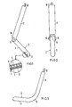
- FIG. 3 shows an embodiment in which the ultrasound array 1 and the handle 11 are flexibly connected at the coupling point 13.
- the handle 11 only at the bending point 13 or as a whole part made of flexible material, e.g. flexible plastic.
- the ultrasound head 1 can also be at least partially bendable.
- the embodiment according to FIGS. 1 and 2 has the advantage that organs in deep positions can be reached even in a small operating field.
- the ultrasound applicators of FIGS. 1 to 3 are particularly suitable for intra-operative use, although transcutaneous use is also possible.
- FIG. 4 The possibility of intra-operative use is shown in FIG. 4 using the example of a kidney examination.
- a kidney exposed by the operation is designated 14.
- the ultrasound array 1 lies with the application surface 3 in the examination position A e.g. on the front wall of the kidney 14.
- the ultrasound array 1 with its application surface 3 lies on the rear wall of the kidney 14. It is clear from this that the elongated ultrasound head housing 2 can be pivoted from an inclination angle greater than 0 ° to an inclination angle less than 0 °.
- the angle of inclination is the angle lying between the application surface 3 and the longitudinal axis of the handle 11.
- FIG. 5 shows the intra-operative application of the invention to a liver 15.
- the ultrasound array 1 is gripped by hand 16 in the manner shown and, after being inserted below the open diaphragm 17, by swiveling relative to the handle 11 into a suitable application position brought to the liver 15. It goes without saying that such examinations can be carried out not only on a kidney 14 or liver 15, but on any other internal organ or any other internal part of the body.
Abstract
Description
- Die Erfindung bezieht sich auf einen Ultraschall-Applikator für die Ultraschallabtastung, insbesondere von körperinternen Organen od.dgl., mit einem Ultraschallkopf, der eine Anzahl von Ultraschall-Elementen umfaßt, die von einem länglichen, starren Gehäuse umschlossen sind, das eine auf das betreffende Organ auflegbare Applikationsfläche besitzt, mit einem länglichen, starren Handgriff und mit einer Halteverbindung zwischen dem Ultraschallkopf und dem Handgriff.
- Es sind bereits Ultraschall-Applikatoren dieser Art vorgeschlagen worden, die jedoch alle nur zur Abtastung von körperinternen Organen von der unversehrten Körperoberfläche her ausgebildet sind. Wünschenswert wäre jedoch ein Ultraschall-Applikator, der auch intraoperativ eingesetzt werden kann.
- Aus der DE-OS 29 50 203 ist bereits ein Endoskop bekannt, das aus einem Okular, einem flexiblen Schlauch, einem steuerbar biegbaren Zwischenstück und einem zylinderförmigen Endstück besteht, wobei der flexible Schlauch einen Lichtleiter und Steuerleitungen und wobei das Endstück einen Ultraschallkopf enthält. Ein solches Endoskop ist für eine intra-operative Behandlung wenig geeignet, da es wegen der empfindlichen Optik kaum ausreichend sterilisiert werden kann. Außerdem gestattet das biegbare Zwischenstück nur ein Arbeiten mit verhältnismäßig geringen Biegewinkeln. Darüber hinaus ist es schwierig, bei begrenztem Operationsfeld das zylinderförmige Endstück so zu plazieren, daß der Ultraschallkopf - vom Operationsfeld aus gesehen - unter dem zu untersuchenden Organ liegt. Die Anwendungsmöglichkeiten sind also recht beschränkt.
- Aus der europäischen Patentanmeldung 00 39 045 ist ebenfalls ein Endoskop bekannt, das an einem manipulierbaren Endstück zwei Ultraschallköpfe trägt. Auch bei diesem Endoskop ist der Manipulationswinkel des Endstücks verhältnismäßig klein. Er dürfte nur wenige Grad betragen. Wegen des im Innern untergebrachten Manipulationsmechanismus von nicht zu vernachlässigender Ausdehnung kann das Endoskop nur in Operationsfeldern von einer Mindestausdehnung ab verwendet werden.
- Aus dem deutschen Gebrauchsmuster 69 42 159 ist schließlich eine medizinische Ultraschall-Prüfsonde bekannt, die einen Handgriff, eine biegsame Schlauchverbindung und an deren Ende einen Ultraschall-Wandler umfaßt. Ein Abwinkeln des Ultraschall-Wandlers unmittelbar am Ende des Schlauches ist hier nicht möglich, so daß der Untersuchung körperinterner Organe bei einer Operation ebenfalls Grenzen gesetzt sind.
- Aufgabe der Erfindung ist es, einen Ultraschall-Applikator zu schaffen, der für den intra-operativen Einsatz bei verschiedenartigen Anwendungsfällen geeignet ist, der leicht handhabbar ist und keinen besonders großen Zugang im Operationsfeld erfordert.
- Die Aufgabe wird erfindungsgemäß dadurch gelöst, daß die Halteverbindung eine Schwenk- oder Drehverbindung ist, die das eine Ende des Ultraschallkopf-Gehäuses unmittelbar mit dem einen Ende des Handgriffs schwenk-oder drehbar verbindet, wobei die Neigung des Ultraschallkopf-Gehäuses bezüglich des Handgriffs von der am Handgriff angreifenden Hand einstellbar ist.
- Der schwenk- oder drehbar gehalterte Ultraschallkopf läßt sich in einfacher Weise von Hand in jede beliebige Applikationslage bringen. Bezüglich des zu untersuchenden körperinternen Organes bedeutet dies, daß der Ultraschall-Applikator beliebig rück-, vorder- oder seitenwandig an das abzustastende Organ angelegt werden kann. Der erfindungsgemäße Ultraschall-Applikator eignet sich also besonders gut zum Einsatz bei Operationen. Der Ultraschallkopf läßt sich praktisch unmittelbar hinter dem Handgriff abwinkeln. Die Applikationsfläche ist voll ausnutzbar, d.h. es sind Untersuchungen in großer Tiefe auch bei kleinem Operationsfeld möglich.
- Weitere Vorteile und Einzelheiten der Erfindung ergeben sich aus der nachfolgenden Beschreibung zweier Ausführungsbeispiele anhand der Zeichnung und in Verbindung mit den Unteransprüchen.
- Es zeigen:
- Figur 1 einen Ultraschall-Applikator gemäß der Erfindung in Seitenansicht,
- Figur 2 denselben Ultraschall-Applikator in Vorderansicht,
- Figur 3 einen Ultraschall-Applikator mit Biegeteil in Seitenansicht,
- Figur 4 Applikationsmöglichkeiten für einen Ultraschall-Applikator gemäß der Erfindung bei intra-operativem Einsatz an einem Körperorgan wie z.B. einer Niere,
- Figur 5 weitere Applikationsmöglichkeiten an einem Organ wie z.B. der Leber.
- Figur 1 zeigt einen Ultraschallkopf, der als Ultraschall-Array 1 ausgebildet ist und ein längliches, starres Array-Gehäuse 2 mit einer Applikationsfläche 3 umfaßt. Das Ultraschall-Array 2 besitzt dabei an der Applikationsfläche 3, wie in der Ausschnittsvergrößerung dargestellt ist, eine Vielzahl von Wandlerelementen 4, die vom Gehäuse 2 umschlossen und die im vorliegenden Ausführungsbeispiel feingeteilt sind. Jeweils mehrere dieser feingeteilten Wandlerelemente 4, im vorliegenden Fall insgesamt z.B. vier Wandlerelemente, sind elektrisch zu einer Gruppe 5 (von z.B. insgesamt 48 Gruppen) zusammenkontaktiert. Zur Gruppenkontaktierung dienen Kontaktfahnen 6 eines Kontaktkammes. Mit 7 ist ein Trägerkörpe: für die Ultraschall-Wandlerelemente 4 bezeichnet. Der Trägerkörper 7, in den die Kontaktfahnen 6 eingebettet sind, besteht beispielsweise aus Epoxydharz mit eingebrachtem oxidiertem Wolframpulver. Mit 8 ist eine Anpassungsschicht für die Wandlerelemente bezeichnet. Die Anpassungsschicht kann aus Epoxydharz bestehen. Das Grundprinzip der Feinteilung von Wandlerelementen ist z.B. in der US-PS 43 05 014 näher beschrieben. Die Applikationsfläche 3 kann z.B. eine Länge von 3 Zentimetern besitzen. Die Länge richtet sich nach der Art der in Betracht kommenden Anwendungsfälle.
- Gemäß Figur 1 weist das Ultraschall-Array 1 am Array-Gehäuse 2, und zwar praktisch unmittelbar am Ende 9, ein Drehgelenk 10 auf, mittels dessen das Ultraschall-Array 1 an einem Handgriff 11 mit vorgebbarer Reibung dreh- oder schwenkbar angelenkt ist. Der Handgriff 11 ist verhältnismäßig dünn. Er kann z.B. einen Durchmess von 10 bis 12 mm haben. Das Array 1 ist in einem Schwe bereich von vorzugsweise>+ 90° bezüglich der Längsach: des Handgriffs 11 verstellbar. Die Verstellung erfolg' manuell von der am Handgriff 11 angreifenden Hand des Operateurs. Nähere Details zur Schwenkbarkeit sind de Figur 2 entnehmbar, in der auch gezeigt ist, daß das Signalanschlußkabel 12 des Ultraschall-Arrays 1 im Innern des ausgehöhlten Handgriffs 11 geführt ist. Ds Signalanschlußkabel 12 ist dabei so gelagert, daß es dem Ultraschall-Array 1 praktisch zugfrei in jede beliebige Schwenk- oder Drehlage folgen kann. Das Arra; der Handgriff 11, das Drehgelenk 10 und das Kabel 12 sind verhältnismäßig einfach zu sterilisieren.
- Figur 3 zeigt eine Ausführungsform, bei der das Ultraschall-Array 1 und der Handgriff 11 an der Ankoppelstelle 13 biegsam verbunden sind. Dazu kann z.B. der Handgriff 11 lediglich an der Biegestelle 13 oder als ganzes Teil aus biegsamem Material, z.B. biegsamem Kunststoff, hergestellt sein. Gegebenenfalls kann auch der Ultraschallkopf 1 wenigstens teilweise biegbar sein. Die Ausführung nach Figur 1 und 2 hat aber demgegenüber den Vorteil, daß auch bei kleinem Operationsfeld Organe in tiefen Lagen erreicht werden können.
- Die Ultraschall-Applikatoren der Figuren 1 bis 3 eignen sich insbesondere für den intra-operativen Einsatz, obgleich auch ein transkutaner Einsatz möglich ist.
- Die Möglichkeit des intra-operativen Einsatzes ist am Beispiel einer Nierenuntersuchung in Figur 4 dargestellt. Hier ist eine durch die Operation freigelegte Niere mit 14 bezeichnet. Das Ultraschall-Array 1 liegt mit der Applikationsfläche 3 in der Untersuchungsposition A z.B. auf der Vorderwand der Niere 14 an. In der Untersuchungsposition B liegt das Ultraschall-Array 1 mit seiner Applikationsfläche 3 hingegen an der Rückwand der Niere 14. Hieraus wird deutlich, daß das längliche Ultraschallkopf-Gehäuse 2 von einen Neigungswinkel größer 0° in einen Neigungswinkel kleiner 0° geschwenkt werden kann. Der Neigungswinkel ist dabei der zwischen der Applikationsfläche 3 und der Längsachse des Handgriffs 11 liegende Winkel.
- Die Figur 5 zeigt die intra-operative Anwendung der Erfindung an einer Leber 15. Das Ultraschall-Array 1 wird dazu in der dargestellten Weise mit der Hand 16 umfaßt und nach Einschieben unterhalb des geöffneten Zwerchfells 17 durch Schwenken gegenüber dem Handgriff 11 in eine geeignete Applikationsposition an der Leber 15 gebracht. Es ist selbstverständlich, daß derartige Untersuchungen nicht nur an einer Niere 14 oder Leber 15, sondern an jedem beliebigen anderen körperinternen Organ oder einem sonstigen inneren Körperteil vorgenommen werden können.
Claims (3)
Priority Applications (1)
| Application Number | Priority Date | Filing Date | Title |
|---|---|---|---|
| AT83103447T ATE16864T1 (de) | 1982-04-26 | 1983-04-08 | Ultraschall-applikator. |
Applications Claiming Priority (2)
| Application Number | Priority Date | Filing Date | Title |
|---|---|---|---|
| DE19823215539 DE3215539A1 (de) | 1982-04-26 | 1982-04-26 | Ultraschall-applikator |
| DE3215539 | 1982-04-26 |
Publications (2)
| Publication Number | Publication Date |
|---|---|
| EP0092717A1 true EP0092717A1 (de) | 1983-11-02 |
| EP0092717B1 EP0092717B1 (de) | 1985-12-04 |
Family
ID=6161985
Family Applications (1)
| Application Number | Title | Priority Date | Filing Date |
|---|---|---|---|
| EP83103447A Expired EP0092717B1 (de) | 1982-04-26 | 1983-04-08 | Ultraschall-Applikator |
Country Status (4)
| Country | Link |
|---|---|
| EP (1) | EP0092717B1 (de) |
| JP (1) | JPS58190430A (de) |
| AT (1) | ATE16864T1 (de) |
| DE (2) | DE3215539A1 (de) |
Cited By (1)
| Publication number | Priority date | Publication date | Assignee | Title |
|---|---|---|---|---|
| EP0780088A1 (de) * | 1995-12-21 | 1997-06-25 | Hewlett-Packard Company | Fingerhalterung für einen rotierenden Ultraschallwandler |
Citations (6)
| Publication number | Priority date | Publication date | Assignee | Title |
|---|---|---|---|---|
| DE6942159U (de) * | 1969-10-29 | 1970-03-12 | J U H Krautkraemer Ges Fuer El | Ultraschall-pruefsonde, insbesondere zur anwendung in der medizinischen diagnostik |
| US4135826A (en) * | 1977-04-11 | 1979-01-23 | Holm Harold K | Vibrators |
| DE2950203A1 (de) * | 1978-12-15 | 1980-06-19 | Olympus Optical Co | Endoskop |
| FR2450596A1 (fr) * | 1979-03-06 | 1980-10-03 | Radiologie Cie Gle | Echographe a ultrasons par balayage manuel et electronique |
| EP0039045A1 (de) * | 1980-04-28 | 1981-11-04 | Olympus Optical Co., Ltd. | Endoskop mit Ultraschall-Diagnosegerät |
| DE3121512A1 (de) * | 1981-05-29 | 1982-12-23 | SRI International, 94025 Menlo Park, Calif. | Endoskopische sonde, einichtung und zugehoeriges verfahren |
-
1982
- 1982-04-26 DE DE19823215539 patent/DE3215539A1/de not_active Withdrawn
-
1983
- 1983-04-08 AT AT83103447T patent/ATE16864T1/de not_active IP Right Cessation
- 1983-04-08 DE DE8383103447T patent/DE3361387D1/de not_active Expired
- 1983-04-08 EP EP83103447A patent/EP0092717B1/de not_active Expired
- 1983-04-21 JP JP58070837A patent/JPS58190430A/ja active Pending
Patent Citations (6)
| Publication number | Priority date | Publication date | Assignee | Title |
|---|---|---|---|---|
| DE6942159U (de) * | 1969-10-29 | 1970-03-12 | J U H Krautkraemer Ges Fuer El | Ultraschall-pruefsonde, insbesondere zur anwendung in der medizinischen diagnostik |
| US4135826A (en) * | 1977-04-11 | 1979-01-23 | Holm Harold K | Vibrators |
| DE2950203A1 (de) * | 1978-12-15 | 1980-06-19 | Olympus Optical Co | Endoskop |
| FR2450596A1 (fr) * | 1979-03-06 | 1980-10-03 | Radiologie Cie Gle | Echographe a ultrasons par balayage manuel et electronique |
| EP0039045A1 (de) * | 1980-04-28 | 1981-11-04 | Olympus Optical Co., Ltd. | Endoskop mit Ultraschall-Diagnosegerät |
| DE3121512A1 (de) * | 1981-05-29 | 1982-12-23 | SRI International, 94025 Menlo Park, Calif. | Endoskopische sonde, einichtung und zugehoeriges verfahren |
Cited By (1)
| Publication number | Priority date | Publication date | Assignee | Title |
|---|---|---|---|---|
| EP0780088A1 (de) * | 1995-12-21 | 1997-06-25 | Hewlett-Packard Company | Fingerhalterung für einen rotierenden Ultraschallwandler |
Also Published As
| Publication number | Publication date |
|---|---|
| DE3215539A1 (de) | 1983-10-27 |
| DE3361387D1 (en) | 1986-01-16 |
| JPS58190430A (ja) | 1983-11-07 |
| EP0092717B1 (de) | 1985-12-04 |
| ATE16864T1 (de) | 1985-12-15 |
Similar Documents
| Publication | Publication Date | Title |
|---|---|---|
| EP0095075A1 (de) | Ultraschall-Applikator | |
| DE3722943C2 (de) | ||
| DE3709706C2 (de) | ||
| DE69433198T2 (de) | Ultraschall transösophagische Sonde zur Bilderzeugung und Diagnose durch Mehrfachflächenabtastung | |
| DE60205102T2 (de) | Biopsiezange mit transparenter äusserer hülle | |
| DE3510553A1 (de) | Ultraschallsonde | |
| DE2636510C3 (de) | Endoskop, insbesondere Rektoskop, mit lösbarem, lichtleitendem Tubus | |
| DE2950203C2 (de) | Endoskop | |
| DE2809645C2 (de) | ||
| DE19962209B4 (de) | Spitze für ein Ultraschallendoskop | |
| DE69738274T2 (de) | Bewegliche Empfangs- und Sendespulen für ein Ortsbestimmungssystem | |
| DE3244667A1 (de) | Ultraschall-applikator fuer die biopsie | |
| WO1996014800A1 (de) | Deflektierbare nadel | |
| DE19756910A1 (de) | Katheter | |
| DE4417637A1 (de) | Instrument zur perkutanen Behandlung von Gewebeteilen | |
| EP0631758A1 (de) | Implantierbare Messsonde zum Messen der Fliessgeschwindigkeit des Blutes bei Menschen und Tieren | |
| DE69634980T2 (de) | Ultraschall gestütztes biopsiegerät | |
| DE4223897C2 (de) | Rohrförmiger Transportarm | |
| DE3810289A1 (de) | Stiftartige ultraschallsonde mit fingergriff-adapter | |
| DE2937161A1 (de) | Traeger fuer einen wandler zum aussenden und/oder empfangen von ultraschallsignalen in einem bestimmten winkelsektor | |
| DE2826828C2 (de) | ||
| EP0092717B1 (de) | Ultraschall-Applikator | |
| EP0589082B1 (de) | Intrakavitäre Ultraschallsonde | |
| DE3207255C2 (de) | Handgeführter Ultraschall-Applikator | |
| DE112016005463T5 (de) | Handgehaltenes instrument für endoskopische chirurgie |
Legal Events
| Date | Code | Title | Description |
|---|---|---|---|
| PUAI | Public reference made under article 153(3) epc to a published international application that has entered the european phase |
Free format text: ORIGINAL CODE: 0009012 |
|
| AK | Designated contracting states |
Designated state(s): AT CH DE FR GB LI |
|
| 17P | Request for examination filed |
Effective date: 19831213 |
|
| GRAA | (expected) grant |
Free format text: ORIGINAL CODE: 0009210 |
|
| AK | Designated contracting states |
Designated state(s): AT CH DE FR GB LI |
|
| REF | Corresponds to: |
Ref document number: 16864 Country of ref document: AT Date of ref document: 19851215 Kind code of ref document: T |
|
| REF | Corresponds to: |
Ref document number: 3361387 Country of ref document: DE Date of ref document: 19860116 |
|
| ET | Fr: translation filed | ||
| PG25 | Lapsed in a contracting state [announced via postgrant information from national office to epo] |
Ref country code: AT Effective date: 19860408 |
|
| PG25 | Lapsed in a contracting state [announced via postgrant information from national office to epo] |
Ref country code: LI Effective date: 19860430 Ref country code: CH Effective date: 19860430 |
|
| PLBE | No opposition filed within time limit |
Free format text: ORIGINAL CODE: 0009261 |
|
| STAA | Information on the status of an ep patent application or granted ep patent |
Free format text: STATUS: NO OPPOSITION FILED WITHIN TIME LIMIT |
|
| 26N | No opposition filed | ||
| PG25 | Lapsed in a contracting state [announced via postgrant information from national office to epo] |
Ref country code: FR Free format text: LAPSE BECAUSE OF NON-PAYMENT OF DUE FEES Effective date: 19861231 |
|
| REG | Reference to a national code |
Ref country code: CH Ref legal event code: PL |
|
| REG | Reference to a national code |
Ref country code: FR Ref legal event code: ST |
|
| GBPC | Gb: european patent ceased through non-payment of renewal fee | ||
| PG25 | Lapsed in a contracting state [announced via postgrant information from national office to epo] |
Ref country code: DE Effective date: 19880101 |
|
| PG25 | Lapsed in a contracting state [announced via postgrant information from national office to epo] |
Ref country code: GB Effective date: 19881122 |