EP0091752A1 - Wasser-Einspritzsystem für Brennkraftmaschine - Google Patents
Wasser-Einspritzsystem für Brennkraftmaschine Download PDFInfo
- Publication number
- EP0091752A1 EP0091752A1 EP83301729A EP83301729A EP0091752A1 EP 0091752 A1 EP0091752 A1 EP 0091752A1 EP 83301729 A EP83301729 A EP 83301729A EP 83301729 A EP83301729 A EP 83301729A EP 0091752 A1 EP0091752 A1 EP 0091752A1
- Authority
- EP
- European Patent Office
- Prior art keywords
- pressure
- pump
- fluid
- nozzle
- flow path
- Prior art date
- Legal status (The legal status is an assumption and is not a legal conclusion. Google has not performed a legal analysis and makes no representation as to the accuracy of the status listed.)
- Granted
Links
Images


Classifications
-
- F—MECHANICAL ENGINEERING; LIGHTING; HEATING; WEAPONS; BLASTING
- F02—COMBUSTION ENGINES; HOT-GAS OR COMBUSTION-PRODUCT ENGINE PLANTS
- F02M—SUPPLYING COMBUSTION ENGINES IN GENERAL WITH COMBUSTIBLE MIXTURES OR CONSTITUENTS THEREOF
- F02M25/00—Engine-pertinent apparatus for adding non-fuel substances or small quantities of secondary fuel to combustion-air, main fuel or fuel-air mixture
- F02M25/022—Adding fuel and water emulsion, water or steam
- F02M25/0221—Details of the water supply system, e.g. pumps or arrangement of valves
- F02M25/0225—Water atomisers or mixers, e.g. using ultrasonic waves
-
- F—MECHANICAL ENGINEERING; LIGHTING; HEATING; WEAPONS; BLASTING
- F02—COMBUSTION ENGINES; HOT-GAS OR COMBUSTION-PRODUCT ENGINE PLANTS
- F02M—SUPPLYING COMBUSTION ENGINES IN GENERAL WITH COMBUSTIBLE MIXTURES OR CONSTITUENTS THEREOF
- F02M25/00—Engine-pertinent apparatus for adding non-fuel substances or small quantities of secondary fuel to combustion-air, main fuel or fuel-air mixture
- F02M25/022—Adding fuel and water emulsion, water or steam
- F02M25/0227—Control aspects; Arrangement of sensors; Diagnostics; Actuators
-
- F—MECHANICAL ENGINEERING; LIGHTING; HEATING; WEAPONS; BLASTING
- F02—COMBUSTION ENGINES; HOT-GAS OR COMBUSTION-PRODUCT ENGINE PLANTS
- F02M—SUPPLYING COMBUSTION ENGINES IN GENERAL WITH COMBUSTIBLE MIXTURES OR CONSTITUENTS THEREOF
- F02M25/00—Engine-pertinent apparatus for adding non-fuel substances or small quantities of secondary fuel to combustion-air, main fuel or fuel-air mixture
- F02M25/022—Adding fuel and water emulsion, water or steam
- F02M25/025—Adding water
- F02M25/028—Adding water into the charge intakes
-
- Y—GENERAL TAGGING OF NEW TECHNOLOGICAL DEVELOPMENTS; GENERAL TAGGING OF CROSS-SECTIONAL TECHNOLOGIES SPANNING OVER SEVERAL SECTIONS OF THE IPC; TECHNICAL SUBJECTS COVERED BY FORMER USPC CROSS-REFERENCE ART COLLECTIONS [XRACs] AND DIGESTS
- Y02—TECHNOLOGIES OR APPLICATIONS FOR MITIGATION OR ADAPTATION AGAINST CLIMATE CHANGE
- Y02T—CLIMATE CHANGE MITIGATION TECHNOLOGIES RELATED TO TRANSPORTATION
- Y02T10/00—Road transport of goods or passengers
- Y02T10/10—Internal combustion engine [ICE] based vehicles
- Y02T10/12—Improving ICE efficiencies
Definitions
- the present invention relates to a water injection system for injecting water into the intake of an internal combustion engine.
- the present invention relates to a pump which is responsive to changes in a negative back pressure of the manifold and to a nozzle having a regulated orifice for controlling the amount of fluid injected into the engine.
- One water injection system presently on the market utilizes an electronic controller which switches on the pump to inject a fine spray of water into the carburetor airstream.
- the amount of water injected into the engine is controlled by the engine speed and the intake manifold negative back pressure.
- the electronic controller senses the engine speed and the negative back pressure and starts the operation of the pump when the engine reaches a predetermined speed and the negative back pressure reaches a predetermined amount.
- the control box changes water flow through the engine as the engine increases or decreases in speed.
- control is an electronic control
- system does not provide a standard spray nozzle that may be readily used with engines of varying size.
- a valve device is provided to regulate the flow of water into the engine as a function of negative back pressure.
- the device includes two diaphragms each defining two sub-compartments. One of the two sub-compartments defined by each of the diaphragms is connected in continuous air flow communication with the engine manifold.
- the first diaphragm controls the amount of water flowing through the device by controlling the opening of two valves. As the negative back pressure decreases the first diaphragm opens the two valves in sequence.
- the second diaphragm carries a valve and closes the valve when the engine is stopped thereby preventing water from siphoning into the engine.
- This system however is expensive to manufacture and works on the principle of water draining from a reservoir through the device and into the manifold by siphonic action.
- a novel pump that is adapted for use with a fluid injection system of an internal combustion engine having an intake manifold.
- the pump controls the rate of flow of fluid injected into the engine and comprises a variable pressure inducing means for pressurizing the fluid contained in the pump.
- the variable pressure inducing means is responsive to changes in the negative back pressure in the manifold to vary the pressure of the fluid.
- the variable pressure inducing means increases the fluid pressure as the negative back pressure decreases. As a result, the flow rate of fluid from the pump into the engine increases.
- the variable pressure means may include a first diaphragm that divides a main chamber of the pump into two main sub-compartments. One of the main sub-compartments contains the fluid to be pressurized.
- the variable pressure inducing means may further include an actuating member for moving the diaphragm into an out of pressure inducing relation with the fluid.
- the pump may further include an auxiliary chamber into which the actuating member extends.
- the actuating member may be connected to a second diaphragm positioned within the auxiliary chamber so as to divide the auxiliary chamber into two auxiliary sub-compartments.
- One of the two auxiliary sub-compartments would be in air flow communication with the manifold such that the second diaphragm would vary its position, and the position of the actuating member, as the negative back pressure varies.
- variable pressure inducing means being responsive to changes in the negative back pressure developed in the manifold.
- an appropriate amount of fluid may be injected into the carburetor of the engine during changes in the operating conditions of the engine.
- a pressure sensitive nozzle having a regulated orifice for controlling the flow of fluid exiting therefrom as a function of fluid pressure.
- the nozzle includes an auxiliary fluid flow path extending through the nozzle.
- the auxiliary fluid flow path has an inlet opening of variable size.
- the nozzle further includes a pressure sensitive means providing a primary fluid flow path through the nozzle.
- the pressure sensitive means normally blocks the inlet of the auxiliary flow path but is movable in response to a pressure build up of a predetermined value in the primary fluid flow path.
- the pressure sensitive means moves in such a fashion to increase the size of the inlet of the auxiliary flow path as the pressure build up in the primary flow path increases above a predetermined value.
- the pressure sensitive means moving in response to a pressure build up a bigger channel is provided to allow more fluid to pass through the nozzle.
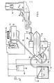
- a water injection system 10 adapted for use with an internal combustion engine 12.
- the engine 12 includes an air intake manifold 14.
- the engine 12 further includes a carburetor 16 schematically illustrated to the far right of Fig. 1.
- the water injection system 10 comprises a pump 18 shown in the central lower portion of Fig. 10.
- Pump 18 has an outlet 20 from which fluid flows when check valve 22 is open. Fluid passing through check valve 22 travels through piping .24 into spray nozzle 26. Spray nozzle 26 emits from its regulated output 28 a stream of water into the carburetor 16 of engine 12.
- Water enters the upper portion of pump 18 via piping 30.
- Piping 30 provides a fluid flow path between the pump 18 and water reservoir 32.
- the end of pipe 30 extending into the water reservoir 32 includes a filter 34.
- Water reservoir 32 is provided with an electrical float 36. When the water in reservoir 32 is low, the electric float 36 provides an electrical path through its contacts which allows light 38 to turn on.
- the lower portion of pump 18 has a relief air valve 40 and an auxiliary chamber 42 connected in air flow communication with manifold 14 via air hose 44.
- thermal relay 46 closes. Prior to relay 46 closing a check valve 22 is closed thereby preventing the injection of water into the carburetor 16. Once the thermal relay 46 closes, the electrical circuitry of the water injection system 10 becomes operable. In this regard energy through bistable switch 48 is provided.
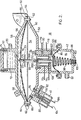
- the pump is shown to basically comprise four housings.
- the first housing is the main housing 50 having attached thereto an auxiliary housing 42 and a housing for air relief valve means 40.
- the last housing is pressure maintaining housing 52 shown attached to the top of housing 50.
- the main housing 50 provides a main chamber 54.
- the diaphragm 56 positioned within chamber 54 divides the chamber into two sub-compartments 58 and 60.
- Diaphragm 56 is held in place between flanges 62 and washer 64 by means of screws and bolts 66.
- Fluid in the sub-compartment 58 will comprise water while the fluid in sub-compartment 60 is air.
- Pressure maintaining housing 52 is provided with pump outlet 20. As illustrated, the pressure maintaining housing 52 is provided with a holding chamber 72.
- a portion of the holding chamber 72 comprises water while the upper portion of holding chamber 72 includes air 74.
- the lower sub-compartment 60 of the main chamber 54 is provided with an inlet 76.
- inlet 76 is either in air flow communication with air port 80 or air port 82.
- the air port 80 is connected to the atmosphere and allows air under atmospheric pressure to enter sub-compartment 60.
- port 82 is in air flow communication with inlet 76, the pressure within the sub-compartment 60 drops. This is because sub-compartment 6 0 will be in air flow communication with the manifold 14 and the negative back pressure developed in manifold 14.
- the auxiliary housing 42 of pump 18 includes an auxiliary chamber 84 subdivided by diaphragm 85 into auxiliary sub-compartments 86 and 88.
- Diaphragm 85 is secured to the auxiliary housing 42 in much the same manner as diaphragm 56 is secured to the main housing 50.
- Auxiliary sub-compartment 86 is in air flow communication with main sub-compartment 60 because of the air passageway 90 extending between these sub-compartments.
- the sub-compartment 88 is provided with a port 92 which is connected to air hose 44.
- sub-compartment 88 is in continuous air flow communication with the negative back pressure developed in the manifold 14 of engine 12.
- Pump 18 further includes a pressure inducing means generally illustrated at 94 that pressurizes the fluid contained with sub-compartment 58.
- the pressure inducing means 94 comprises diaphragm 56, actuating member or connecting rod 96, and spring means 98 attached to stud 100 and adjustable from the outside of the pump by adjustment means or nut 102. Nut 102 and stud 100 are adjusted such that spring 98 provides via connecting rod 96 and diaphragm 56 pressure on the fluid contained within sub-compartment 58. As illustrated, diaphragm 85 is interconnected with the rod 96 and spring 98.
- the air relief valve 40 is connected electrically with switch 48 via conductors 104 and 106.
- the auxiliary housing 42 includes a magnetizing means or solenoid coil shown generally at 108. Solenoid coil 108 when energized has an effect on connecting rod 96.
- Connecting rod 96 comprises a non-magnetic portion 96B and a magnetic portion 96A threaded together as shown at 110.
- the electrical connections of solenoid 108 are interconnected with switch means 48 via electrical lines 112 and 114. Lines 116 and l18 interconnect the D.C. voltage bus with the switch control means 48 on line 118.
- valve operates substantially as shown in Fig. 2. That is to say diaphragm 56 pressurizes the fluid in sub-compartment 58 due to the force of spring 98 minus any forces due to the effect of the negative back pressure in manifold 14. As the negative back pressure in manifold 14 varies, diaphragm 85 adjusts the position of diaphragm 56 via connecting rod 96, thereby varying the pressure of the fluid contained in sub-compartment 58. Pressurization of fluid in sub-compartment 58 results in the fluid moving into chamber 72 and out through outlet port 20 to the carburetor 16 of engine 14.
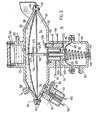
- variable pressure inducing means 94 moves into the position substantially as shown in Fig. 3.
- a lower push bar 120 causes contacts l22 to close.
- switching means 48 which in turn energizes the air valve 40 and vacuum assist solenoid 108.
- Energization of air relief valve 40 causes valve 78-to move into the position substantially as shown in Fig. 4. This results in the atmospheric pressure of air contained within sub-compartment 60 and sub-compartment 86 to drop to that of the negative back pressure in the manifold 14.
- the negative back pressure within sub-compartment 60 tends to draw diaphragm 56 downward thereby drawing additional fluid from the water reservoir 32 via piping 30 and in through inlet port 68 into sub-compartment 58.
- the solenoid 108 is energized and pulls the magnetic portion 96B of connecting rod 96 downwardly.
- the connecting rod 96 is pulled downwardly until such time as the actuating or pusher bar 124 brings contacts 126 into contact as shown in Fig. 4.
- pusher bar 124 is provided with a sleeve 123 that surrounds connecting rod 96.
- pusher bar 124 has an adjusting screw 125 that allows the location of pusher bar 124 on the rod 96 to be changed.
- the location of the pusher bar 124 can be changed to.vary the length of time of the water intake cycle. Fluid continues to leave the pump 18 via inlet 20 during the water intake cycle of the pump because of one-way valve 70 closing and because water in chamber 72 is under pressure due to the air pocket 74.
- the switch means 48 de-activates the valve 78 in relief air valve 40 so that the valve 78 moves back into the position shown substantially as in Fig. 2. This will bring the air pressure in the sub-compartment 60 and 86 back up to atmospheric pressure.
- switch means 48 de-activates solenoid 108. Diaphragm 56 is once again free to move into pressure inducing relation with the fluid contained in sub-compartment 58.
- the nozzle includes an auxiliary air flow path shown by arrows 130 and a primary air flow path shown by arrows 132.
- the nozzle includes a pressure sensitive means or piston 134 movable within cylinder 136.
- the auxiliary air flow path 130 is provided by cutting a notch out of the interior wall of cylinder 136.
- the auxiliary air flow channel 130 increases in size as it extends away from the inlet 138-of nozzle 26 towards the regulated orifice 128.
- a spring means in the form of coiled spring 140 is mounted to a spring lock 142 positioned in the groove 144 of the nozzle 26. The other end of spring 140 surrounds the nose 146 of piston 134.
- auxiliary fluid flow path 130 has an opening cross-section area that increases in size as the piston 134 moves towards the spring lock 142, the amount of fluid streaming out of nozzle 2.6 varies as the pressure of this fluid varies. It should be understood that because the piston 134 moves in response to a pressure build up within its conical walls, as the size of the inlet for auxiliary fluid path 130 increases, the buildup of fluid pressure within the cone of piston 134. Thus the position of the piston 134 stabilizes when the fluid pressure stabilizes.
- the magnetizing means or solenoid 108 is used to maintain the diaphragm 56 of the pressure inducing mean. 94 in pressure inducing relation with the water contained in main sub-compartment 58.
- the electrical conductors 116, 118 of solenoid 108 would be connected to an electronic control circuit.
- the electronic control circuit would vary the energization of solenoid 108 as a function of change in the RPM of the engine. This would cause the pressure inducing means to vary the pressure of the water contained in sub-compartment 58.
- the polarity of the connecting rod 96 would be changed. While this embodiment could be used during the normal.operation of the engine, it preferably would be used'for engines that have a lower negative back pressure developed in the intake manifold when operating at high RPM than at idling RPMs.
Priority Applications (1)
| Application Number | Priority Date | Filing Date | Title |
|---|---|---|---|
| AT83301729T ATE29766T1 (de) | 1982-04-13 | 1983-03-28 | Wasser-einspritzsystem fuer brennkraftmaschine. |
Applications Claiming Priority (2)
| Application Number | Priority Date | Filing Date | Title |
|---|---|---|---|
| US368030 | 1982-04-13 | ||
| US06/368,030 US4461245A (en) | 1982-04-13 | 1982-04-13 | Fluid injection system for internal combustion engine |
Publications (2)
| Publication Number | Publication Date |
|---|---|
| EP0091752A1 true EP0091752A1 (de) | 1983-10-19 |
| EP0091752B1 EP0091752B1 (de) | 1987-09-16 |
Family
ID=23449599
Family Applications (1)
| Application Number | Title | Priority Date | Filing Date |
|---|---|---|---|
| EP83301729A Expired EP0091752B1 (de) | 1982-04-13 | 1983-03-28 | Wasser-Einspritzsystem für Brennkraftmaschine |
Country Status (8)
| Country | Link |
|---|---|
| US (1) | US4461245A (de) |
| EP (1) | EP0091752B1 (de) |
| JP (1) | JPS58206868A (de) |
| AT (1) | ATE29766T1 (de) |
| AU (1) | AU563870B2 (de) |
| CA (1) | CA1192457A (de) |
| DE (1) | DE3373695D1 (de) |
| ZA (1) | ZA832276B (de) |
Cited By (2)
| Publication number | Priority date | Publication date | Assignee | Title |
|---|---|---|---|---|
| GB2313156A (en) * | 1996-05-16 | 1997-11-19 | Hsu Chih Cheng | Controlling supply of auxiliary water to the intake of an i.c. engine |
| US10364775B2 (en) | 2016-08-16 | 2019-07-30 | Ford Global Technologies, Llc | Water-injection anti-freezing system |
Families Citing this family (23)
| Publication number | Priority date | Publication date | Assignee | Title |
|---|---|---|---|---|
| US4960080A (en) * | 1989-02-28 | 1990-10-02 | Cummins Engine Company, Inc. | Pollution control apparatus and method for a turbodiesel motor-generator set |
| US5148776A (en) * | 1991-09-23 | 1992-09-22 | Connor Michael J | Coordinated water and fuel injection system |
| US5331924A (en) * | 1992-03-12 | 1994-07-26 | Kraus Gregory A | Catalytic liquid injection system for emission control |
| US5327875A (en) * | 1993-02-19 | 1994-07-12 | Hall S Franklin | Vapor enhanced carburetion system |
| CZ76397A3 (cs) * | 1994-09-12 | 1998-08-12 | Entherm, Inc. | Motor se vstřikováním vody do válce |
| US5694908A (en) * | 1996-05-08 | 1997-12-09 | Hsu; Chih-Cheng | Auxiliary water-supply sytem for an internal combustion engine |
| DE19819271A1 (de) * | 1998-04-30 | 1999-11-11 | Guenther Kramb | Dosiervorrichtung für eine Emulgieranlage |
| DE10194221D2 (de) * | 2000-09-30 | 2004-07-22 | Michael Hartkopf | Verfahren und Vorrichtung zur Reduzierung des Kraftstoffverbrauchs |
| FI115992B (fi) * | 2002-04-19 | 2005-08-31 | Marioff Corp Oy | Menetelmä ja laitteisto suihkutuslaitteiston ohjaamiseksi |
| FI112395B (fi) * | 2002-04-19 | 2003-11-28 | Marioff Corp Oy | Suihkutuspää |
| WO2005090772A1 (en) * | 2004-03-19 | 2005-09-29 | Sis Power, Inc. | Devices, systems and methods for introducing additives into an internal combustion engine |
| US20060249102A1 (en) * | 2004-11-04 | 2006-11-09 | S.I.S. Power, Inc | Devices, systems and methods for controlling introduction of additives into an internal combustion engine |
| US7216607B2 (en) * | 2005-05-27 | 2007-05-15 | Rival Technologies Inc. | Emission control water injection system for diesel engines |
| DE102009019791A1 (de) | 2009-05-02 | 2010-11-11 | Mazur, Ignatz | Nockenkolben-Verbrennungsmotor mit Brennstoff-Verbrennungswärme-Ausnutzung |
| DE102015208502A1 (de) | 2015-05-07 | 2016-11-10 | Robert Bosch Gmbh | Wassereinspritzvorrichtung einer Brennkraftmaschine |
| US9874163B1 (en) | 2016-08-02 | 2018-01-23 | Ford Global Technologies, Llc | Methods and system for adjusting engine operation based on evaporated and condensed portions of water injected at an engine |
| US10184429B2 (en) | 2016-08-02 | 2019-01-22 | Ford Global Technologies, Llc | Methods and system for selecting a location for water injection in an engine |
| US9976502B2 (en) | 2016-08-02 | 2018-05-22 | Ford Global Technologies, Llc | Methods and system for injecting water at different groups of cylinders of an engine |
| US10247140B2 (en) | 2016-12-19 | 2019-04-02 | Ford Global Technologies, Llc | Methods and system for adjusting engine water injection |
| US9945310B1 (en) | 2016-12-19 | 2018-04-17 | Ford Global Technologies, Llc | Methods and system for adjusting engine water injection |
| US10167819B2 (en) | 2016-12-19 | 2019-01-01 | Ford Global Technologies, Llc | Method and system for engine water injection |
| US10473061B2 (en) | 2017-03-21 | 2019-11-12 | Ford Global Technologies, Llc | Method and system for engine water injection |
| CN110238708B (zh) * | 2019-06-20 | 2024-01-23 | 中国工程物理研究院激光聚变研究中心 | 一种磁流变抛光机床磁流变液循环系统 |
Citations (10)
| Publication number | Priority date | Publication date | Assignee | Title |
|---|---|---|---|---|
| US2445337A (en) * | 1945-08-09 | 1948-07-20 | Hugh S Robinson | Injection control system |
| DE835818C (de) * | 1941-02-04 | 1952-04-03 | Daimler Benz Ag | Einspritzventil fuer Brennkraftmaschinen |
| US2611345A (en) * | 1947-04-11 | 1952-09-23 | Sudmeier Gus | Water or vapor injector for internal-combustion engines |
| US2756729A (en) * | 1955-01-17 | 1956-07-31 | Victor Lundy | Apparatus for supplying water to the fuel and air mixture for internal-combustion engine |
| DE1138637B (de) * | 1959-07-21 | 1962-10-25 | Grundstuecksverwaltungsgesells | Doppelmembranpumpe, insbesondere Kraftstoffpumpe |
| US3227314A (en) * | 1964-03-03 | 1966-01-04 | Porter Lancastrian Ltd | Delivering of measured quantities of pressurised liquids |
| US3816034A (en) * | 1971-03-12 | 1974-06-11 | Dorr Oliver Inc | Diaphragm pumps and actuating system therefor |
| US3845745A (en) * | 1972-07-03 | 1974-11-05 | C Dunlap | Water injection system for an internal combustion engine |
| GB2007763A (en) * | 1977-11-15 | 1979-05-23 | Maschf Augsburg Nuernberg Ag | Fuel injector for an internal combustion engine |
| GB2041075A (en) * | 1979-01-05 | 1980-09-03 | Alonzo L D | Fluid metering pump actuated by a pressurized fluid |
Family Cites Families (17)
| Publication number | Priority date | Publication date | Assignee | Title |
|---|---|---|---|---|
| DE179265C (de) * | ||||
| DE553673C (de) * | 1931-10-11 | 1932-06-29 | Siemens Schuckertwerke Akt Ges | Elektromagnetische Membranpumpe |
| US1981891A (en) * | 1932-05-20 | 1934-11-27 | Woermann Jacob | Vaporizer for gas engines |
| US2570394A (en) * | 1949-02-23 | 1951-10-09 | Edwin S Shultz | Steam induction device for manifolds |
| US2606537A (en) * | 1950-07-08 | 1952-08-12 | William M Baumheckel | Apparatus for supplemental selective feeding of water and alcohol in an engine fuel feed device |
| US2687120A (en) * | 1950-08-26 | 1954-08-24 | Jerry P Malec | Mositure injection system |
| US3196606A (en) * | 1961-10-30 | 1965-07-27 | Garrett Corp | Antidetonant control for turbocharged engines |
| US3631843A (en) * | 1969-12-09 | 1972-01-04 | John O Yeiser | Fluid addition system for internal combustion engines |
| JPS51110123A (en) * | 1971-03-29 | 1976-09-29 | Tooru Ando | gasorinkikan no judokugasuboshihoho |
| US3865907A (en) * | 1973-01-17 | 1975-02-11 | Howard P Rock | Needle valve vapor injection and method |
| US3911871A (en) * | 1974-01-23 | 1975-10-14 | Rockwell International Corp | Fluid injection system for internal combustion engines |
| US4059078A (en) * | 1974-09-09 | 1977-11-22 | Ramiro De La Rosa Raul | Steam injection apparatus |
| JPS5844857B2 (ja) * | 1975-11-07 | 1983-10-05 | トヨタ自動車株式会社 | ミズテンカキコウオユウスル ナイネンキカン |
| US3987774A (en) * | 1975-11-26 | 1976-10-26 | Waag Norman E | Supplementary fuel injection apparatus for the internal combustion engine |
| US4188928A (en) * | 1977-02-23 | 1980-02-19 | Faustinos Carlos Q | Fuel vaporizing apparatus for internal combustion engines |
| US4240380A (en) * | 1977-03-21 | 1980-12-23 | Slagle Bernie L | Water injection system |
| DE2807514C3 (de) * | 1978-02-22 | 1980-08-14 | Pierburg Gmbh & Co Kg, 4040 Neuss | Membranpumpe |
-
1982
- 1982-04-13 US US06/368,030 patent/US4461245A/en not_active Expired - Fee Related
-
1983
- 1983-03-23 AU AU12760/83A patent/AU563870B2/en not_active Ceased
- 1983-03-28 EP EP83301729A patent/EP0091752B1/de not_active Expired
- 1983-03-28 CA CA000424630A patent/CA1192457A/en not_active Expired
- 1983-03-28 AT AT83301729T patent/ATE29766T1/de not_active IP Right Cessation
- 1983-03-28 DE DE8383301729T patent/DE3373695D1/de not_active Expired
- 1983-03-30 ZA ZA832276A patent/ZA832276B/xx unknown
- 1983-04-12 JP JP58063106A patent/JPS58206868A/ja active Granted
Patent Citations (10)
| Publication number | Priority date | Publication date | Assignee | Title |
|---|---|---|---|---|
| DE835818C (de) * | 1941-02-04 | 1952-04-03 | Daimler Benz Ag | Einspritzventil fuer Brennkraftmaschinen |
| US2445337A (en) * | 1945-08-09 | 1948-07-20 | Hugh S Robinson | Injection control system |
| US2611345A (en) * | 1947-04-11 | 1952-09-23 | Sudmeier Gus | Water or vapor injector for internal-combustion engines |
| US2756729A (en) * | 1955-01-17 | 1956-07-31 | Victor Lundy | Apparatus for supplying water to the fuel and air mixture for internal-combustion engine |
| DE1138637B (de) * | 1959-07-21 | 1962-10-25 | Grundstuecksverwaltungsgesells | Doppelmembranpumpe, insbesondere Kraftstoffpumpe |
| US3227314A (en) * | 1964-03-03 | 1966-01-04 | Porter Lancastrian Ltd | Delivering of measured quantities of pressurised liquids |
| US3816034A (en) * | 1971-03-12 | 1974-06-11 | Dorr Oliver Inc | Diaphragm pumps and actuating system therefor |
| US3845745A (en) * | 1972-07-03 | 1974-11-05 | C Dunlap | Water injection system for an internal combustion engine |
| GB2007763A (en) * | 1977-11-15 | 1979-05-23 | Maschf Augsburg Nuernberg Ag | Fuel injector for an internal combustion engine |
| GB2041075A (en) * | 1979-01-05 | 1980-09-03 | Alonzo L D | Fluid metering pump actuated by a pressurized fluid |
Cited By (2)
| Publication number | Priority date | Publication date | Assignee | Title |
|---|---|---|---|---|
| GB2313156A (en) * | 1996-05-16 | 1997-11-19 | Hsu Chih Cheng | Controlling supply of auxiliary water to the intake of an i.c. engine |
| US10364775B2 (en) | 2016-08-16 | 2019-07-30 | Ford Global Technologies, Llc | Water-injection anti-freezing system |
Also Published As
| Publication number | Publication date |
|---|---|
| JPS58206868A (ja) | 1983-12-02 |
| AU1276083A (en) | 1983-10-20 |
| ZA832276B (en) | 1983-12-28 |
| JPH0359268B2 (de) | 1991-09-10 |
| CA1192457A (en) | 1985-08-27 |
| DE3373695D1 (en) | 1987-10-22 |
| US4461245A (en) | 1984-07-24 |
| EP0091752B1 (de) | 1987-09-16 |
| ATE29766T1 (de) | 1987-10-15 |
| AU563870B2 (en) | 1987-07-23 |
Similar Documents
| Publication | Publication Date | Title |
|---|---|---|
| US4461245A (en) | Fluid injection system for internal combustion engine | |
| EP0191791B1 (de) | Verfahren und vorrichtung zum dosieren von brennstoffen | |
| US4807583A (en) | Fuel pumping apparatus | |
| US4300515A (en) | Apparatus for actuating an adjustment device acting upon a control apparatus for exhaust recirculation in internal combustion engines | |
| EP0363448B1 (de) | Flüssigkeitsservosystem für brennstoffeinspritzung und sonstige anwendungen | |
| EP0072034B1 (de) | Kraftstoffeinspritzanlage für Verbrennungsmotoren und ein Motor versehen mit einer solchen Anlage | |
| SU1074419A3 (ru) | Регул тор давлени газообразного топлива дл двигател внутреннего сгорани | |
| US4404945A (en) | Fuel-supply control system for gas-turbine engine | |
| US4110417A (en) | Variable venturi type carburetor | |
| US4071585A (en) | Variable venturi type carburetor | |
| US3931802A (en) | Fuel injection system for internal combustion engines | |
| EP0297546B1 (de) | Kraftstoffdruckregler für Brennkraftmaschinen | |
| US2880790A (en) | Starting fuel control for gas turbine engines | |
| JPH0160661B2 (de) | ||
| US4433662A (en) | Fuel supply system | |
| US3916856A (en) | Fuel injection systems for internal combustion engines | |
| SE466864B (sv) | Foerfarande och anordning foer braensleinsprutning med hjaelp av tryckluft vid foerbraenningsmotor | |
| SU1435394A1 (ru) | Устройство дл дозировани жидкого металла | |
| JPH0333472A (ja) | 圧力調整器 | |
| RU2120052C1 (ru) | Система центрального впрыска газа для двигателя внутреннего сгорания | |
| EP0049800B1 (de) | Brennstoffeinspritz- und -regelsystem | |
| SU1072010A1 (ru) | Регул тор давлени | |
| RU2028496C1 (ru) | Система питания дизеля топливом | |
| SU1352466A2 (ru) | Регул тор давлени | |
| IE41975B1 (en) | Air supply system for the inlet manifold of an internal co mbustion engine |
Legal Events
| Date | Code | Title | Description |
|---|---|---|---|
| PUAI | Public reference made under article 153(3) epc to a published international application that has entered the european phase |
Free format text: ORIGINAL CODE: 0009012 |
|
| AK | Designated contracting states |
Designated state(s): AT BE CH DE FR GB IT LI LU NL SE |
|
| 17P | Request for examination filed |
Effective date: 19840412 |
|
| GRAA | (expected) grant |
Free format text: ORIGINAL CODE: 0009210 |
|
| AK | Designated contracting states |
Kind code of ref document: B1 Designated state(s): AT BE CH DE FR GB IT LI LU NL SE |
|
| PG25 | Lapsed in a contracting state [announced via postgrant information from national office to epo] |
Ref country code: NL Effective date: 19870916 Ref country code: LI Effective date: 19870916 Ref country code: CH Effective date: 19870916 Ref country code: BE Effective date: 19870916 Ref country code: AT Effective date: 19870916 |
|
| REF | Corresponds to: |
Ref document number: 29766 Country of ref document: AT Date of ref document: 19871015 Kind code of ref document: T |
|
| PG25 | Lapsed in a contracting state [announced via postgrant information from national office to epo] |
Ref country code: SE Effective date: 19870930 |
|
| REF | Corresponds to: |
Ref document number: 3373695 Country of ref document: DE Date of ref document: 19871022 |
|
| ITF | It: translation for a ep patent filed |
Owner name: UFFICIO BREVETTI RICCARDI & C. |
|
| REG | Reference to a national code |
Ref country code: CH Ref legal event code: PL |
|
| ET | Fr: translation filed | ||
| NLV1 | Nl: lapsed or annulled due to failure to fulfill the requirements of art. 29p and 29m of the patents act | ||
| PG25 | Lapsed in a contracting state [announced via postgrant information from national office to epo] |
Ref country code: LU Free format text: LAPSE BECAUSE OF NON-PAYMENT OF DUE FEES Effective date: 19880331 |
|
| PLBE | No opposition filed within time limit |
Free format text: ORIGINAL CODE: 0009261 |
|
| STAA | Information on the status of an ep patent application or granted ep patent |
Free format text: STATUS: NO OPPOSITION FILED WITHIN TIME LIMIT |
|
| 26N | No opposition filed | ||
| ITTA | It: last paid annual fee | ||
| PGFP | Annual fee paid to national office [announced via postgrant information from national office to epo] |
Ref country code: GB Payment date: 19920327 Year of fee payment: 10 |
|
| PGFP | Annual fee paid to national office [announced via postgrant information from national office to epo] |
Ref country code: FR Payment date: 19920331 Year of fee payment: 10 |
|
| PGFP | Annual fee paid to national office [announced via postgrant information from national office to epo] |
Ref country code: DE Payment date: 19920526 Year of fee payment: 10 |
|
| PG25 | Lapsed in a contracting state [announced via postgrant information from national office to epo] |
Ref country code: GB Effective date: 19930328 |
|
| GBPC | Gb: european patent ceased through non-payment of renewal fee |
Effective date: 19930328 |
|
| PG25 | Lapsed in a contracting state [announced via postgrant information from national office to epo] |
Ref country code: FR Effective date: 19931130 |
|
| PG25 | Lapsed in a contracting state [announced via postgrant information from national office to epo] |
Ref country code: DE Effective date: 19931201 |
|
| REG | Reference to a national code |
Ref country code: FR Ref legal event code: ST |