EP0091085B2 - Dieselbrennkraftmaschine - Google Patents
Dieselbrennkraftmaschine Download PDFInfo
- Publication number
- EP0091085B2 EP0091085B2 EP83103145A EP83103145A EP0091085B2 EP 0091085 B2 EP0091085 B2 EP 0091085B2 EP 83103145 A EP83103145 A EP 83103145A EP 83103145 A EP83103145 A EP 83103145A EP 0091085 B2 EP0091085 B2 EP 0091085B2
- Authority
- EP
- European Patent Office
- Prior art keywords
- channel
- approximately
- swirl chamber
- piston
- angle
- Prior art date
- Legal status (The legal status is an assumption and is not a legal conclusion. Google has not performed a legal analysis and makes no representation as to the accuracy of the status listed.)
- Expired - Lifetime
Links
- 238000002485 combustion reaction Methods 0.000 claims description 7
- 230000001154 acute effect Effects 0.000 claims description 3
- UGFAIRIUMAVXCW-UHFFFAOYSA-N Carbon monoxide Chemical compound [O+]#[C-] UGFAIRIUMAVXCW-UHFFFAOYSA-N 0.000 description 3
- 239000003546 flue gas Substances 0.000 description 3
- 238000005520 cutting process Methods 0.000 description 2
- 239000000779 smoke Substances 0.000 description 2
- 238000005242 forging Methods 0.000 description 1
- 239000000446 fuel Substances 0.000 description 1
- 239000007789 gas Substances 0.000 description 1
- 229930195733 hydrocarbon Natural products 0.000 description 1
- 150000002430 hydrocarbons Chemical class 0.000 description 1
- 238000002347 injection Methods 0.000 description 1
- 239000007924 injection Substances 0.000 description 1
- 238000004519 manufacturing process Methods 0.000 description 1
- 238000000034 method Methods 0.000 description 1
- 239000004071 soot Substances 0.000 description 1
Images
Classifications
-
- F—MECHANICAL ENGINEERING; LIGHTING; HEATING; WEAPONS; BLASTING
- F02—COMBUSTION ENGINES; HOT-GAS OR COMBUSTION-PRODUCT ENGINE PLANTS
- F02B—INTERNAL-COMBUSTION PISTON ENGINES; COMBUSTION ENGINES IN GENERAL
- F02B19/00—Engines characterised by precombustion chambers
- F02B19/14—Engines characterised by precombustion chambers with compression ignition
-
- F—MECHANICAL ENGINEERING; LIGHTING; HEATING; WEAPONS; BLASTING
- F02—COMBUSTION ENGINES; HOT-GAS OR COMBUSTION-PRODUCT ENGINE PLANTS
- F02B—INTERNAL-COMBUSTION PISTON ENGINES; COMBUSTION ENGINES IN GENERAL
- F02B19/00—Engines characterised by precombustion chambers
- F02B19/16—Chamber shapes or constructions not specific to sub-groups F02B19/02 - F02B19/10
- F02B19/18—Transfer passages between chamber and cylinder
-
- F—MECHANICAL ENGINEERING; LIGHTING; HEATING; WEAPONS; BLASTING
- F02—COMBUSTION ENGINES; HOT-GAS OR COMBUSTION-PRODUCT ENGINE PLANTS
- F02B—INTERNAL-COMBUSTION PISTON ENGINES; COMBUSTION ENGINES IN GENERAL
- F02B3/00—Engines characterised by air compression and subsequent fuel addition
- F02B3/06—Engines characterised by air compression and subsequent fuel addition with compression ignition
-
- Y—GENERAL TAGGING OF NEW TECHNOLOGICAL DEVELOPMENTS; GENERAL TAGGING OF CROSS-SECTIONAL TECHNOLOGIES SPANNING OVER SEVERAL SECTIONS OF THE IPC; TECHNICAL SUBJECTS COVERED BY FORMER USPC CROSS-REFERENCE ART COLLECTIONS [XRACs] AND DIGESTS
- Y02—TECHNOLOGIES OR APPLICATIONS FOR MITIGATION OR ADAPTATION AGAINST CLIMATE CHANGE
- Y02T—CLIMATE CHANGE MITIGATION TECHNOLOGIES RELATED TO TRANSPORTATION
- Y02T10/00—Road transport of goods or passengers
- Y02T10/10—Internal combustion engine [ICE] based vehicles
- Y02T10/12—Improving ICE efficiencies
Definitions
- the invention relates to a diesel internal combustion engine with a swirl chamber accommodated off-center in the cylinder head and an overflow channel arranged off-center to the piston in the swirl chamber bottom, which is directed at an acute angle (channel angle) to the parting plane between the cylinder head and the cylinder block and has a lenticular cross section like that of a plano-convex lens with a rounded Has corners.
- the lower, outer wall of the overflow channel is curved convexly, while the upper wall, which is directed towards the center of the piston, is flat or planar.
- the free duct cross section is approximately 0.48 cm 2 , which corresponds to approximately 1/100 of the piston area.
- US-A-4 300 381 discloses various embodiments of the swirl chamber base and relates to the production method for a swirl chamber insert forming the swirl chamber base, in which, in the drop forging process, a blank is first forged in a first die and the contours of the insert are completed in a second die towards completion through further cutting or non-cutting processing steps with the help of special tools for introducing the overflow channel.
- a channel angle of 15 ° to 75 ° to the longitudinal central axis of the insert is specified, while various configurations from oval to circular with a flattened side or two parallel flat sides are disclosed for the channel cross section.
- the invention is intended to reduce black smoke emissions and to reduce noise.
- this object is achieved with a diesel internal combustion engine of the type described at the outset in that the upper inner overflow channel wall directed towards the center of the piston is convex and the lower, outer channel wall is flat (plan) and in that the overflow channel has a cross-sectional area of approximately 1% to 0.70%. the piston surface and a channel angle (a) of about 37 ° to 44 °.
- the cross-section of the swirl chamber of the swirl chamber is advantageously approximately 0.39 cm 2 and the channel angle (a) is approximately 40 °.
- the invention significantly reduces the flue gas emission and the engine noise. Depending on the speed, the flue gas emissions alone are reduced by between 75% and 90%. The more economical combustion also results in fuel savings of around 10%. Overall, there is a "softer" combustion (more pleasant noise) with less unburned hydrocarbons and less soot in the exhaust gas.
- the swirl chamber 2 denotes the swirl chamber, 3 the injection nozzle and 4 the glow plug.
- Part of the swirl chamber 2 is the swirl chamber insert 2 'with the overflow channel 7 opening at an acute angle to the main combustion chamber 5 of the piston 6.
- the inflow angle a which the overflow channel 7 forms with the parting plane 8 between the cylinder head 1 and the cylinder block 9, is 40 ° .
- the overflow channel 7 has the cross-sectional shape of a plano-convex converging lens with rounded corners 10.
- the convex surface 11 forms the upper inner wall directed towards the center of the piston and the flat surface designated 12 the lower, outer wall of the overflow channel 7.
Landscapes
- Engineering & Computer Science (AREA)
- Chemical & Material Sciences (AREA)
- Combustion & Propulsion (AREA)
- Mechanical Engineering (AREA)
- General Engineering & Computer Science (AREA)
- Combustion Methods Of Internal-Combustion Engines (AREA)
- Cylinder Crankcases Of Internal Combustion Engines (AREA)
Description
- Die Erfindung betrifft eine Dieselbrennkraftmaschine mit einer außermittig im Zylinderkopf untergebrachten Wirbelkammer und einem im Wirbelkammerboden außermittig zum Kolben angeordneten Überströmkanal, der unter einem spitzen Winkel (Kanalwinkel) zur Trennebene zwischen Zylinderkopf und Zylinderblock gerichtet ist und einen linsenförmigen Querschnitt wie bei einer Plankonvex-Linse mit abgerundeten Ecken aufweist.
- Bei einer aus der DE-A-2 703 228 bekannten Wirbelkammerausbildung dieser Art ist die untere, äußere Wandung des Überströmkanals konvex gewölbt, während die obere, zur Kolbenmitte hin gerichtete Wandung plan bzw. eben verläuft. Bei einem Kanalwinkel von 35° zur Trennebene zwischen Zylinderkopf und Zylinderblock beträgt der freie Kanalquerschnitt etwa 0,48 cm2, was etwa 1/100 der Kolbenfläche entspricht. Mit diesen Konfigurationen sind die durch die bestehenden internationalen Bestimmungen über die Schwarzrauchemission (ECE R 24.02) oder das Motorgeräusch (EG 70/157) vorgegebenen Grenzen der Zulässigkeitswerte erreicht.
- Die US-A-4 300 381 offenbart verschiedene Ausführungsformen des Wirbelkammerbodens und bezieht sich auf das Herstellungsverfahren für einen den Wirbelkammerboden bildenden Wirbelkammereinsatz, bei dem im Gesenkschmiedeverfahren zunächst in einem ersten Gesenk ein Rohling geschmiedet und in einem zweiten Gesenk die Konturen des Einsatzes vervollständigt werden bis hin zur Fertigstellung durch weitere spanende oder spanlose Bearbeitungsgänge mit Hilfe von Sonderwerkzeugen zum Einbringen des Überströmkanals. Ohne funktionelle Bezugnahme ist hierbei ein Kanalwinkel von 15° bis 75° zur Längsmittelachse des Einsatzes angegeben, während für den Kanalquerschnitt verschiedene Konfigurationen von oval bis kreisförmig mit jeweils einer abgeflachten Seite oder zwei parallel zueinander gerichteten flachen Seiten offenbart sind.
- Durch die Erfindung sollen die Schwarzrauchemission verringert und eine Geräuschabsenkung erreicht werden.
- Erfindungsgemäß wird diese Aufgabe mit einer Dieselbrennkraftmaschine der eingangs geschilderten Gattung dadurch gelöst, daß die obere zur Kolbenmitte gerichtete innere Überströmkanalwand konvex und die untere, äußere Kanalwand eben (plan) ausgebildet ist und daß der Überströmkanal eine Querschnittsfläche von etwa 1 % bis 0,70 % der Kolbenfläche und einen Kanalwinkel (a) von etwa 37° bis 44° aufweist. Vorteilhaft beträgt hierbei der Überströmkanalquerschnitt der Wirbelkammer etwa 0,39 cm2 und der Kanalwinkel (a) etwa 40°.
- Durch die Erfindung werden die Rauchgasemission und das Motorgeräusch erheblich vermindert. Allein die Rauchgasemission wird je nach Drehzahl etwa zwischen 75 % und 90 % gesenkt. Durch die günstigere Verbrennung wird auch eine Kraftstoffeinsparung von etwa 10 % erzielt. Insgesamt ergibt sich eine "weichere" Verbrennung (angenehmeres Geräusch) mit weniger unverbrannten Kohlenwasserstoffen und weniger Rußanteil im Abgas.
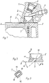
- Die Erfindung ist anhand eines Ausführungsbeispieles in den Zeichnungen dargestellt und anschließend näher erläutert. Es zeigen:
- Fig. 1 einen Teilausschnitt des Zylinderblockes im oberen Zylinderbereich und des Zylinderkopfes im Bereich der Wirbelkammer im Längsschnitt,
- Fig. 2 den Wirbelkammereinsatz im Längsschnitt und
- Fig. 3 einen Schnitt durch den Überströmkanal des Wirbelkammereinsatzes nach Linie 111 - 111 in Fig. 2.
- In dem Zylinderkopf 1 sind mit 2 die Wirbelkammer, mit 3 die Einspritzdüse und mit 4 die Glühkerze bezeichnet. Einen Teil der Wirbelkammer 2 bildet der Wirbelkammereinsatz 2' mit dem unter einem spitzen Winkel zu dem Hauptbrennraum 5 des Kolben 6 mündenden Überströmkanal 7. Der Einströmwinkel a, den der Überströmkanal 7 mit der Trennebene 8 zwischen Zylinderkopf 1 und Zylinderblock 9 bildet, beträgt 40°. Der Überströmkanal 7 hat die Querschnittsform einer plankonvexen Sammellinse mit abgerundeten Ecken 10. Hierbei bildet die konvex ausgebildete Fläche 11 die obere, zur Kolbenmitte hin gerichtete Innenwand und die mit 12 bezeichnete ebene Fläche die untere, äußere Wand des Überströmkanals 7. Bei einem Länge- zu Breite-Verhältnis dieses Kanalquerschnitts von etwa 2 : 1 ergibt sich eine Querschnittsfläche vom etwa 0,39 cm2. Die gemessene Rauchgasemission bei einer Drehzahl von 3 000 UPM lag bei 0,8 und bei der Nenndrehzahl von 4 600 UPM bei 0,4 nach der ECE Richtlinie und damit wesentlich unter den dort angegebenen Grenzwerten.
Claims (2)
Applications Claiming Priority (2)
| Application Number | Priority Date | Filing Date | Title |
|---|---|---|---|
| DE19828209819U DE8209819U1 (de) | 1982-04-06 | 1982-04-06 | Dieselbrennkraftmaschine |
| DE8209819U | 1982-04-06 |
Publications (3)
| Publication Number | Publication Date |
|---|---|
| EP0091085A1 EP0091085A1 (de) | 1983-10-12 |
| EP0091085B1 EP0091085B1 (de) | 1986-09-10 |
| EP0091085B2 true EP0091085B2 (de) | 1990-02-28 |
Family
ID=6738805
Family Applications (1)
| Application Number | Title | Priority Date | Filing Date |
|---|---|---|---|
| EP83103145A Expired - Lifetime EP0091085B2 (de) | 1982-04-06 | 1983-03-30 | Dieselbrennkraftmaschine |
Country Status (5)
| Country | Link |
|---|---|
| US (1) | US4434758A (de) |
| EP (1) | EP0091085B2 (de) |
| CA (1) | CA1220106A (de) |
| DE (2) | DE8209819U1 (de) |
| ES (1) | ES279841Y (de) |
Families Citing this family (6)
| Publication number | Priority date | Publication date | Assignee | Title |
|---|---|---|---|---|
| JPS60153420A (ja) * | 1984-01-21 | 1985-08-12 | Mitsubishi Heavy Ind Ltd | 副室式機関の燃焼室 |
| JP2689132B2 (ja) * | 1988-06-02 | 1997-12-10 | ヤマハ発動機株式会社 | 2サイクルディーゼルエンジン |
| JP3406119B2 (ja) * | 1995-06-05 | 2003-05-12 | ヤマハ発動機株式会社 | うず室式副燃焼室付き2サイクルディーゼルエンジン |
| US6363898B1 (en) | 1996-11-14 | 2002-04-02 | Quik-Change International, Llc | Quick replacement igniter assembly |
| US6152095A (en) * | 1996-11-14 | 2000-11-28 | Quik-Change Int'l., L.L.C. | Quick replacement spark plug assembly |
| JP2003343324A (ja) * | 2002-05-29 | 2003-12-03 | Toyota Motor Corp | ディーゼルエンジン制御方法及び装置 |
Family Cites Families (13)
| Publication number | Priority date | Publication date | Assignee | Title |
|---|---|---|---|---|
| GB226862A (en) | 1923-09-22 | 1924-12-22 | Samuel John Fielding | Improvements in the combustion chambers of internal combustion engines |
| US2003311A (en) | 1931-01-13 | 1935-06-04 | Ricardo Harry Ralph | Internal combustion engine of the liquid fuel injection compression ignition type |
| GB431345A (en) | 1934-01-04 | 1935-07-04 | Ricardo Harry Ralph | Improvements in or relating to the combustion chambers of internal combustion engines of the compression ignition type |
| GB439426A (en) | 1934-06-06 | 1935-12-06 | Harry Ralph Ricardo | Improvements in or relating to internal combustion engines of the liquid-fuel injection compression-ignition type |
| US2316794A (en) | 1941-07-24 | 1943-04-20 | George T Johnson | Combustion chamber |
| US2821177A (en) | 1954-10-11 | 1958-01-28 | Ricardo & Co Engineers | Internal combustion engines of the compression ignition type |
| US2795215A (en) | 1955-08-22 | 1957-06-11 | Ricardo & Co Engineers | Internal combustion engines of the compression ignition liquid fuel injection type |
| US2911959A (en) | 1956-07-05 | 1959-11-10 | Ricardo & Co Eugineers 1927 Lt | Internal combustion engines of the compression ignition type |
| FR1344892A (fr) * | 1962-05-28 | 1963-12-06 | Applic Tech Ind Lati | Perfectionnements aux moteurs à combustion interne à injection de carburant |
| GB1469106A (en) * | 1973-06-05 | 1977-03-30 | Ricardo & Co Engineers | Ic engines |
| US4122805A (en) | 1976-08-02 | 1978-10-31 | General Motors Corporation | Diesel engine combustion chambers |
| DE2703228C2 (de) * | 1977-01-27 | 1984-08-23 | Volkswagenwerk Ag, 3180 Wolfsburg | Luftverdichtende, selbstzündende Einspritz-Brennkraftmaschine |
| US4300381A (en) * | 1980-08-15 | 1981-11-17 | Riken Corporation | Method for producing insert for diesel engine combustion chamber |
-
1982
- 1982-04-06 DE DE19828209819U patent/DE8209819U1/de not_active Expired
-
1983
- 1983-03-23 ES ES1983279841U patent/ES279841Y/es not_active Expired
- 1983-03-30 DE DE8383103145T patent/DE3365974D1/de not_active Expired
- 1983-03-30 EP EP83103145A patent/EP0091085B2/de not_active Expired - Lifetime
- 1983-03-31 US US06/480,714 patent/US4434758A/en not_active Expired - Lifetime
- 1983-04-05 CA CA000425248A patent/CA1220106A/en not_active Expired
Also Published As
| Publication number | Publication date |
|---|---|
| EP0091085A1 (de) | 1983-10-12 |
| ES279841U (es) | 1984-11-16 |
| CA1220106A (en) | 1987-04-07 |
| DE8209819U1 (de) | 1982-08-05 |
| US4434758A (en) | 1984-03-06 |
| DE3365974D1 (en) | 1986-10-16 |
| ES279841Y (es) | 1985-06-01 |
| EP0091085B1 (de) | 1986-09-10 |
Similar Documents
| Publication | Publication Date | Title |
|---|---|---|
| DE69007899T2 (de) | Brennraum für Diesel-Brennkraftmaschine. | |
| EP0598941B1 (de) | Fremdgezündete Brennkraftmaschine mit einem im Kolben zugeordneten Brennraum | |
| DE60016099T2 (de) | Direkteinspritzbrennkraftmaschine mit Fremdzündung | |
| DE2739419A1 (de) | Brennraum fuer brennkraftmaschinen mit direkter einspritzung | |
| DE2652662C2 (de) | Brennkraftmaschine | |
| DE3718083C2 (de) | ||
| DE2909419A1 (de) | Brennkammer fuer brennkraftmaschinen mit direkter einspritzung | |
| EP0091085B2 (de) | Dieselbrennkraftmaschine | |
| EP0025831A1 (de) | Tauchkolben Ottomotor mit Kolben mit Erhebungen am Kolbenboden | |
| EP0225980B1 (de) | Gemischverdichtende Brennkraftmaschine, insbesondere fremdgezündete Viertaktbrennkraftmaschine | |
| DE19716642A1 (de) | Mehrzylinder-Ottomotor mit Kraftstoffdirekteinspritzung | |
| DE2950754C2 (de) | Gemischansaugende Brennkraftmaschine | |
| DE3742574C1 (en) | Internal-combustion engine with a combustion space in the piston head | |
| DE3901225C2 (de) | Mehrventil-Brennkraftmaschine | |
| EP1034366A1 (de) | Kolben für eine kolbenbrennkraftmaschine | |
| DE2359058A1 (de) | Verbrennungsraum fuer die zylinderkoepfe von viertaktbrennkraftmaschinen | |
| DE102018133550B4 (de) | Verbrennungskraftmaschine | |
| DE2751993C2 (de) | Gemischansaugende Brennkraftmaschine mit Quetschspalten | |
| EP0953758A1 (de) | Zylinderkopf | |
| DE3137738C1 (de) | Brennkraftmaschine mit Fremdzuendung | |
| DE2501518A1 (de) | Gemischverdichtende brennkraftmaschine mit fremdzuendung | |
| AT528499B1 (de) | Brennkraftmaschine | |
| DE19705659A1 (de) | Verfahren zum Betreiben einer Brennkraftmaschine | |
| DE102005035296B4 (de) | Verfahren zur Herstellung von Hubkolbenmaschinen sowie Hubkolbenmaschine | |
| DE2908293C2 (de) | Einlaßkanal für Brennkraftmaschinen |
Legal Events
| Date | Code | Title | Description |
|---|---|---|---|
| PUAI | Public reference made under article 153(3) epc to a published international application that has entered the european phase |
Free format text: ORIGINAL CODE: 0009012 |
|
| AK | Designated contracting states |
Designated state(s): DE FR GB IT SE |
|
| 17P | Request for examination filed |
Effective date: 19840224 |
|
| ITF | It: translation for a ep patent filed | ||
| GRAA | (expected) grant |
Free format text: ORIGINAL CODE: 0009210 |
|
| AK | Designated contracting states |
Kind code of ref document: B1 Designated state(s): DE FR GB IT SE |
|
| REF | Corresponds to: |
Ref document number: 3365974 Country of ref document: DE Date of ref document: 19861016 |
|
| ET | Fr: translation filed | ||
| PLBI | Opposition filed |
Free format text: ORIGINAL CODE: 0009260 |
|
| 26 | Opposition filed |
Opponent name: KLOECKNER-HUMBOLDT-DEUTZ AG Effective date: 19870603 |
|
| ITF | It: translation for a ep patent filed | ||
| PUAH | Patent maintained in amended form |
Free format text: ORIGINAL CODE: 0009272 |
|
| STAA | Information on the status of an ep patent application or granted ep patent |
Free format text: STATUS: PATENT MAINTAINED AS AMENDED |
|
| 27A | Patent maintained in amended form |
Effective date: 19900228 |
|
| AK | Designated contracting states |
Kind code of ref document: B2 Designated state(s): DE FR GB IT SE |
|
| ET3 | Fr: translation filed ** decision concerning opposition | ||
| ITTA | It: last paid annual fee | ||
| EAL | Se: european patent in force in sweden |
Ref document number: 83103145.5 |
|
| PGFP | Annual fee paid to national office [announced via postgrant information from national office to epo] |
Ref country code: SE Payment date: 19950228 Year of fee payment: 13 Ref country code: GB Payment date: 19950228 Year of fee payment: 13 |
|
| PGFP | Annual fee paid to national office [announced via postgrant information from national office to epo] |
Ref country code: FR Payment date: 19950322 Year of fee payment: 13 |
|
| PGFP | Annual fee paid to national office [announced via postgrant information from national office to epo] |
Ref country code: DE Payment date: 19950512 Year of fee payment: 13 |
|
| PG25 | Lapsed in a contracting state [announced via postgrant information from national office to epo] |
Ref country code: GB Effective date: 19960330 |
|
| PG25 | Lapsed in a contracting state [announced via postgrant information from national office to epo] |
Ref country code: SE Effective date: 19960331 |
|
| GBPC | Gb: european patent ceased through non-payment of renewal fee |
Effective date: 19960330 |
|
| PG25 | Lapsed in a contracting state [announced via postgrant information from national office to epo] |
Ref country code: FR Effective date: 19961129 |
|
| PG25 | Lapsed in a contracting state [announced via postgrant information from national office to epo] |
Ref country code: DE Effective date: 19961203 |
|
| EUG | Se: european patent has lapsed |
Ref document number: 83103145.5 |
|
| REG | Reference to a national code |
Ref country code: FR Ref legal event code: ST |
|
| APAH | Appeal reference modified |
Free format text: ORIGINAL CODE: EPIDOSCREFNO |