EP0090790A1 - Apparatus for the heat treatment of articles by convection - Google Patents
Apparatus for the heat treatment of articles by convection Download PDFInfo
- Publication number
- EP0090790A1 EP0090790A1 EP83870033A EP83870033A EP0090790A1 EP 0090790 A1 EP0090790 A1 EP 0090790A1 EP 83870033 A EP83870033 A EP 83870033A EP 83870033 A EP83870033 A EP 83870033A EP 0090790 A1 EP0090790 A1 EP 0090790A1
- Authority
- EP
- European Patent Office
- Prior art keywords
- gas
- heat treatment
- tunnel oven
- enclosure
- ramps
- Prior art date
- Legal status (The legal status is an assumption and is not a legal conclusion. Google has not performed a legal analysis and makes no representation as to the accuracy of the status listed.)
- Granted
Links
Images

Classifications
-
- C—CHEMISTRY; METALLURGY
- C03—GLASS; MINERAL OR SLAG WOOL
- C03B—MANUFACTURE, SHAPING, OR SUPPLEMENTARY PROCESSES
- C03B25/00—Annealing glass products
- C03B25/04—Annealing glass products in a continuous way
- C03B25/06—Annealing glass products in a continuous way with horizontal displacement of the glass products
-
- C—CHEMISTRY; METALLURGY
- C21—METALLURGY OF IRON
- C21D—MODIFYING THE PHYSICAL STRUCTURE OF FERROUS METALS; GENERAL DEVICES FOR HEAT TREATMENT OF FERROUS OR NON-FERROUS METALS OR ALLOYS; MAKING METAL MALLEABLE, e.g. BY DECARBURISATION OR TEMPERING
- C21D1/00—General methods or devices for heat treatment, e.g. annealing, hardening, quenching or tempering
- C21D1/74—Methods of treatment in inert gas, controlled atmosphere, vacuum or pulverulent material
- C21D1/767—Methods of treatment in inert gas, controlled atmosphere, vacuum or pulverulent material with forced gas circulation; Reheating thereof
-
- F—MECHANICAL ENGINEERING; LIGHTING; HEATING; WEAPONS; BLASTING
- F27—FURNACES; KILNS; OVENS; RETORTS
- F27B—FURNACES, KILNS, OVENS, OR RETORTS IN GENERAL; OPEN SINTERING OR LIKE APPARATUS
- F27B9/00—Furnaces through which the charge is moved mechanically, e.g. of tunnel type; Similar furnaces in which the charge moves by gravity
- F27B9/02—Furnaces through which the charge is moved mechanically, e.g. of tunnel type; Similar furnaces in which the charge moves by gravity of multiple-track type; of multiple-chamber type; Combinations of furnaces
- F27B9/029—Multicellular type furnaces constructed with add-on modules
-
- F—MECHANICAL ENGINEERING; LIGHTING; HEATING; WEAPONS; BLASTING
- F27—FURNACES; KILNS; OVENS; RETORTS
- F27B—FURNACES, KILNS, OVENS, OR RETORTS IN GENERAL; OPEN SINTERING OR LIKE APPARATUS
- F27B9/00—Furnaces through which the charge is moved mechanically, e.g. of tunnel type; Similar furnaces in which the charge moves by gravity
- F27B9/06—Furnaces through which the charge is moved mechanically, e.g. of tunnel type; Similar furnaces in which the charge moves by gravity heated without contact between combustion gases and charge; electrically heated
- F27B9/10—Furnaces through which the charge is moved mechanically, e.g. of tunnel type; Similar furnaces in which the charge moves by gravity heated without contact between combustion gases and charge; electrically heated heated by hot air or gas
-
- F—MECHANICAL ENGINEERING; LIGHTING; HEATING; WEAPONS; BLASTING
- F27—FURNACES; KILNS; OVENS; RETORTS
- F27B—FURNACES, KILNS, OVENS, OR RETORTS IN GENERAL; OPEN SINTERING OR LIKE APPARATUS
- F27B9/00—Furnaces through which the charge is moved mechanically, e.g. of tunnel type; Similar furnaces in which the charge moves by gravity
- F27B9/14—Furnaces through which the charge is moved mechanically, e.g. of tunnel type; Similar furnaces in which the charge moves by gravity characterised by the path of the charge during treatment; characterised by the means by which the charge is moved during treatment
- F27B9/20—Furnaces through which the charge is moved mechanically, e.g. of tunnel type; Similar furnaces in which the charge moves by gravity characterised by the path of the charge during treatment; characterised by the means by which the charge is moved during treatment the charge moving in a substantially straight path tunnel furnace
- F27B9/24—Furnaces through which the charge is moved mechanically, e.g. of tunnel type; Similar furnaces in which the charge moves by gravity characterised by the path of the charge during treatment; characterised by the means by which the charge is moved during treatment the charge moving in a substantially straight path tunnel furnace being carried by a conveyor
- F27B9/243—Endless-strand conveyor
-
- F—MECHANICAL ENGINEERING; LIGHTING; HEATING; WEAPONS; BLASTING
- F27—FURNACES; KILNS; OVENS; RETORTS
- F27D—DETAILS OR ACCESSORIES OF FURNACES, KILNS, OVENS, OR RETORTS, IN SO FAR AS THEY ARE OF KINDS OCCURRING IN MORE THAN ONE KIND OF FURNACE
- F27D7/00—Forming, maintaining, or circulating atmospheres in heating chambers
- F27D7/04—Circulating atmospheres by mechanical means
Definitions
- the present invention relates to a heat treatment apparatus such as a continuous annealing arch for separate hollow bodies, in particular for hollow glass products such as bottles, jars, jars, tableware, cathode ray tubes. for TV etc ...
- the heat treatment, especially with a view to annealing, of the hollow glass products is carried out by heating them to the annealing temperature, then by gradually cooling them.
- Such treatment is carried out in a conventional manner in a tunnel oven equipped with a conveyor which scrolls the objects to be treated through it.
- the apparently simplest system for obtaining progressive cooling is to circulate air against the current of the bodies to be treated by regulating the flow as a function of the temperature prevailing at a given location in the oven.
- Practice has shown that even by regulating the air inlet and the air outlet, one does not obtain sufficient thermal homogeneity.
- Another method consists in passing the glass objects to be treated through a tunnel oven, in which circulate in a substantially vertical direction streams of gas (or air) at the desired temperature.
- a tunnel oven in which circulate in a substantially vertical direction streams of gas (or air) at the desired temperature.
- gas or air
- one or more longitudinal rows of motor fans arranged at the upper part and / or at the lower part or else in the side wall of the tunnel maintain a gas circulation which is transverse with respect to the direction of travel of the carrier carrying the objects to be treated.
- the gas thus stirred is brought to the desired temperature by heating and / or cooling devices distributed over the length of the tunnel.
- the heat treatment is a programmed heating or cooling requiring a hot gas obtained with burners or electric resistances.
- the gas circulates from bottom to top and the oven has successive zones in each of which the temperature is individually adjustable.
- upper and lower fans alternate, so that the air flow is alternately upward and downward.
- Some of these ovens are formed by contiguous chambers which each communicate with the neighboring chamber or chambers by a bay provided in the adjoining partition.
- tunnel furnaces of the above kinds are, in fact, constituted by coaxial sheaths.
- the central sheath where the conveyor circulates is that in which the treated bodies pass. From place to place, the central sheath has orifices through which the air flows are admitted and evacuated respectively.
- the central duct surrounds the central duct, creating an annular space which contains the air circulation and ducting systems, as well as the necessary heat exchangers.
- the outer sheath surrounds the first two, providing a second annular space occupied by a thermal insulator. The outer sheath and the thermal insulation can be confused when the thermal insulation is self-supporting (masonry, adobe, etc.).
- a tunnel oven for the heat treatment of glass objects formed from contiguous chambers is that described in US Patent No. 4,012,190.
- This tunnel oven comprises an enclosure in which the heat treatment takes place. This enclosure is divided into successive zones, crossed by a lattice conveyor belt carrying the objects and bringing them successively through each of the zones. In the upper part of each zone is mounted a fan intended to cause a more or less vertical circulation of gas in the enclosure of the tunnel oven, and to collect this gas in order to then send it into a heating and / or cooling.
- the obvious disadvantage of such an oven is that the temperature is not distributed there in the desirable manner. Indeed, the axial aspirations create a convergent gas flow with symmetry of revolution, so that the temperature is not regular in a vertical transverse plane, which has the consequence that all the objects to be treated being in the same row transverse perpendicular to the direction of travel do not undergo the same heat treatment, depending on whether they are in the middle or on the sides of the conveyor belt.
- the objects located in the middle of the conveyor belt pass through vertical ascending gas currents and thus undergo a uniform heat treatment.
- Objects located on the sides of the conveyor pass through ascending gas currents which are all the more oblique the further they are from the middle of the conveyor belt.
- the gas streams (oblique) are caused by the suction of the fan, located in the middle of the upper part of each zone of the tunnel oven and are all the more oblique the wider the tunnel oven.
- Objects located on the sides of the conveyor therefore do not undergo a uniform heat treatment over their entire outer surface because, by crossing oblique ascending gas streams, their surface does not entirely cut off these gas streams. It follows bad treatment of annealing and therefore significant waste losses.
- the object of the invention is to limit the exaggerated losses caused by poor annealing, by subjecting the objects located on the same transverse row to the same heat treatment and by making them follow the same temperature variation cycle over their entire outer surface.
- the temperature considered on a cross section at a given location in the oven must be uniform in order to be the same at the homologous locations of the treated bodies and in the various bodies passing through this location in the oven. .
- Objects located on the same transverse row must therefore follow the same heat treatment cycle, regardless of their position on the conveyor belt.
- the temperature observed on a longitudinal section respects a certain profile whose path through the bodies to be treated ensures the desired cycle.
- other important criteria are the possibility of establishing and adjusting the temperature to any desired value anywhere in the tunnel oven, in order to adapt the thermal cycle to the nature of the product to be treated, the safety of the durability of the installation and the economy of operation.
- the subject of the invention is therefore a generally horizontal tunnel oven for the thermal treatment, by convection, of separate hollow glass bodies, of the type formed by the assembly of juxtaposed modular sections, the assembly of this tunnel oven comprising a heat treatment chamber, a horizontal conveyor belt disposed in the lower zone of the chamber and capable of scrolling said bodies, a system capable of creating a transverse circulation of gas between the bodies to be treated, and a heating system and / or gas cooling capable of individually adjusting the temperature to a desired value in each of the successive sections.
- each modular section is provided with at least one closable orifice communicating with the outside and capable of bringing outside air into the gas circulation circuit; this closable orifice is located downstream of the collecting slots and upstream of the circulation blower.
- the tunnel oven is provided with a regulating device capable of acting on the heating and / or cooling devices of each modular section in order to bring and maintain the collected gas at the desired temperature in the enclosure for thermal treatment of the modular section. concerned.
- the ramps discharging the ascending layers of gas are tubes which have one or more flow openings at their upper part and which are supplied at their ends by gas supply channels.
- the circulation blower is supplied by a wind box into which open the collecting slots which collect the gas.
- each modular section is provided with two gas supply channels established on either side thereof which supply the ramps with propelled gas by means of the circulation blower, the latter delivering gas in the channels through a common cross channel.
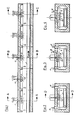
- the tunnel oven shown in Figs. 1, 2, 3 and 4 comprises an enclosure 6 in which the heating and cooling take place.
- This enclosure is divided into five successive zones 1, 2, 3, 4 and 5.
- a mat 7, having the shape of a trellis, moves in the lower part of the enclosure 6 in the direction of the arrow 8.
- This conveyor brings the objects to be heated or cooled, not shown, successively through the zones 1 to 5.
- a fan 9 is mounted, so that it can cause, within the enclosure 6, an ascending gas circulation as indicated by the arrows 10.
- the fan 9 circulates the gases in a closed circuit according to the arrows 10.
- burners 11 intended for heating objects.
- the gases leaving these burners are mixed and entrained by the recirculating air.
- the element of cooling 12 injecting air which is sucked in by fan 9 is shown in FIGS. 3 and 4.
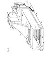
- Fig. 5 is a perspective view (with cutaway) of a modular section of tunnel indicated generally at 13, certain parts being cut away to highlight different details.
- the modular tunnel section 13 essentially comprises a box 14 in the shape of a rectangular parallelepiped lying horizontally on its largest face 15, delimited laterally by the two small faces 16, 17 and above by the large upper face 18. The two small faces of the parallelepiped are not materialized and constitute the bays by which the modular sections of tunnel 13 communicate with each other.
- a conveyor belt 19 runs in the lower part of the modular tunnel section 13; locally only the passage levels 20 and 21 of the upper strand and the lower strand of the carpet are indicated in dotted lines.
- the modular tunnel section 13 is equipped with a set of ramps 22 each of which is provided with an upper flow slot 23.
- the ramps 22 are mutually parallel and at the passage level 20 of the belt 19 and perpendicular to the direction of travel of the latter.
- the ramps 22 open on the outside of the small faces 16 and 17 into supply channels 24 arranged symmetrically on either side of the modular section of tunnel 13 and thereon.
- the large upper face 18 is pierced with a collecting slot 25 which is oriented as are the ramps 22 and collects the air emitted by the latter.
- the collecting slot 25 is capped with a wind box 26 which is itself connected by a converging duct 27 to the inlet of a centrifugal blower 28 disposed above the modular section of tunnel 13 and fixed to it by means not shown in detail.
- the centrifugal blower 28 is actuated by a motor 29.
- the intake of the blower is also provided with an orifice 30 which can be closed by a shutter 31 to adjust or cancel a fresh air intake.
- the outlet 32 of the blower opens into a transverse channel 33 supplying the lateral channels 24.
- the transverse channel 33 is equipped with burners of which only the burner 34 is indicated, serving to heat the air supplied by the blower and brought in through the channels d supply 24 to the ramps 22.
- the assembly with the exception of the blower, its intake and its engine, is housed in an external box 35 of the same general shape as the modular section of tunnel 13 and the intermediate space is occupied by a thermal insulator 36 .
- Fig. 6 shows in a simplified manner a tunnel oven according to the invention composed of five modular sections of tunnel 13; it is a view in longitudinal section along the line G-G of FIG. 9 of the oven thus formed.
- Fig. 7 is a sectional view along the line H-H of FIG. 6 showing the burners 34.
- Fig. 8 is a section along the line E-E of FIG. 6 showing the continuous slit pipes or ramps 22 which ensure the homogeneous distribution of the different air streams.
- Fig. 9 is a sectional view along line F-F of FIG. 6 showing the fresh air intake device of the enclosure.
- the tunnel oven according to the invention therefore comprises a general enclosure 37 in which the heating and / or cooling takes place.
- This general enclosure 37 is divided into five successive zones 38, 39, 40, 41 and 42, each of which is embodied by a modular section of tunnel.
- the conveyor belt 19 in the form of a trellis scrolls in the lower part of the general enclosure 37 in the direction of the arrow 43.
- This carpet 19 scrolls the objects to be heated or cooled (which are not shown) successively in the zones 38 to 42.
- a centrifugal blower 28 delivers air through the transverse channel 33 into the supply channels 24 into which the ramps open 22.
- the air streams emitted uniformly by the ramps 22 are taken up in each zone by a collecting slot 25 and thus return in closed circuit to the channels 24.
- the modular tunnel sections are fitted with burners 34 upstream of the channels 24 so that the combustion gases mix intimately with the circulating air.
- the apparatus of the invention also allows the objects to be treated introduced into the general enclosure 37 to be cooled by diluting the atmosphere of this general enclosure by means of a make-up gas, in particular outside air. aspire to using centrifugal blowers 28 through their orifices 30, the quantity of outside air admitted being regulated by the position of the flaps 31 (FIGS. 5 and 9).
- the burners 34 can obviously be replaced by other devices, for example electric resistors.
- Coils located in the gas circulation circuit and in which a fluid circulates can also be advantageously used.
- the fluid circulating in these coils can be hot or cold.
- the same device can be used both for heating or for cooling the gases circulating in the enclosure of a modular section, depending on the temperature desired for the heat treatment.
- the apparatus of the invention is provided with a regulating device not shown in the figures which makes it possible to choose in a simple manner the temperature curve to obtain the desired heat treatment.
- the regulating device acts on the heating system (supply of the burners, rheostats of the electrical resistances or valves of the coils) when the desired temperature in the section concerned is high (annealing heating), on the other hand when the temperature is relatively lower (cooling) the regulating device acts on the admission of outside air (closable orifices communicating with the outside 30).
- the collecting slot 25 has the effect of bringing together the gas streams in the general form of a set of dihedrons having a common edge, but it goes without saying that it is also possible to produce a modular section of tunnel 13 comprising several collecting slots 25 blocking the gas veins in several dihedrons. In the latter case, the gas streams are more substantially vertical.
- the circulation fan 28 has been shown in the figures describing the apparatus of the invention with a horizontal axis. It goes without saying that the invention is not limited to this embodiment and that the tunnel oven according to the invention can also be equipped with blowers with a vertical axis.
- each of the ramps 22 can be designed in the form of a U-shaped channel open at its upper part and provided with a single slot cap placed on the open part of the U. This system makes it possible to use caps with slots of different widths to also influence the flow through the various ramps.
Abstract
L'invention concerne les enceintes de traitement thermique. Elle a pour objet un four-tunnel qui comprend une enceinte de traitement thermique, un transporteur (19), un système de circulation de gaz et un système de chauffage et/ou de refroidissement du gaz, caractérisé en ce que l'enceinte de traitement thermique est un tunnel où des rampes (22) débitent chacune une ou des veine(s) de gaz ascendante(s), une ou des fentes collectrices supérieures (25), collectent les veines, une ou des soufflantes de circulation (28) reprennent le gaz des veines et le renvoient au circuit de gaz (33, 24, 22) en passant par un ou plusieurs appareils (34) amenant le gaz à la température désirée. Ce four est préféré pour le traitement thermique par convection d'objet distincts.The invention relates to heat treatment chambers. It relates to a tunnel oven which comprises a heat treatment enclosure, a conveyor (19), a gas circulation system and a gas heating and / or cooling system, characterized in that the treatment enclosure thermal is a tunnel where ramps (22) each deliver one or more ascending gas stream (s), one or more upper collector slots (25), collect the veins, one or more circulation blowers (28) resume the gas from the veins and return it to the gas circuit (33, 24, 22) through one or more devices (34) bringing the gas to the desired temperature. This oven is preferred for heat treatment by convection of separate objects.
Description
La présente invention concerne un appareil de traitement thermique tel qu'une arche de recuisson à marche continue pour des corps creux distincts, en particulier pour des produits en verre creux tels des bouteilles, des pots, des bocaux, de la vaisselle, des tubes cathodiques pour T.V. etc...The present invention relates to a heat treatment apparatus such as a continuous annealing arch for separate hollow bodies, in particular for hollow glass products such as bottles, jars, jars, tableware, cathode ray tubes. for TV etc ...
Le traitement thermique, spécialement en vue de la recuisson, des produits en verre creux est réalisé en chauffant ceux-ci à la température de recuit, puis en les refroidissant progressivement. Un tel traitement se fait de manière classique dans un four-tunnel équipé d'un transporteur qui fait défiler les objets à traiter à travers celui-ci.The heat treatment, especially with a view to annealing, of the hollow glass products is carried out by heating them to the annealing temperature, then by gradually cooling them. Such treatment is carried out in a conventional manner in a tunnel oven equipped with a conveyor which scrolls the objects to be treated through it.
Le système apparemment le plus simple pour obtenir un refroidissement progressif est de faire circuler de l'air à contre-courant des corps à traiter en réglant le flux en fonction de la température régnant à un endroit déterminé du four. La pratique a révélé que même en opérant une régulation sur l'entrée de l'air et sur la sortie de celui-ci, on n'obtient pas une homogénéité thermique suffisante.The apparently simplest system for obtaining progressive cooling is to circulate air against the current of the bodies to be treated by regulating the flow as a function of the temperature prevailing at a given location in the oven. Practice has shown that even by regulating the air inlet and the air outlet, one does not obtain sufficient thermal homogeneity.
Un autre procédé consiste à faire passer les objets en verre à traiter à travers un four-tunnel, dans lequel circulent suivant une direction sensiblement verticale des courants de gaz (ou d'air) à la température désirée. Dans ces fours-tunnels, une ou plusieurs files longitudinales de motoventilateurs disposés à la partie supérieure et/ou à la partie inférieure ou bien dans la paroi latérale du tunnel entretiennent une circulation de gaz qui est transversale par rapport au sens de défilement du transporteur portant les objets à traiter.Another method consists in passing the glass objects to be treated through a tunnel oven, in which circulate in a substantially vertical direction streams of gas (or air) at the desired temperature. In these tunnel ovens, one or more longitudinal rows of motor fans arranged at the upper part and / or at the lower part or else in the side wall of the tunnel maintain a gas circulation which is transverse with respect to the direction of travel of the carrier carrying the objects to be treated.
Le gaz ainsi brassé est amené à la température voulue par des dispositifs de chauffage et/ou de refroidissement répartis sur la longueur du tunnel. Le plus souvent, le traitement thermique est un chauffage ou un refroidissement programmé nécessitant un gaz chaud obtenu avec des brûleurs ou des résistances électriques. En règle générale, le gaz circule de bas en haut et le four comporte des zones successives dans chacune desquelles la température est réglable individuellement. Dans certains de ces fours-tunnels, des ventilateurs supérieurs et inférieurs alternent, de sorte que le flux d'air est alternativement ascendant et descendant. Quelques uns de ces fours sont formés de chambres contiguës qui communiquent chacune avec la ou les chambres voisines par une baie ménagée dans la cloison mitoyenne.The gas thus stirred is brought to the desired temperature by heating and / or cooling devices distributed over the length of the tunnel. The more often, the heat treatment is a programmed heating or cooling requiring a hot gas obtained with burners or electric resistances. As a rule, the gas circulates from bottom to top and the oven has successive zones in each of which the temperature is individually adjustable. In some of these tunnel ovens, upper and lower fans alternate, so that the air flow is alternately upward and downward. Some of these ovens are formed by contiguous chambers which each communicate with the neighboring chamber or chambers by a bay provided in the adjoining partition.
Du point de vue de la construction proprement dite, les fours-tunnels des genres ci-dessus sont, en fait, constitués par des gaines co-axiales. La gaine centrale où circule le transporteur est celle dans laquelle les corps traités défilent. De place en place, la gaine centrale comporte des orifices par lesquels les flux d'air sont admis et évacués respectivement. La gaine médiane enveloppe la gaine centrale en ménageant un espace annulaire qui contient les systèmes de circulation et de conduite de l'air, ainsi que les échangeurs de chaleur nécessaires. La gaine extérieure entoure les deux premières en ménageant un second espace annulaire occupé par un isolant thermique. La gaine extérieure et l'isolant thermique peuvent se confondre lorsque l'isolant thermique est autoportant (maçonnerie, pisé, etc...).From the point of view of the construction proper, tunnel furnaces of the above kinds are, in fact, constituted by coaxial sheaths. The central sheath where the conveyor circulates is that in which the treated bodies pass. From place to place, the central sheath has orifices through which the air flows are admitted and evacuated respectively. The central duct surrounds the central duct, creating an annular space which contains the air circulation and ducting systems, as well as the necessary heat exchangers. The outer sheath surrounds the first two, providing a second annular space occupied by a thermal insulator. The outer sheath and the thermal insulation can be confused when the thermal insulation is self-supporting (masonry, adobe, etc.).
En particulier, un exemple de four-tunnel pour le traitement thermique d'objets en verre formé de chambres contiguës est celui qui est décrit dans le brevet des Etats-Unis d'Amérique No. 4.012.190. Ce four-tunnel comporte une enceinte dans laquelle a lieu le traitement thermique. Cette enceinte est divisée en zones successives, traversées par un tapis transporteur en treillis portant les objets et les amenant successivement à travers chacune des zones. Dans la partie supérieure de chaque zone est monté un ventilateur destiné à provoquer une circulation de gaz plus ou moins verticale dans l'enceinte du four-tunnel, et à collecter ce gaz pour l'envoyer ensuite dans un circuit de chauffage et/ou de refroidissement.In particular, an example of a tunnel oven for the heat treatment of glass objects formed from contiguous chambers is that described in US Patent No. 4,012,190. This tunnel oven comprises an enclosure in which the heat treatment takes place. This enclosure is divided into successive zones, crossed by a lattice conveyor belt carrying the objects and bringing them successively through each of the zones. In the upper part of each zone is mounted a fan intended to cause a more or less vertical circulation of gas in the enclosure of the tunnel oven, and to collect this gas in order to then send it into a heating and / or cooling.
L'inconvénient évident d'un four de ce genre est que la température n'y est pas répartie de la façon désirable. En effet, les aspirations axiales créent un flux de gaz convergeant à symétrie de révolution, de sorte que la température n'est pas régulière dans un plan transversal vertical, ce qui a pour conséquence que tous les objets à traiter se trouvant dans une même rangée transversale perpendiculaire au sens du défilement ne subissent pas le même traitement thermique, suivant qu'ils se trouvent au milieu ou sur les côtés du tapis transporteur. En effet les objets situés au milieu du tapis transporteur traversent des courants de gaz ascendants verticaux et subissent ainsi un traitement thermique uniforme. Les objets situés sur les côtés du transporteur par contre, traversent des courants de gaz ascendants d'autant plus obliques qu'ils sont éloignés du milieu du tapis transporteur. Les courants de gaz (obliques) sont provoqués par l'aspiration du ventilateur, situé au milieu de la partie supérieure de chaque zone du four-tunnel et sont d'autant plus obliques que le four-tunnel est large.The obvious disadvantage of such an oven is that the temperature is not distributed there in the desirable manner. Indeed, the axial aspirations create a convergent gas flow with symmetry of revolution, so that the temperature is not regular in a vertical transverse plane, which has the consequence that all the objects to be treated being in the same row transverse perpendicular to the direction of travel do not undergo the same heat treatment, depending on whether they are in the middle or on the sides of the conveyor belt. In fact, the objects located in the middle of the conveyor belt pass through vertical ascending gas currents and thus undergo a uniform heat treatment. Objects located on the sides of the conveyor, on the other hand, pass through ascending gas currents which are all the more oblique the further they are from the middle of the conveyor belt. The gas streams (oblique) are caused by the suction of the fan, located in the middle of the upper part of each zone of the tunnel oven and are all the more oblique the wider the tunnel oven.
Les objets situés sur les côtés du transporteur ne subissent pas par conséquent un traitement thermique uniforme sur toute leur surface extérieure, car, en traversant des courants de gaz ascendants obliques, leur surface ne coupe pas tout entière ces courants de gaz. Il s'en suit un mauvais traitement de recuit et par conséquent des pertes par déchets non négligeables.Objects located on the sides of the conveyor therefore do not undergo a uniform heat treatment over their entire outer surface because, by crossing oblique ascending gas streams, their surface does not entirely cut off these gas streams. It follows bad treatment of annealing and therefore significant waste losses.
Les inconvénients ci-dessus ne sont pas très marqués tant que la largeur du four-tunnel reste relativement faible, mais, comme ces dernières années la tendance est de construire des fours de largeur de plus en plus importante, en vue d'accroître la capacité de traitement, le problème de la répartition transversale uniforme de la température se pose avec plus d'acuité, car les déchets provoqués par un mauvais recuit ont augmenté de façon appréciable avec l'utilisation de fours plus larges.The above drawbacks are not very marked as long as the width of the tunnel oven remains relatively small, but, as in recent years the trend is to build ovens of increasing width, in order to increase the capacity The problem of uniform transverse temperature distribution arises more acutely, since the waste caused by poor annealing has increased appreciably with the use of larger ovens.
Le but de l'invention est de limiter les pertes exagérées provoquées par un mauvais recuit, en soumettant les objets situés sur une même rangée transversale à un même traitement thermique et en leur faisant suivre le même cycle de variation de température sur toute leur surface extérieure. Ainsi, dans un four suivant l'invention, la température considérée sur une coupe transversale à un endroit donné du four doit être uniforme afin d'être la même aux endroits homologues des corps traités et dans les différents corps passant par cet endroit dans le four. Les objets situés sur une même rangée transversale doivent donc suivre le même cycle de traitement thermique, quelle que soit leur position sur le tapis transporteur.The object of the invention is to limit the exaggerated losses caused by poor annealing, by subjecting the objects located on the same transverse row to the same heat treatment and by making them follow the same temperature variation cycle over their entire outer surface. . Thus, in an oven according to the invention, the temperature considered on a cross section at a given location in the oven must be uniform in order to be the same at the homologous locations of the treated bodies and in the various bodies passing through this location in the oven. . Objects located on the same transverse row must therefore follow the same heat treatment cycle, regardless of their position on the conveyor belt.
Pour que le traitement thermique soit convenable, il faut évidemment aussi que la température observée sur une coupe longitudinale respecte un certain profil dont le parcours par les corps à traiter assure le cycle voulu. D'autres critères importants enfin sont la possibilité d'établir et de régler la température à toute valeur désirée en un endroit quelconque du four-tunnel, afin d'adapter le cycle thermique à la nature du produit à traiter, la sûreté de marche, la durabilité de l'installation et l'économie de fonctionnement.For the heat treatment to be suitable, it is obviously also necessary that the temperature observed on a longitudinal section respects a certain profile whose path through the bodies to be treated ensures the desired cycle. Finally, other important criteria are the possibility of establishing and adjusting the temperature to any desired value anywhere in the tunnel oven, in order to adapt the thermal cycle to the nature of the product to be treated, the safety of the durability of the installation and the economy of operation.
L'invention a dès lors pour objet un four-tunnel généralement horizontal pour le traitement thermique, par convection, de corps distincts en verre creux, du type formé par l'assemblage de tronçons modulaires juxtaposés, l'ensemble de ce four-tunnel comprenant une enceinte de traitement thermique, un transporteur à tapis horizontal disposé dans la zone inférieure de l'enceinte et apte à faire défiler les dits corps, un système apte à créer une circulation transversale de gaz entre les corps à traiter, et un système de chauffage et/ou de refroidissement du gaz apte à régler individuellement la température à une valeur désirée dans chacun des tronçons successifs.The subject of the invention is therefore a generally horizontal tunnel oven for the thermal treatment, by convection, of separate hollow glass bodies, of the type formed by the assembly of juxtaposed modular sections, the assembly of this tunnel oven comprising a heat treatment chamber, a horizontal conveyor belt disposed in the lower zone of the chamber and capable of scrolling said bodies, a system capable of creating a transverse circulation of gas between the bodies to be treated, and a heating system and / or gas cooling capable of individually adjusting the temperature to a desired value in each of the successive sections.
Dans le four-tunnel suivant l'invention chacun des tronçons modulaires comporte :
- - des rampes horizontales et parallèles entre elles, occupant toute la largeur de l'enceinte thermique et disposées sous le transporteur parallèlement à celui-ci et perpendiculairement au sens du défilement, aptes à débiter chacune une ou des nappe de gaz ascendant,
- - une ou plusieurs fentes collectrices ménagées dans la paroi supérieure, horizontales et parallèles entre elles, occupant toute la largeur de l'enceinte thermique, disposées perpendiculairement au sens du défilement, aptes à collecter les dites nappes de gaz ascendant,
- - un ou plusieurs dispositifs de chauffage et/ou de refroidissement, apte(s) à amener le gaz collecté à la température désirée dans l'enceinte de traitement thermique du tronçon modulaire concerné,
- - une soufflante de circulation, apte à reprendre le gaz collecté par la ou les fentes collectrices, et à le renvoyer par un circuit de circulation de gaz vers l'ensemble des rampes, en passant par le ou les dispositifs de chauffage et/ou de refroidissement.
- horizontal and parallel ramps between them, occupying the entire width of the thermal enclosure and arranged under the conveyor parallel to the latter and perpendicular to the direction of travel, each capable of delivering one or more layers of rising gas,
- one or more collecting slots made in the upper wall, horizontal and parallel to each other, occupying the entire width of the thermal enclosure, arranged perpendicular to the direction of travel, capable of collecting said layers of ascending gas,
- one or more heating and / or cooling devices capable of bringing the collected gas to the desired temperature in the heat treatment chamber of the modular section concerned,
- - a circulation blower, capable of taking up the gas collected by the collec slot (s) and return it through a gas circulation circuit to all of the ramps, passing through the heating and / or cooling device (s).
Suivant une forme de réalisation particulière, chaque tronçon modulaire est pourvu d'au moins un orifice obturable communiquant avec l'extérieur et apte à amener de l'air extérieur dans le circuit de circulation des gaz; cet orifice obturable est situé en aval des fentes collectrices et en amont de la soufflante de circulation.According to a particular embodiment, each modular section is provided with at least one closable orifice communicating with the outside and capable of bringing outside air into the gas circulation circuit; this closable orifice is located downstream of the collecting slots and upstream of the circulation blower.
Le four-tunnel est pourvu d'un dispositif de régulation apte à agir sur les dispositifs de chauffage et/ou de refroidissement de chaque tronçon modulaire pour amener et maintenir le gaz collecté à la température désirée dans l'enceinte de traitement thermique du tronçon modulaire concerné.The tunnel oven is provided with a regulating device capable of acting on the heating and / or cooling devices of each modular section in order to bring and maintain the collected gas at the desired temperature in the enclosure for thermal treatment of the modular section. concerned.
Suivant une forme de réalisation avantageuse, les rampes débitant les nappes de gaz ascendant sont des tubes qui comportent une ou des ouvertures de débit à leur partie supérieure et qui sont alimentées à leurs extrémités par des canaux d'amenée de gaz.According to an advantageous embodiment, the ramps discharging the ascending layers of gas are tubes which have one or more flow openings at their upper part and which are supplied at their ends by gas supply channels.
Dans les différentes formes de réalisation ci-dessus, la soufflante de circulation est alimentée par une boîte à vent dans laquelle débouchent les fentes collectrices qui collectent le gaz.In the various embodiments above, the circulation blower is supplied by a wind box into which open the collecting slots which collect the gas.
Suivant une forme de réalisation particulière, chaque tronçon modulaire est muni de deux canaux d'amenée de gaz établis de part et d'autre de celui-ci qui alimentent les rampes en gaz propulsé au moyen de la soufflante de circulation, celle-ci débitant le gaz dans les canaux par un canal transversal commun.According to a particular embodiment, each modular section is provided with two gas supply channels established on either side thereof which supply the ramps with propelled gas by means of the circulation blower, the latter delivering gas in the channels through a common cross channel.
Dans les dessins annexés :
- Fig. 1 à 4 illustrent un four connu ;
- Fig. 5 à 9 illustrent un four conforme à l'invention.
- Fig. 1 to 4 illustrate a known oven;
- Fig. 5 to 9 illustrate an oven according to the invention.
Pour faciliter les comparaisons, on trouvera ci-après la description, faite avec référence aux dessins annexés, d'un four actuellement en vente.
- La Fig. 1 représente une coupe longitudinale suivant la ligne D-D de la Fig. 2 d'un four à convection que l'on rencontre actuellement sur le marché.
- La Fig. 2 est une vue en coupe suivant la ligne A-A de la Fig. 1, dans laquelle figurent les éléments de chauffage.
- La Fig. 3 est une vue en coupe suivant la ligne B-B de la Fig. 1, dans laquelle figurent les éléments de chauffage et de refroidissement.
- La Fig. 4 est une vue en coupe suivant la ligne C-C de la Fig. 1, dans laquelle ne figurent que les éléments de refroidissement.
- Fig. 1 represents a longitudinal section along the line DD of FIG. 2 of a convection oven that is currently found on the market.
- Fig. 2 is a sectional view along line AA of FIG. 1, in which the heating elements appear.
- Fig. 3 is a sectional view along line BB of FIG. 1, in which the heating and cooling elements appear.
- Fig. 4 is a sectional view along the line CC of FIG. 1, in which only the cooling elements appear.
Le four-tunnel représenté aux Fig. 1, 2, 3 et 4 comprend une enceinte 6 dans laquelle ont lieu le chauffage et le refroidissement. Cette enceinte est répartie en cinq zones successives 1, 2, 3, 4 et 5. Un tapis 7, ayant la forme d'un treillis, se déplace dans la partie inférieure de l'enceinte 6 dans le sens de la flèche 8. Ce tapis amène les objets à chauffer ou à refroidir, non représentés, successivement à travers les zones 1 à 5. Dans la partie supérieure de chacune des zones, est monté un ventilateur 9, de telle façon qu'il puisse provoquer, dans l'enceinte 6, une circula tion de gaz ascendante comme indiqué par les flèches 10.The tunnel oven shown in Figs. 1, 2, 3 and 4 comprises an
Le ventilateur 9 fait circuler les gaz en un circuit fermé suivant les flèches 10. Dans la partie supérieure et dans les canaux latéraux, sont monté des brûleurs 11 destinés au chauffage des objets. Les gaz sortant de ces brûleurs sont mélangés et entraînés par l'air de recirculation. L'élément de refroidissement 12 injectant de l'air qui est aspiré par le ventilateur 9 est représenté sur les Fig. 3 et 4.The
L'inconvénient évident d'un four de ce genre est que la température n'y est pas répartie de la façon désirable. En effet, les aspirations axiales créent un flux d'air convergent à symétrie de révolution, de sorte que la température n'est pas régulière dans un plan transversal vertical. Du fait de cette imperfection il est impossible de faire parcourir par l'ensemble de la charge le cycle thermique nécessaire.The obvious disadvantage of such an oven is that the temperature is not distributed there in the desirable manner. Indeed, the axial aspirations create a convergent air flow with symmetry of revolution, so that the temperature is not regular in a vertical transverse plane. Due to this imperfection, it is impossible for the entire load to go through the necessary thermal cycle.
Un four-tunnel modulaire conforme à l'invention est décrit spécifiquement ci-après avec référence aux Fig. 5 à 9.A modular tunnel oven in accordance with the invention is described specifically below with reference to FIGS. 5 to 9.
La Fig. 5 est une vue en perspective (avec arrachements) d'un tronçon modulaire de tunnel indiqué de manière générale en 13, certaines parties étant arrachées pour la mise en évidence de différents détails. Le tronçon modulaire de tunnel 13 comprend essentiellement un caisson 14 en forme de parallélipipède rectangle couché horizontalement sur sa plus grande face 15, délimité latéralement par les deux petites faces 16, 17 et au-dessus par la grande face supérieure 18. Les deux petites faces du parallélipipède ne sont pas matérialisées et constituent les baies par lesquelles les tronçons modulaires de tunnel 13 communiquent les uns avec les autres. Un transporteur à tapis 19 défile dans la partie inférieure du tronçon modulaire de tunnel 13; localement seuls les niveaux de passage 20 et 21 du brin supérieur et du brin inférieur du tapis sont indiqués en pointillés. Le tronçon modulaire de tunnel 13 est équipé d'un jeu de rampes 22 dont chacune est munie d'une fente de débit supérieure 23. Les rampes 22 sont parallèles entre elles et au niveau de passage 20 du tapis 19 et perpendiculaires au sens de défilement de ce dernier. Les rampes 22 débouchent à l'extérieur des petites faces 16 et 17 dans des canaux d'alimentation 24 disposés symétriquement de part et d'autre du tronçon modulaire de tunnel 13 et sur celui- ci. La grande face supérieure 18 est percée d'une fente collectrice 25 qui est orientée comme le sont les rampes 22 et collecte l'air émis par ces dernières. La fente collectrice 25 est coiffée d'une boîte à vent 26 qui est elle-même raccordée par un conduit convergent 27 à l'admission d'une soufflante centrifuge 28 disposée au-dessus du tronçon modulaire de tunnel 13 et fixée à celui-ci par des moyens non représentés en détail. La soufflante centrifuge 28 est actionnée par un moteur 29. L'admission de la soufflante est également munie d'un orifice 30 pouvant être obturé par un volet 31 pour régler ou annuler une admission d'air frais. La sortie 32 de la soufflante débouche dans un canal transversal 33 alimentant les canaux latéraux 24. Le canal transversal 33 est équipé de brûleurs dont seul le brûleur 34 est indiqué, servant à réchauffer l'air débité par la soufflante et amené par les canaux d'alimentation 24 aux rampes 22.Fig. 5 is a perspective view (with cutaway) of a modular section of tunnel indicated generally at 13, certain parts being cut away to highlight different details. The
L'ensemble, à l'exception de la soufflante, de son admission et de son moteur, est abrité dans un caisson extérieur 35 de même forme générale que le tronçon modulaire de tunnel 13 et l'espace intermédiaire est occupé par un isolant thermique 36.The assembly, with the exception of the blower, its intake and its engine, is housed in an
La Fig. 6 représente de manière simplifiée un four-tunnel conforme à l'invention composé de cinq tronçons modulaires de tunnel 13; elle est une vue en coupe longitudinale suivant la ligne G-G de la Fig. 9 du four ainsi constitué.Fig. 6 shows in a simplified manner a tunnel oven according to the invention composed of five modular sections of
La Fig. 7 est une vue en coupe suivant la ligne H-H de la Fig. 6 montrant les brûleurs 34.Fig. 7 is a sectional view along the line H-H of FIG. 6 showing the
La Fig. 8 est une en coupe suivant la ligne E-E de la Fig. 6 montrant les tuyaux à fente continue ou rampes 22 qui assurent la répartition homogène des différentes veines d'air.Fig. 8 is a section along the line E-E of FIG. 6 showing the continuous slit pipes or
La Fig. 9 est une vue en coupe suivant la ligne F-F de la Fig. 6 montrant le dispositif d'aspiration d'air frais de l'enceinte.Fig. 9 is a sectional view along line F-F of FIG. 6 showing the fresh air intake device of the enclosure.
Le four-tunnel conforme à l'invention (voir Fig. 6 et 7) comprend, par conséquent, une enceinte générale 37 dans laquelle ont lieu le chauffage et/ou le refroidissement. Cette enceinte générale 37 est répartie en cinq zones successives 38, 39, 40, 41 et 42, dont chacune est matérialisée par un tronçon modulaire de tunnel. Le transporteur à tapis 19 sous forme de treillis défile dans la partie inférieure de l'enceinte générale 37 dans le sens de la flèche 43. Ce tapis 19 fait défiler les objets à chauffer ou refroidir (qui ne sont pas représentés) successivement dans les zones 38 à 42. Il est ainsi apparent que, dans chacune des zones, une soufflante centrifuge 28 refoule l'air par le canal transversal 33 dans les canaux d'alimentation 24 dans lesquels débouchent les rampes 22. Les veines d'air émises uniformément par les rampes 22 sont reprises dans chaque zone par une fente collectrice 25 et retournent ainsi en circuit fermé aux canaux 24.The tunnel oven according to the invention (see FIGS. 6 and 7) therefore comprises a
Dans les zones de chauffage, les tronçons modulaires de tunnel sont équipés de brûleurs 34 en amont des canaux 24 de manière que les gaz de combustion se mélangent intimement à l'air en circulation.In the heating zones, the modular tunnel sections are fitted with
L'appareil de l'invention permet également que les objets à traiter introduits dans l'enceinte générale 37 soient refroidis par dilution de l'atmosphère de cette enceinte générale au moyen d'un gaz d'appoint, en particulier de l'air extérieur aspiré à l'aide des soufflantes centrifuges 28 par leurs orifices 30, la quantité d'air extérieur admise étant réglée par la position des volets 31 (Fig. 5 et 9).The apparatus of the invention also allows the objects to be treated introduced into the
Les brûleurs 34 peuvent évidemment être remplacés par d'autres appareils, par exemple des résistances électriques.The
Des serpentins situés dans le circuit de circulation des gaz et dans lesquels circule un fluide peuvent également être utilisés avantageusement. En effet selon les besoins, le fluide circulant dans ces serpentins peut être chaud ou froid. Ainsi un même dispositif peut servir à la fois pour le chauffage ou pour le refroidissement des gaz circulant dans l'enceinte d'un tronçon modulaire, suivant la température voulue pour le traitement thermique.Coils located in the gas circulation circuit and in which a fluid circulates can also be advantageously used. In fact, as required, the fluid circulating in these coils can be hot or cold. Thus the same device can be used both for heating or for cooling the gases circulating in the enclosure of a modular section, depending on the temperature desired for the heat treatment.
L'appareil de l'invention est pourvu d'un dispositif de régulation non représenté dans les figures qui permet de choisir de faç.on simple la courbe de température pour obtenir le traitement thermique voulu. Ainsi pour chacun des tronçons le dispositif de régulation agit sur le système de chauffage (alimentation des brûleurs, rhéostats des résistances électriques ou vannes des serpentins) lorsque la température désirée dans le tronçon concerné est élevée (chauffage de recuit), par contre lorsque la température est relativement plus basse (refroidissement) le dispositif de régulation agit sur l'admission de l'air extérieur (orifices obturables communiquant avec l'extérieur 30).The apparatus of the invention is provided with a regulating device not shown in the figures which makes it possible to choose in a simple manner the temperature curve to obtain the desired heat treatment. Thus for each of the sections, the regulating device acts on the heating system (supply of the burners, rheostats of the electrical resistances or valves of the coils) when the desired temperature in the section concerned is high (annealing heating), on the other hand when the temperature is relatively lower (cooling) the regulating device acts on the admission of outside air (closable orifices communicating with the outside 30).
D'autre part, la fente collectrice 25 a pour effet de rassembler les veines de gaz à la forme générale d'un jeu de dièdres présentant une arête commune, mais il va de soi qu'il est également possible de réaliser un tronçon modulaire de tunnel 13 comportant plusieurs fentes collectrices 25 rassemblant les veines de gaz en plusieurs dièdres. Dans ce dernier cas, les veines de gaz sont plus sensiblement verticales.On the other hand, the collecting
La soufflante de circulation 28 a été représentée dans les figures décrivant l'appareil de l'invention avec un axe horizontal. Il va de soi que l'invention ne se limite pas à cette forme de réalisation et que le four-tunnel suivant l'invention peut également être équipé de soufflantes à axe vertical.The
Certains détails de réalisation qui ne sont pas indispensables à la compréhension du principe de l'invention n'ont pas été représentés, par exemple les canaux d'alimentation 24 peuvent abriter des déflecteurs permettant d'ajuster à volonté le flux d'air par chacune des rampes 22. En variante, chacune des rampes 22 peut être conçue sous la forme d'un canal en U ouvert à sa partie supérieure et muni d'une coiffe à fente unique posée sur la partie ouverte du U. Ce système permet d'utiliser des coiffes munies de fentes de différentes largeurs pour influencer également le débit par les diverses rampes.Certain construction details which are not essential for understanding the principle of the invention have not been shown, for example the
Claims (6)
Priority Applications (1)
| Application Number | Priority Date | Filing Date | Title |
|---|---|---|---|
| AT83870033T ATE20619T1 (en) | 1982-03-25 | 1983-03-24 | DEVICE FOR THERMAL TREATMENT OF OBJECTS BY CONVECTION. |
Applications Claiming Priority (2)
| Application Number | Priority Date | Filing Date | Title |
|---|---|---|---|
| FR8205087A FR2524131A1 (en) | 1982-03-25 | 1982-03-25 | APPARATUS FOR THERMALLY PROCESSING OBJECTS BY CONVECTION |
| FR8205087 | 1982-03-25 |
Publications (2)
| Publication Number | Publication Date |
|---|---|
| EP0090790A1 true EP0090790A1 (en) | 1983-10-05 |
| EP0090790B1 EP0090790B1 (en) | 1986-07-02 |
Family
ID=9272382
Family Applications (1)
| Application Number | Title | Priority Date | Filing Date |
|---|---|---|---|
| EP83870033A Expired EP0090790B1 (en) | 1982-03-25 | 1983-03-24 | Apparatus for the heat treatment of articles by convection |
Country Status (6)
| Country | Link |
|---|---|
| US (1) | US4534780A (en) |
| EP (1) | EP0090790B1 (en) |
| AT (1) | ATE20619T1 (en) |
| DE (1) | DE3364337D1 (en) |
| ES (1) | ES8401793A1 (en) |
| FR (1) | FR2524131A1 (en) |
Cited By (5)
| Publication number | Priority date | Publication date | Assignee | Title |
|---|---|---|---|---|
| EP0334556A1 (en) * | 1988-03-21 | 1989-09-27 | Metritherm Furnace Systems Limited | Improvements relating to furnaces |
| FR2630199A1 (en) * | 1988-04-19 | 1989-10-20 | Stein Heurtey | Installation for heat treatment by convection, particularly of components intended for the automobile industry |
| EP0492423A2 (en) * | 1990-12-24 | 1992-07-01 | Dornier Gmbh | Method for burning explosive substances |
| EP1050731A1 (en) * | 1999-05-03 | 2000-11-08 | EISENMANN MASCHINENBAU KG (Komplementär: EISENMANN-Stiftung) | Firing furnace |
| WO2018149822A1 (en) * | 2017-02-17 | 2018-08-23 | Vkr Holding A/S | Thermal treatment of pane elements for vacuum insulating glass units |
Families Citing this family (17)
| Publication number | Priority date | Publication date | Assignee | Title |
|---|---|---|---|---|
| US4620864A (en) * | 1984-07-23 | 1986-11-04 | Glasstech, Inc. | Glass sheet tempering utilizing heating and quenching performed in ambient at superatmospheric pressure |
| US4681616A (en) * | 1985-07-15 | 1987-07-21 | Glasstech, Inc. | Glass sheet tempering method and furnace |
| US4781747A (en) * | 1987-08-17 | 1988-11-01 | Glasstech International L.P. | Blow back control device in glass tempering system |
| DE8915647U1 (en) * | 1989-03-21 | 1990-12-13 | Reinbold, Heinz, Dipl.-Ing., 5200 Siegburg, De | |
| ES2113263B1 (en) * | 1994-08-01 | 1999-01-01 | Barragan Amelia Gomez | CONTINUOUS LONGITUDINAL OVEN FOR DRYING AND VULCANIZING OF RUBBER PROFILES. |
| DE19721334C2 (en) * | 1997-05-22 | 1999-07-29 | Horn Glasanlagenbau Gmbh & Co | Cooling track, especially for cooling glass objects |
| US6394794B2 (en) * | 2000-02-02 | 2002-05-28 | Btu International, Inc. | Modular furnace system |
| DE10046957A1 (en) * | 2000-09-21 | 2002-04-11 | Basf Ag | Process for producing a multimetal oxide catalyst, process for producing unsaturated aldehydes and / or carboxylic acids and band calciner |
| EP1421035A1 (en) * | 2001-07-11 | 2004-05-26 | Feracitas Oy | Method for conducting heat to a glass sheet |
| DE10211446A1 (en) * | 2002-03-15 | 2003-10-02 | Basf Ag | Process for the preparation of a catalyst containing vanadium, phosphorus and oxygen |
| US7155876B2 (en) | 2003-05-23 | 2007-01-02 | Douglas Machine, Inc. | Heat tunnel for film shrinking |
| FI120451B (en) * | 2003-06-24 | 2009-10-30 | Uniglass Engineering Oy | Method and apparatus for heating glass |
| DE102007057237A1 (en) * | 2007-11-26 | 2009-05-28 | Umicore Ag & Co. Kg | Tunnel kiln for the temperature treatment of goods |
| US20140261974A1 (en) * | 2013-03-14 | 2014-09-18 | Southwall Technologies, Inc. | In-Line Tunnel Oven and Method for Treating Insulating Glass Units |
| US20150118632A1 (en) * | 2013-10-31 | 2015-04-30 | Mingsheng Liu | Industrial Conveyor Oven |
| US9663393B2 (en) | 2015-09-01 | 2017-05-30 | Owens-Brockway Glass Container Inc. | Process and apparatus for coloring glass containers |
| FI128655B (en) | 2019-03-21 | 2020-09-30 | Glaston Finland Oy | Tempering furnace for glass sheets |
Citations (6)
| Publication number | Priority date | Publication date | Assignee | Title |
|---|---|---|---|---|
| FR1393921A (en) * | 1964-05-15 | 1965-03-26 | Ofenbau Fritz G M B H & Co K G | Device for reducing internal stresses in reinforcing steel mesh for reinforced concrete |
| FR2197456A5 (en) * | 1972-08-17 | 1974-03-22 | Cepi | Tunnel furnace heated by ascending gas - from a duct beneath the hearth |
| DE2518007A1 (en) * | 1974-04-25 | 1975-11-13 | Roper Corp | OVEN SYSTEM FOR CONTINUOUS THERMAL TREATMENT OF A MATERIAL |
| US4012190A (en) * | 1975-09-15 | 1977-03-15 | E. W. Bowman Incorporated | Annealing lehr |
| FR2420109A2 (en) * | 1978-03-13 | 1979-10-12 | Machinery International Ltd Bk | Heat treatment oven for workpiece giving off coating solvent - has several zones from which gases are removed continuously, and incinerator at upstream zone |
| US4298341A (en) * | 1980-03-21 | 1981-11-03 | Nowack William C | Industrial oven having air recirculating means for minimizing heat loss |
Family Cites Families (5)
| Publication number | Priority date | Publication date | Assignee | Title |
|---|---|---|---|---|
| US2045259A (en) * | 1933-04-24 | 1936-06-23 | George W Batchell | Leer |
| US2725680A (en) * | 1953-07-17 | 1955-12-06 | Pittsburgh Corning Corp | Annealing lehr |
| US2982052A (en) * | 1955-07-28 | 1961-05-02 | British Hartford Fairmont Ltd | Lehrs for glassware |
| US3778245A (en) * | 1970-12-22 | 1973-12-11 | Maul Bros Inc | Method and apparatus for heat treating glassware |
| FR2456715A1 (en) * | 1979-05-16 | 1980-12-12 | Stein Surface | METHOD FOR ADJUSTING THE TEMPERATURE OF THE GLASS IN A CLOTHING RACK AND A CLOTHING RACK FOR THE IMPLEMENTATION OF THIS METHOD |
-
1982
- 1982-03-25 FR FR8205087A patent/FR2524131A1/en not_active Withdrawn
-
1983
- 1983-03-15 US US06/475,549 patent/US4534780A/en not_active Expired - Fee Related
- 1983-03-24 DE DE8383870033T patent/DE3364337D1/en not_active Expired
- 1983-03-24 AT AT83870033T patent/ATE20619T1/en not_active IP Right Cessation
- 1983-03-24 EP EP83870033A patent/EP0090790B1/en not_active Expired
- 1983-03-25 ES ES521007A patent/ES8401793A1/en not_active Expired
Patent Citations (6)
| Publication number | Priority date | Publication date | Assignee | Title |
|---|---|---|---|---|
| FR1393921A (en) * | 1964-05-15 | 1965-03-26 | Ofenbau Fritz G M B H & Co K G | Device for reducing internal stresses in reinforcing steel mesh for reinforced concrete |
| FR2197456A5 (en) * | 1972-08-17 | 1974-03-22 | Cepi | Tunnel furnace heated by ascending gas - from a duct beneath the hearth |
| DE2518007A1 (en) * | 1974-04-25 | 1975-11-13 | Roper Corp | OVEN SYSTEM FOR CONTINUOUS THERMAL TREATMENT OF A MATERIAL |
| US4012190A (en) * | 1975-09-15 | 1977-03-15 | E. W. Bowman Incorporated | Annealing lehr |
| FR2420109A2 (en) * | 1978-03-13 | 1979-10-12 | Machinery International Ltd Bk | Heat treatment oven for workpiece giving off coating solvent - has several zones from which gases are removed continuously, and incinerator at upstream zone |
| US4298341A (en) * | 1980-03-21 | 1981-11-03 | Nowack William C | Industrial oven having air recirculating means for minimizing heat loss |
Cited By (8)
| Publication number | Priority date | Publication date | Assignee | Title |
|---|---|---|---|---|
| EP0334556A1 (en) * | 1988-03-21 | 1989-09-27 | Metritherm Furnace Systems Limited | Improvements relating to furnaces |
| FR2630199A1 (en) * | 1988-04-19 | 1989-10-20 | Stein Heurtey | Installation for heat treatment by convection, particularly of components intended for the automobile industry |
| EP0492423A2 (en) * | 1990-12-24 | 1992-07-01 | Dornier Gmbh | Method for burning explosive substances |
| EP0492423A3 (en) * | 1990-12-24 | 1992-11-19 | Dornier Gmbh | Method for burning explosive substances |
| EP1050731A1 (en) * | 1999-05-03 | 2000-11-08 | EISENMANN MASCHINENBAU KG (Komplementär: EISENMANN-Stiftung) | Firing furnace |
| WO2018149822A1 (en) * | 2017-02-17 | 2018-08-23 | Vkr Holding A/S | Thermal treatment of pane elements for vacuum insulating glass units |
| EP3608497A1 (en) * | 2017-02-17 | 2020-02-12 | VKR Holding A/S | Thermal treatment of pane elements for vacuum insulating glass units |
| US10640412B2 (en) | 2017-02-17 | 2020-05-05 | Vkr Holding A/S | Thermal treatment of pane elements for vacuum insulating glass units |
Also Published As
| Publication number | Publication date |
|---|---|
| US4534780A (en) | 1985-08-13 |
| ES521007A0 (en) | 1984-01-01 |
| DE3364337D1 (en) | 1986-08-07 |
| ES8401793A1 (en) | 1984-01-01 |
| EP0090790B1 (en) | 1986-07-02 |
| FR2524131A1 (en) | 1983-09-30 |
| ATE20619T1 (en) | 1986-07-15 |
Similar Documents
| Publication | Publication Date | Title |
|---|---|---|
| EP0090790B1 (en) | Apparatus for the heat treatment of articles by convection | |
| EP0106758B1 (en) | Apparatus to assist in the support of a glass sheet brought to its deformation temperature, the sheet being simultaneously supported by mechanical means | |
| EP2191953B1 (en) | Oven for the thermal conditioning of preforms, comprising a ventilation plenum | |
| EP2342065B1 (en) | Improved oven for the thermal conditioning of preforms made of a thermoplastic material | |
| FR2716635A1 (en) | Laboratory oven cabinet including refrigerated cabinet with temperature balancing cabinet. | |
| CA3035837C (en) | Cooking module for a linear tunnel oven for bakery products, pastries and the like, and linear tunnel oven comprising at least one such module | |
| CA2334994C (en) | Rotary furnace with tubular central flow | |
| EP3601624B1 (en) | Section and method for cooling a continuous line combining dry cooling and wet cooling. | |
| FR2483178A1 (en) | Bakery oven using reversible flow heating air - which is always directed diagonally upwards through prod. to be baked | |
| EP1133666B1 (en) | Device for high temperature heat treatment of ligneous material | |
| EP0371845B1 (en) | Controlled proofing chamber, especially for making pastry and for bakery | |
| EP2200946B1 (en) | Tempering furnace and method comprising several devices for blowing a fluid on the face of a thin member of the glazing type | |
| FR2618300A1 (en) | METHOD FOR CONDUCTING AN INCUBATOR FOR EGGS AND INCUBATOR FOR ITS IMPLEMENTATION | |
| EP3012565A1 (en) | Drying tunnel for ceramic products | |
| FR2534452A1 (en) | HOT AIR RECYCLING OVEN FOR COOKED PRODUCTS | |
| EP1216129B1 (en) | Gas oven for continuous curing in particular rubber products | |
| CH354047A (en) | Baking oven | |
| FR2535578A1 (en) | Improved baking oven intended in particular for the food industry | |
| EP0940372A2 (en) | Apparatus for thermal treatment of glass sheets | |
| FR2632714A1 (en) | Hot air drying furnace for dehydrating fruit or vegetables laid down on carriages with superimposed metal trays, particularly for turning green plums into prunes | |
| BE705875A (en) | ||
| FR2588068A1 (en) | Conveyor-belt dryer | |
| FR2754144A1 (en) | Modular, linear cooking oven for rapid, continuous food cooking | |
| FR2973100A1 (en) | AIR FLOW DIFFUSION INSTALLATION | |
| WO2006075076A1 (en) | Gas baking furnace for rubber products |
Legal Events
| Date | Code | Title | Description |
|---|---|---|---|
| PUAI | Public reference made under article 153(3) epc to a published international application that has entered the european phase |
Free format text: ORIGINAL CODE: 0009012 |
|
| AK | Designated contracting states |
Kind code of ref document: A1 Designated state(s): AT BE CH DE FR GB IT LI LU NL SE |
|
| 17P | Request for examination filed |
Effective date: 19831119 |
|
| RAP1 | Party data changed (applicant data changed or rights of an application transferred) |
Owner name: SOCIETE D'ETUDES ET INSTALLATIONS INDUSTRIELLES CN |
|
| GRAA | (expected) grant |
Free format text: ORIGINAL CODE: 0009210 |
|
| AK | Designated contracting states |
Kind code of ref document: B1 Designated state(s): AT BE CH DE FR GB IT LI LU NL SE |
|
| REF | Corresponds to: |
Ref document number: 20619 Country of ref document: AT Date of ref document: 19860715 Kind code of ref document: T |
|
| ITF | It: translation for a ep patent filed |
Owner name: JACOBACCI & PERANI S.P.A. |
|
| REF | Corresponds to: |
Ref document number: 3364337 Country of ref document: DE Date of ref document: 19860807 |
|
| PLBE | No opposition filed within time limit |
Free format text: ORIGINAL CODE: 0009261 |
|
| STAA | Information on the status of an ep patent application or granted ep patent |
Free format text: STATUS: NO OPPOSITION FILED WITHIN TIME LIMIT |
|
| 26N | No opposition filed | ||
| PGFP | Annual fee paid to national office [announced via postgrant information from national office to epo] |
Ref country code: BE Payment date: 19920102 Year of fee payment: 10 |
|
| PGFP | Annual fee paid to national office [announced via postgrant information from national office to epo] |
Ref country code: GB Payment date: 19920205 Year of fee payment: 10 |
|
| PGFP | Annual fee paid to national office [announced via postgrant information from national office to epo] |
Ref country code: SE Payment date: 19920206 Year of fee payment: 10 Ref country code: CH Payment date: 19920206 Year of fee payment: 10 |
|
| PGFP | Annual fee paid to national office [announced via postgrant information from national office to epo] |
Ref country code: FR Payment date: 19920219 Year of fee payment: 10 |
|
| PGFP | Annual fee paid to national office [announced via postgrant information from national office to epo] |
Ref country code: AT Payment date: 19920310 Year of fee payment: 10 |
|
| PGFP | Annual fee paid to national office [announced via postgrant information from national office to epo] |
Ref country code: LU Payment date: 19920320 Year of fee payment: 10 |
|
| ITTA | It: last paid annual fee | ||
| PGFP | Annual fee paid to national office [announced via postgrant information from national office to epo] |
Ref country code: NL Payment date: 19920331 Year of fee payment: 10 |
|
| PGFP | Annual fee paid to national office [announced via postgrant information from national office to epo] |
Ref country code: DE Payment date: 19920505 Year of fee payment: 10 |
|
| EPTA | Lu: last paid annual fee | ||
| PG25 | Lapsed in a contracting state [announced via postgrant information from national office to epo] |
Ref country code: LU Free format text: LAPSE BECAUSE OF NON-PAYMENT OF DUE FEES Effective date: 19930324 Ref country code: GB Effective date: 19930324 Ref country code: AT Effective date: 19930324 |
|
| PG25 | Lapsed in a contracting state [announced via postgrant information from national office to epo] |
Ref country code: SE Effective date: 19930325 |
|
| PG25 | Lapsed in a contracting state [announced via postgrant information from national office to epo] |
Ref country code: LI Effective date: 19930331 Ref country code: CH Effective date: 19930331 Ref country code: BE Effective date: 19930331 |
|
| BERE | Be: lapsed |
Owner name: SOC. D'ETUDES ET INSTALLATIONS INDUSTRIELLES CNUD Effective date: 19930331 |
|
| PG25 | Lapsed in a contracting state [announced via postgrant information from national office to epo] |
Ref country code: NL Effective date: 19931001 |
|
| NLV4 | Nl: lapsed or anulled due to non-payment of the annual fee | ||
| GBPC | Gb: european patent ceased through non-payment of renewal fee |
Effective date: 19930324 |
|
| PG25 | Lapsed in a contracting state [announced via postgrant information from national office to epo] |
Ref country code: FR Effective date: 19931130 |
|
| REG | Reference to a national code |
Ref country code: CH Ref legal event code: PL |
|
| PG25 | Lapsed in a contracting state [announced via postgrant information from national office to epo] |
Ref country code: DE Effective date: 19931201 |
|
| REG | Reference to a national code |
Ref country code: FR Ref legal event code: ST |
|
| EUG | Se: european patent has lapsed |
Ref document number: 83870033.4 Effective date: 19931008 |