EP2200946B1 - Tempering furnace and method comprising several devices for blowing a fluid on the face of a thin member of the glazing type - Google Patents
Tempering furnace and method comprising several devices for blowing a fluid on the face of a thin member of the glazing type Download PDFInfo
- Publication number
- EP2200946B1 EP2200946B1 EP08837682A EP08837682A EP2200946B1 EP 2200946 B1 EP2200946 B1 EP 2200946B1 EP 08837682 A EP08837682 A EP 08837682A EP 08837682 A EP08837682 A EP 08837682A EP 2200946 B1 EP2200946 B1 EP 2200946B1
- Authority
- EP
- European Patent Office
- Prior art keywords
- blowing
- axis
- central horizontal
- fan
- horizontal axis
- Prior art date
- Legal status (The legal status is an assumption and is not a legal conclusion. Google has not performed a legal analysis and makes no representation as to the accuracy of the status listed.)
- Active
Links
Images


Classifications
-
- C—CHEMISTRY; METALLURGY
- C03—GLASS; MINERAL OR SLAG WOOL
- C03B—MANUFACTURE, SHAPING, OR SUPPLEMENTARY PROCESSES
- C03B27/00—Tempering or quenching glass products
- C03B27/04—Tempering or quenching glass products using gas
- C03B27/0404—Nozzles, blow heads, blowing units or their arrangements, specially adapted for flat or bent glass sheets
-
- C—CHEMISTRY; METALLURGY
- C03—GLASS; MINERAL OR SLAG WOOL
- C03B—MANUFACTURE, SHAPING, OR SUPPLEMENTARY PROCESSES
- C03B25/00—Annealing glass products
- C03B25/04—Annealing glass products in a continuous way
- C03B25/06—Annealing glass products in a continuous way with horizontal displacement of the glass products
- C03B25/08—Annealing glass products in a continuous way with horizontal displacement of the glass products of glass sheets
-
- C—CHEMISTRY; METALLURGY
- C03—GLASS; MINERAL OR SLAG WOOL
- C03B—MANUFACTURE, SHAPING, OR SUPPLEMENTARY PROCESSES
- C03B27/00—Tempering or quenching glass products
- C03B27/04—Tempering or quenching glass products using gas
- C03B27/0404—Nozzles, blow heads, blowing units or their arrangements, specially adapted for flat or bent glass sheets
- C03B27/0408—Nozzles, blow heads, blowing units or their arrangements, specially adapted for flat or bent glass sheets being dismountable
-
- C—CHEMISTRY; METALLURGY
- C03—GLASS; MINERAL OR SLAG WOOL
- C03B—MANUFACTURE, SHAPING, OR SUPPLEMENTARY PROCESSES
- C03B27/00—Tempering or quenching glass products
- C03B27/04—Tempering or quenching glass products using gas
- C03B27/044—Tempering or quenching glass products using gas for flat or bent glass sheets being in a horizontal position
-
- C—CHEMISTRY; METALLURGY
- C03—GLASS; MINERAL OR SLAG WOOL
- C03B—MANUFACTURE, SHAPING, OR SUPPLEMENTARY PROCESSES
- C03B29/00—Reheating glass products for softening or fusing their surfaces; Fire-polishing; Fusing of margins
- C03B29/04—Reheating glass products for softening or fusing their surfaces; Fire-polishing; Fusing of margins in a continuous way
- C03B29/06—Reheating glass products for softening or fusing their surfaces; Fire-polishing; Fusing of margins in a continuous way with horizontal displacement of the products
- C03B29/08—Glass sheets
-
- F—MECHANICAL ENGINEERING; LIGHTING; HEATING; WEAPONS; BLASTING
- F27—FURNACES; KILNS; OVENS; RETORTS
- F27D—DETAILS OR ACCESSORIES OF FURNACES, KILNS, OVENS, OR RETORTS, IN SO FAR AS THEY ARE OF KINDS OCCURRING IN MORE THAN ONE KIND OF FURNACE
- F27D7/00—Forming, maintaining, or circulating atmospheres in heating chambers
- F27D7/04—Circulating atmospheres by mechanical means
Definitions
- the present invention relates to a quenching furnace comprising several devices for blowing a fluid on at least one face of a thin glazing element.
- Such a blowing device is used in the glass industry for bending and / or tempering glazing.
- This device comprises, in a usual way inside an enclosure having a central horizontal axis corresponding to the central axis of travel of the thin element, a radial flow fan with a vertical axis having an output connected to at least one duct supplying at least one blowing orifice directed towards said face and producing a blowing width along a transverse horizontal axis perpendicular to the vertical axis of the blower and to the central horizontal axis of movement.
- blowing must be symmetrical with respect to the central horizontal axis of movement and that to achieve this symmetrical blowing, the blowing means must be arranged symmetrically with respect to the central horizontal axis of scrolling (or central vertical plane).
- each fan may be arranged vaulting the enclosure in a manner symmetrical with respect to the central vertical plane, each fan comprising at least one radial supply duct and the two ducts being then disposed symmetrically with respect to the central vertical plane.
- a single radial flow fan may be disposed in vault of the enclosure, but that this fan is then disposed at the center of the width of the enclosure, this fan then comprising at least two supply ducts. radial and these two ducts then being arranged symmetrically with respect to the central vertical plane.
- blowing device of the prior art lies in the fact that the heating means which are arranged in the duct are supported by side walls of the enclosure. It is then difficult to withdraw these means, especially for cleaning or inspecting.
- the object of the invention is to overcome the drawbacks of the prior art by proposing a blowing system which makes it possible to achieve a homogeneous distribution of the air flow as before but with fewer means and fewer instruments and thus costing less. expensive.
- the present invention thus relates in its broadest sense to a tempering furnace comprising a plurality of s device for blowing a fluid on at least one face of a thin element type glazing according to claim 1.
- This device s s nt comprises, inside an enclosure having a central horizontal axis corresponding to the central axis of movement of the thin member, a radial flow fan and a vertical axis having an output connected to at least a duct feeding at least one blowing orifice directed towards said face and achieving a blowing width along a horizontal transverse axis perpendicular to the vertical axis of the fan and perpendicular to the central horizontal axis of scrolling.
- This device s s es are remarkable in that ls i nt comprises a single fan in each vertical plane containing the vertical axis of the fan and perpendicular to the central horizontal axis and in that the vertical axis of the fan is arranged to a distance from the central horizontal axis of between 25% and 42.5% of this blowing width, that is to say at a distance of between one quarter and one seventh of this blowing width, starting from central horizontal axis.
- the duct connecting the fan outlet to the blowing orifice is oriented, essentially, transversely to the central axis of scrolling.
- the vertical axis of said fan is disposed at a distance from the central horizontal axis equal to about one third (+ or - 5%) of the blowing width.
- Heating means are arranged in said duct and are preferably supported by the vault of said enclosure, as the fan, to facilitate their maintenance: they can be separated from the enclosure and raised, for example to the using a winch or hoist. Moreover, this makes it possible to prevent electrical connections or cables from being present on the outer lateral faces of the device.
- the device according to the invention also comprises at least one blowing orifice preferably comprising a plate having in section along the central horizontal axis substantially a shape of double U, this plate having a plurality of holes located at the bottom of the U These holes are oriented substantially vertically, that is to say perpendicular to the main surface of the thin element to be heated.
- the two U's are preferably connected by an inverted V-shaped plate member.
- the present invention thus relates to a quench furnace comprising a plurality of blowing devices, these devices being aligned so that their central horizontal axes coincide.
- All the fans of the blowers are then arranged on the same side of the common central horizontal axis, to facilitate maintenance.
- the present invention does not apply only to thin flat elements, but also to curved or curved elements. It can in particular be used for tempering monolithic glass panes.
- the present invention also relates to a blowing method according to claim 6, in particular implementing the multi- device quenching furnace according to the invention, in which blowing is performed on at least one face of a thin element of glazing type, the thin element running inside an enclosure along a central horizontal axis, a radial flow fan with a vertical axis having an outlet connected to at least one duct supplying at least one blowing orifice directed towards said face and realizing a blowing width along a horizontal transverse axis perpendicular to the vertical axis of the fan and the central horizontal axis of scrolling.
- This method of blowing a fluid is remarkable in that a single fan in each vertical plane comprising the vertical axis of the fan and perpendicular to the central horizontal axis is blowing and in that the vertical axis of said fan is arranged to a distance from the central horizontal axis of between 25% and 42.5% of this blowing width.
- the device and the method according to the invention thus make it possible to achieve a homogeneous distribution of the air flow on the surface of the thin elements by using a single fan and a single heating means.
- this heating means is disposed in the upper part of the enclosure (vault) and is thus easy to access.
- the cost of the device, as well as its weight, are reduced because less means are needed for the realization of hot air flow (less metal sheet to make the ducts, less instrumentation to adjust the two sides blowing).
- the operation of the device is simplified and it is even moreover possible to better manage the heating and to eliminate the appearance of hotspots vault.
- the figure 1 illustrates a partial longitudinal sectional view of a quenching furnace according to the invention comprising three devices 1 for blowing a fluid, in this case air, on at least one face of a thin element 7 of the type glazing (a single device being shown in section, the first in the direction of travel of the thin element), these devices 1 being positioned one after the other along a central axis XX 'corresponding central to the central axis of scrolling of the thin element inside the three devices.
- a fluid in this case air
- Thin member 7 has been shown in the second blowing device for clarity. He entered the oven from the left of the figure and emerged from the right.
- the thin element 7 moves perpendicular to the cutting plane, on rollers 8 parallel to each other, of any type known per se, for example with a diameter of 10 cm.
- rollers 8 parallel to each other, of any type known per se, for example with a diameter of 10 cm.
- These rollers each have a transverse horizontal axis of rotation, perpendicular to the central horizontal axis XX ', these axes being rotated by a single drive means of the chain or belt type and these axes are separated from each other. a step of 12 cm for example.
- Each device 1 or unit (or module) blowing comprises inside a chamber 2, a single fan 3.
- This fan is arranged vertically so that the axis of rotation of the elements producing the air flow is vertical, according to a vertical axis VV '.
- the air flow produced by the fan is a radial flow, that is to say that it extends, at the outlet of the fan, in a horizontal centripetal direction relative to the axis of rotation of the fan.
- This radial flow is channeled using a duct 51 connected to the fan 3 and extends substantially horizontally and this duct 51 feeds six blowing holes 43 in the form of an inverted funnel, all directed towards the rollers 8 which support and carry the thin element 7.
- heating means 6 comprising electrical resistances in contact with fins 66 extending vertically inside the duct 51.
- the blowing orifice 43 thus makes it possible to blow hot air over a blowing width I here of approximately 2.4 m, visible on the figure 2 , corresponding substantially to 95% of the internal width of the enclosure, this width being considered along an axis YY 'transverse horizontal perpendicular to the axes XX' and VV ',
- each of the three blowing devices is parallelepipedal and the three chambers 2 are arranged one after the other: the outlet orifice through which the thin element 7 leaves the first blowing device corresponds thus to the inlet orifice through which the thin element 7 enters the second blowing device by considering the direction of travel of the thin element inside the oven and the outlet orifice through which the element
- the thin outlet 7 of the second blowing device thus corresponds to the inlet orifice through which the thin element 7 enters the third blowing device while still considering the direction of travel of the thin element inside the oven.
- the wall of the enclosure 2 comprises four plates made of ceramic fiber insulating material.
- the lower limit of the chamber 2 is constituted by the set of rollers 8 which support and transport the thin element 7. This set of rollers is thus part of the oven floor .
- the inner height h of the enclosure, the axis of the rollers 8 to the underside of the vault is of the order of 1 meter and the thickness e of the vault is of the order of 30 cm.
- the total height of the enclosure, the axis of the rollers 8 to the upper face of the vault is thus of the order of 1.3 meters, which is little.
- the total length of the furnace L is of the order of 5 meters, each blowing device having a length L 'of about 1.8 meters for the first and the third device, and a length L "of about 1.5 meter for the second device.
- Each blowing device 1 comprises a single fan 3 in a vertical plane P comprising the vertical axis VV 'of the fan, parallel to the axis YY' and perpendicular to the axis XX '.
- the vertical axis VV 'of the fan is disposed at a distance of about 80 cm from the central horizontal axis XX', ie at a distance of one third of the blowing width l.
- This distance d between the vertical axis VV 'of a fan and the axis XX' central horizontal is not necessarily the same for the three devices of blowing, but it is always between 25% and 42.5% of the blowing width l.
- the blowing width is here measured in the plane P comprising the axis VV '. It is just slightly lower than the inner width of the enclosure which is here about 2.5 meters.
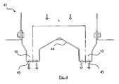
- Each blowing orifice 43 consists of a straight-walled reverse funnel whose lower end is provided with nozzles 10, these nozzles being arranged two by two in the longitudinal direction of the blowing device and are illustrated in detail in FIG. figure 4 .
- the distance in the longitudinal direction between two nozzles is identical to the pitch s between the rollers 8 and the nozzles are also aligned transversely to be positioned exactly above the rollers.
- the blowing orifice has, at the bottom, above the rollers 8, a substantially U-shaped plate 44 in section along the longitudinal axis of the device and provided at the bottom of the U with holes 45 each having a diameter of about 5 mm, to allow the flow of air out of the orifice towards the face of the thin element.
- the distance in the longitudinal direction between the vertical axes of two adjacent holes 45 is about 12 mm.
- the distance between two adjacent holes in the transverse direction is also about 12 mm.
- the two U's are connected by a plate element that is not flat but inverted V-shaped, to help guide the flow of air towards the holes.
- each funnel is offset at the lateral end of the blowing width with respect to the central horizontal axis XX '.
- the jets of fluid projected from the nozzles 10 to the thin element 7 are contained in vertical planes "transverse" that is to say perpendicular to the axis XX 'longitudinal central horizontal.
- the nozzles 10 may have, depending on the width of the enclosure, a greater or lesser overlap area: on the figures 1 and 2 this overlap zone is substantially equal to the entire width of the enclosure 2; this arrangement is chosen to ensure greater homogeneity.
- all the fans 3 are arranged on the same side of the central horizontal axis XX '.
- the enclosure comprises several fans 3, it is also envisaged means for adjusting and separately controlling the temperature and / or the flow rate of the fluid from each of the fans. Any means known per se can be used for this function.
- the subject of the invention is a blowing / heating unit comprising either a device as described above on each of the faces of the thin element; or a device described above which blows on one side, associated with another means of blowing and / or radiative type heating or convective on the other side.
- the present invention thus makes it possible to produce a modular furnace whose different modules (blowing devices) can be aligned so that their central horizontal axes XX 'coincide.
- each blowing device having only one radial flow fan, this blower being the only disposed in a vertical plane comprising the vertical axis of the fan and perpendicular to the central horizontal axis.
Description
La présente invention se rapporte à un four de trempe comportant plusieurs dispositifs de soufflage d'un fluide sur au moins une face d'un élément mince de type vitrage.The present invention relates to a quenching furnace comprising several devices for blowing a fluid on at least one face of a thin glazing element.
Un tel dispositif de soufflage est utilisé dans l'industrie verrière pour réaliser le bombage et/ou la trempe de vitrages.Such a blowing device is used in the glass industry for bending and / or tempering glazing.
Ce dispositif comporte d'une manière habituelle à l'intérieur d'une enceinte ayant un axe horizontal central correspondant à l'axe central de défilement de l'élément mince, un ventilateur à flux radial et à axe vertical ayant une sortie reliée à au moins un conduit alimentant au moins un orifice de soufflage dirigé vers ladite face et réalisant une largeur de soufflage selon un axe transversal horizontal perpendiculaires à l'axe vertical du ventilateur et à l'axe horizontal central de défilement.This device comprises, in a usual way inside an enclosure having a central horizontal axis corresponding to the central axis of travel of the thin element, a radial flow fan with a vertical axis having an output connected to at least one duct supplying at least one blowing orifice directed towards said face and producing a blowing width along a transverse horizontal axis perpendicular to the vertical axis of the blower and to the central horizontal axis of movement.
Il est connu de la demande internationale de brevet N°
Ce document expose que le soufflage doit être symétrique par rapport à l'axe horizontal central de défilement et que pour réaliser ce soufflage symétrique, les moyens de soufflage doivent être disposés de manière symétrique par rapport à l'axe horizontal central de défilement (ou au plan vertical central).This document states that the blowing must be symmetrical with respect to the central horizontal axis of movement and that to achieve this symmetrical blowing, the blowing means must be arranged symmetrically with respect to the central horizontal axis of scrolling (or central vertical plane).
Ce document expose ainsi que deux ventilateurs à flux radial peuvent être disposés en voute de l'enceinte, d'une manière symétrique par rapport au plan vertical central, chaque ventilateur comportant au moins un conduit d'alimentation radial et les deux conduits étant alors disposés symétriquement par rapport au plan vertical central.This document thus states that two radial flow fans may be arranged vaulting the enclosure in a manner symmetrical with respect to the central vertical plane, each fan comprising at least one radial supply duct and the two ducts being then disposed symmetrically with respect to the central vertical plane.
Ce document expose aussi qu'un seul ventilateur à flux radial peut être disposé en voute de l'enceinte, mais que ce ventilateur est alors disposé au centre de la largeur de l'enceinte, ce ventilateur comportant alors au moins deux conduits d'alimentation radiale et ces deux conduits étant alors disposés symétriquement par rapport au plan vertical central.This document also discloses that a single radial flow fan may be disposed in vault of the enclosure, but that this fan is then disposed at the center of the width of the enclosure, this fan then comprising at least two supply ducts. radial and these two ducts then being arranged symmetrically with respect to the central vertical plane.
Cette solution donne techniquement satisfaction car elle permet effectivement de réaliser une répartition homogène du flux d'air à la surface des éléments minces qui défilent à l'intérieur de l'enceinte, mais il est apparu que cela conduisait à une élévation du coût et à une complexification de l'équipement en particulier parce qu'il faut prévoir deux systèmes d'instrumentation différents pour régler les flux gauche et droit (par rapport à l'axe horizontal central de défilement) pour permettre de réaliser la répartition homogène du flux d'air.This solution is technically satisfactory because it effectively makes it possible to achieve a homogeneous distribution of the flow of air on the surface of the thin elements that pass through the enclosure, but it has been found that this leads to an increase in the cost and a complexity of the equipment in particular because it is necessary to provide two different instrumentation systems to adjust the left and right flows (relative to the central horizontal axis of movement) to allow the homogeneous distribution of the flow of air.
Un autre inconvénient du dispositif de soufflage de l'art antérieur réside dans le fait que les moyens de chauffage qui sont disposés dans le conduit sont supportés par des parois latérales de l'enceinte. Il est alors difficile de procéder au retrait de ces moyens, notamment pour les nettoyer ou pour les inspecter.Another disadvantage of the blowing device of the prior art lies in the fact that the heating means which are arranged in the duct are supported by side walls of the enclosure. It is then difficult to withdraw these means, especially for cleaning or inspecting.
L'art antérieur connaît aussi de la demande de brevet
L'art antérieur connaît par ailleurs de la demande de brevet
Le but de l'invention est de pallier les inconvénients de l'art antérieur en proposant un système de soufflage qui permet de réaliser une répartition homogène du flux d'air comme précédemment mais comportant moins de moyens et moins d'instruments et coutant ainsi moins cher.The object of the invention is to overcome the drawbacks of the prior art by proposing a blowing system which makes it possible to achieve a homogeneous distribution of the air flow as before but with fewer means and fewer instruments and thus costing less. expensive.
La présente invention se rapporte ainsi dans son acception la plus large à un four de trempe comportant plusieurs dispositifs de soufflage d'un fluide sur au moins une face d'un élément mince de type vitrage selon la revendication 1. The present invention thus relates in its broadest sense to a tempering furnace comprising a plurality of s device for blowing a fluid on at least one face of a thin element type glazing according to
Ces dispositifs comportent, à l'intérieur d'une enceinte ayant un axe horizontal central correspondant à l'axe central de défilement de l'élément mince, un ventilateur à flux radial et à axe vertical ayant une sortie reliée à au moins un conduit alimentant au moins un orifice de soufflage dirigé vers ladite face et réalisant une largeur de soufflage selon un axe transversal horizontal perpendiculaire à l'axe vertical du ventilateur et perpendiculaire à l'axe horizontal central de défilement.This device s s nt comprises, inside an enclosure having a central horizontal axis corresponding to the central axis of movement of the thin member, a radial flow fan and a vertical axis having an output connected to at least a duct feeding at least one blowing orifice directed towards said face and achieving a blowing width along a horizontal transverse axis perpendicular to the vertical axis of the fan and perpendicular to the central horizontal axis of scrolling.
Ces dispositifs esont remarquables en ce qu'ils comportent un seul ventilateur dans chaque plan vertical comprenant l'axe vertical du ventilateur et perpendiculaire à l'axe horizontal central et en ce que l'axe vertical du ventilateur est disposé à une distance de l'axe horizontal central comprise entre 25 % et 42,5 % de cette largeur de soufflage, c'est-à-dire à une distance comprise entre un quart et un septième de cette largeur de soufflage, en partant de l'axe horizontal central.This device s s es are remarkable in that ls i nt comprises a single fan in each vertical plane containing the vertical axis of the fan and perpendicular to the central horizontal axis and in that the vertical axis of the fan is arranged to a distance from the central horizontal axis of between 25% and 42.5% of this blowing width, that is to say at a distance of between one quarter and one seventh of this blowing width, starting from central horizontal axis.
Le conduit qui relie la sortie du ventilateur à l'orifice de soufflage est orienté, pour l'essentiel, transversalement par rapport à l'axe central de défilement.The duct connecting the fan outlet to the blowing orifice is oriented, essentially, transversely to the central axis of scrolling.
Dans ce dispositif en outre, de préférence, l'axe vertical dudit ventilateur est disposé à une distance de l'axe horizontal central égal à environ un tiers (+ ou - 5 %) de la largeur de soufflage.In this device further, preferably, the vertical axis of said fan is disposed at a distance from the central horizontal axis equal to about one third (+ or - 5%) of the blowing width.
Des moyens de chauffage sont disposés dans ledit conduit et sont, de préférence, supportés par la voute de ladite enceinte, tout comme le ventilateur, afin de faciliter leur entretien : ils peuvent être séparés de l'enceinte et soulevés, par exemple à l'aide d'un treuil ou d'un palan. Par ailleurs, cela permet d'éviter que des connexions ou câbles électriques soient présents sur les faces latérales extérieures du dispositif.Heating means are arranged in said duct and are preferably supported by the vault of said enclosure, as the fan, to facilitate their maintenance: they can be separated from the enclosure and raised, for example to the using a winch or hoist. Moreover, this makes it possible to prevent electrical connections or cables from being present on the outer lateral faces of the device.
Le dispositif selon l'invention comporte par ailleurs au moins un orifice de soufflage comportant, de préférence, une plaque présentant en coupe selon l'axe horizontal central sensiblement une forme de double U, cette plaque présentant une pluralité de trous situés au fond des U. Ces trous sont orientés sensiblement verticalement, c'est-à-dire perpendiculairement à la surface principale de l'élément mince à chauffer.The device according to the invention also comprises at least one blowing orifice preferably comprising a plate having in section along the central horizontal axis substantially a shape of double U, this plate having a plurality of holes located at the bottom of the U These holes are oriented substantially vertically, that is to say perpendicular to the main surface of the thin element to be heated.
Les deux U sont, de préférence, reliés par un élément de plaque en forme de V inversé.The two U's are preferably connected by an inverted V-shaped plate member.
La présente invention se rapporte ainsi à un four de trempe comportant plusieurs dispositifs de soufflage ces dispositifs étant alignés de manière à ce que leurs axes horizontaux centraux coïncident.The present invention thus relates to a quench furnace comprising a plurality of blowing devices, these devices being aligned so that their central horizontal axes coincide.
Tous les ventilateurs des dispositifs de soufflage sont alors disposés du même côté de l'axe horizontal central commun, afin de faciliter la maintenance.All the fans of the blowers are then arranged on the same side of the common central horizontal axis, to facilitate maintenance.
La présente invention ne s'applique pas uniquement aux éléments minces plats, mais aussi aux éléments courbés ou bombés. Elle peut notamment être utilisée pour réaliser la trempe de vitres en verre monolithiques.The present invention does not apply only to thin flat elements, but also to curved or curved elements. It can in particular be used for tempering monolithic glass panes.
La présente invention se rapporte également à un procédé de soufflage selon la revendication 6, mettant en oeuvre en particulier le four de trempe à plusieurs dispositifs selon l'invention, dans lequel le soufflage est opéré sur au moins une face d'un élément mince de type vitrage, l'élément mince défilant à l'intérieur d'une enceinte selon un axe horizontal central, un ventilateur à flux radial et à axe vertical ayant une sortie reliée à au moins un conduit alimentant au moins un orifice de soufflage dirigé vers ladite face et réalisant une largeur de soufflage selon un axe transversal horizontal perpendiculaires à l'axe vertical du ventilateur et à l'axe horizontal central de défilement.The present invention also relates to a blowing method according to claim 6, in particular implementing the multi- device quenching furnace according to the invention, in which blowing is performed on at least one face of a thin element of glazing type, the thin element running inside an enclosure along a central horizontal axis, a radial flow fan with a vertical axis having an outlet connected to at least one duct supplying at least one blowing orifice directed towards said face and realizing a blowing width along a horizontal transverse axis perpendicular to the vertical axis of the fan and the central horizontal axis of scrolling.
Ce procédé de soufflage d'un fluide est remarquable en ce qu'un seul ventilateur dans chaque plan vertical comprenant l'axe vertical du ventilateur et perpendiculaire à l'axe horizontal central souffle et en ce que l'axe vertical dudit ventilateur est disposé à une distance de l'axe horizontal central comprise entre 25 % et 42,5 % de cette largeur de soufflage.This method of blowing a fluid is remarkable in that a single fan in each vertical plane comprising the vertical axis of the fan and perpendicular to the central horizontal axis is blowing and in that the vertical axis of said fan is arranged to a distance from the central horizontal axis of between 25% and 42.5% of this blowing width.
Avantageusement, le dispositif et le procédé selon l'invention permettent ainsi de réaliser une répartition homogène du flux d'air à la surface des éléments minces en utilisant un seul ventilateur et un seul moyen de chauffage.Advantageously, the device and the method according to the invention thus make it possible to achieve a homogeneous distribution of the air flow on the surface of the thin elements by using a single fan and a single heating means.
Avantageusement également, ce moyen de chauffage est disposé en partie supérieure de l'enceinte (en voute) et est ainsi facile d'accès.Advantageously also, this heating means is disposed in the upper part of the enclosure (vault) and is thus easy to access.
Avantageusement également, le coût du dispositif, ainsi que son poids, sont diminués parce que moins de moyens sont nécessaires pour la réalisation du flux d'air chaud (moins de tôle métallique pour réaliser les conduits, moins d'instrumentation pour régler les deux côtés du soufflage).Advantageously also, the cost of the device, as well as its weight, are reduced because less means are needed for the realization of hot air flow (less metal sheet to make the ducts, less instrumentation to adjust the two sides blowing).
Avantageusement enfin, le fonctionnement du dispositif est simplifié et il est même en outre possible de mieux gérer le chauffage et de supprimer l'apparition de points chauds en voute.Advantageously finally, the operation of the device is simplified and it is even moreover possible to better manage the heating and to eliminate the appearance of hotspots vault.
La présente invention sera mieux comprise à la lecture de la description détaillée ci-après d'exemples de réalisation non limitatifs et des figures ci-jointes :
- La
figure 1 illustre une vue en coupe longitudinale partielle dans un plan longitudinal passant par l'axe de rotation d'un ventilateur d'un dispositif de soufflage selon l'invention ; - La
figure 2 illustre une vue en coupe transversale selon AA de lafigure 1 , dans le plan P comprenant l'axe vertical du ventilateur et perpendiculaire à l'axe central horizontal de défilement ; - La
figure 3 illustre une vue de dessus d'un dispositif de soufflage selon l'invention ; et - La
figure 4 illustre une vue en coupe de détail d'un orifice de soufflage.
- The
figure 1 illustrates a partial longitudinal sectional view in a longitudinal plane passing through the axis of rotation of a blower of a blowing device according to the invention; - The
figure 2 illustrates a cross-sectional view along AA of thefigure 1 in the plane P comprising the vertical axis of the fan and perpendicular to the horizontal central axis of scrolling; - The
figure 3 illustrates a top view of a blowing device according to the invention; and - The
figure 4 illustrates a detail sectional view of a blowing orifice.
Il est précisé que dans ces figures les proportions entre les divers éléments représentés ne sont pas rigoureusement respectées et les éléments de coupe dans le plan ou en arrière plan ne sont pas toujours représentés, afin d'en faciliter la lecture.It is specified that in these figures the proportions between the various elements shown are not rigorously respected and the cutting elements in the plane or in the background are not always represented, in order to facilitate reading.
La
L'élément mince 7 a été représenté dans le deuxième dispositif de soufflage pour plus de clarté. Il est entré dans le four par la gauche de la figure et en ressort par la droite.Thin member 7 has been shown in the second blowing device for clarity. He entered the oven from the left of the figure and emerged from the right.
L'élément mince 7 se déplace perpendiculairement au plan de coupe, sur des rouleaux 8 parallèles entre eux, de tout type connu en soi, par exemple d'un diamètre de 10 cm. Ces rouleaux présentent chacun un axe horizontal transversal de rotation, perpendiculaire à l'axe XX' horizontal central, ces axes étant entrainés en rotation par un moyen d'entraînement unique du type chaine ou courroie et ces axes sont séparés les uns des autres d'un pas s de 12 cm par exemple.The thin element 7 moves perpendicular to the cutting plane, on
Chaque dispositif 1 ou unité (ou module) de soufflage comporte à l'intérieur d'une enceinte 2, un seul ventilateur 3. Ce ventilateur est disposé verticalement de tel sorte que l'axe de rotation des éléments produisant le flux d'air soit vertical, selon un axe VV' vertical. Le flux d'air produit par le ventilateur est un flux radial, c'est-à-dire qu'il s'étend, à la sortie du ventilateur, dans une direction horizontale centripète par rapport à l'axe de rotation du ventilateur.Each
Ce flux radial est canalisé à l'aide d'un conduit 51 relié au ventilateur 3 et s'étend sensiblement horizontalement et ce conduit 51 alimente six orifices de soufflage 43 en forme d'entonnoir renversé, tous dirigés vers les rouleaux 8 qui supportent et transportent l'élément mince 7.This radial flow is channeled using a
Entre le ventilateur 3 et les orifices de soufflage 43, sont disposés des moyens de chauffage 6 comportant des résistances électriques en contact avec des ailettes 66 s'étendant verticalement à l'intérieur du conduit 51.Between the
Ces moyens de chauffage 6 sont ainsi supportés par la voute de l'enceinte 2.These heating means 6 are thus supported by the vault of the
L'orifice de soufflage 43 permet ainsi de réaliser un soufflage d'air chaud sur une largeur de soufflage l ici d'environ 2,4 m, visible sur la
L'enceinte 2 de chacun des trois dispositifs de soufflage est parallélépipédique et les trois enceintes 2 sont disposés l'une à la suite de l'autre : l'orifice de sortie par lequel l'élément mince 7 sort du premier dispositif de soufflage correspond ainsi à l'orifice d'entrée par lequel l'élément mince 7 entre dans le second dispositif de soufflage en considérant le sens de défilement de l'élément mince à l'intérieur du four et l'orifice de sortie par lequel l'élément mince 7 sort du second dispositif de soufflage correspond ainsi à l'orifice d'entrée par lequel l'élément mince 7 entre dans le troisième dispositif de soufflage en considérant toujours le sens de défilement de l'élément mince à l'intérieur du four.The
La paroi de l'enceinte 2 comprend quatre plaques constituées de matériau isolant en fibres céramiques.The wall of the
Selon le mode de réalisation de l'invention illustré, la limite inférieure de l'enceinte 2 est constituée par l'ensemble des rouleaux 8 qui supportent et transportent l'élément mince 7. Cet ensemble de rouleaux fait ainsi partie de la sole du four.According to the embodiment of the invention illustrated, the lower limit of the
La hauteur intérieure h de l'enceinte, de l'axe des rouleaux 8 à la face inférieure de la voute est de l'ordre de 1 mètre et l'épaisseur e de la voute est de l'ordre de 30 cm. La hauteur totale de l'enceinte, de l'axe des rouleaux 8 à la face supérieure de la voute est ainsi de l'ordre de 1,3 mètre, ce qui est peu.The inner height h of the enclosure, the axis of the
La longueur totale du four L est de l'ordre de 5 mètres, chaque dispositif de soufflage présentant une longueur L' d'environ 1,8 mètre pour le premier et le troisième dispositif, et une longueur L" d'environ 1,5 mètre pour le second dispositif.The total length of the furnace L is of the order of 5 meters, each blowing device having a length L 'of about 1.8 meters for the first and the third device, and a length L "of about 1.5 meter for the second device.
Chaque dispositif 1 de soufflage comporte un seul ventilateur 3 dans un plan vertical P comprenant l'axe VV' vertical du ventilateur, parallèle à l'axe YY' et perpendiculaire à l'axe XX'.Each
Comme on peut le voir sur les
Cette distance d entre l'axe vertical VV' d'un ventilateur et l'axe XX' horizontal central n'est pas forcément la même pour les trois dispositifs de soufflage, mais elle est toujours comprise entre 25 % et 42,5 % de la largeur de soufflage l.This distance d between the vertical axis VV 'of a fan and the axis XX' central horizontal is not necessarily the same for the three devices of blowing, but it is always between 25% and 42.5% of the blowing width l.
La largeur de soufflage est ici mesurée dans le plan P comprenant l'axe VV'. Elle est juste légèrement inférieure à la largeur intérieure de l'enceinte qui est ici d'environ 2,5 mètres.The blowing width is here measured in the plane P comprising the axis VV '. It is just slightly lower than the inner width of the enclosure which is here about 2.5 meters.
Chaque orifice de soufflage 43 est constitué d'un entonnoir renversé à parois droites dont l'extrémité inférieure est munie de buses 10, ces buses étant disposées deux par deux selon la direction longitudinale du dispositif de soufflage et sont illustrées en détail en
L'orifice de soufflage présente en partie basse, au-dessus des rouleaux 8, une plaque 44 sensiblement en forme de double U en coupe selon l'axe longitudinal du dispositif et pourvue au fond des U de trous 45 présentant chacun un diamètre d'environ 5 mm, afin de permettre au flux d'air de sortir de l'orifice en direction de la face de l'élément mince. La distance selon la direction longitudinale entre les axes verticaux de deux trous 45 adjacents est d'environ 12 mm. La distance entre deux trous adjacents selon la direction transversale est aussi d'environ 12 mm. Comme visible sur la
L'entrée de chaque entonnoir est décalée à l'extrémité latérale de la largeur de soufflage par rapport à l'axe XX' horizontal central.The inlet of each funnel is offset at the lateral end of the blowing width with respect to the central horizontal axis XX '.
Les jets de fluide projetés depuis les buses 10 vers l'élément mince 7 sont contenus dans des plans verticaux « transversaux » c'est-à-dire perpendiculaires à l'axe XX' longitudinal horizontal central.The jets of fluid projected from the
Par ailleurs, les buses 10 peuvent présenter selon la largeur de l'enceinte une zone de recouvrement plus ou moins grande : sur les
Une zone de recouvrement plus petite peut bien entendu être prévue sans sortir du cadre de la présente invention.A smaller overlap area can of course be provided without departing from the scope of the present invention.
Le mouvement général du fluide à l'intérieur de l'enceinte 2 est tel qu'indiqué par les doubles flèches sur les
Ce mouvement, dissymétrique par rapport à l'axe ZZ' vertical central de chaque dispositif de soufflage, permet toutefois de réaliser une répartition à la fois optimale et homogène du fluide sur la surface à traiter.This movement, asymmetrical with respect to the central vertical axis ZZ 'of each blowing device, however makes it possible to achieve an optimal and homogeneous distribution of the fluid on the surface to be treated.
Par ailleurs la disposition des différents constituants, notamment les ventilateurs 3 et les moyens de chauffage 6, assurent un accès fiable facile en cas de réparation et/ou pour l'entretien.Furthermore the arrangement of the various components, including the
Dans le four de trempe illustré, tous les ventilateurs 3 sont disposés du même côté de l'axe XX' horizontal central.In the tempering furnace shown, all the
Lorsque l'enceinte comprend plusieurs ventilateurs 3, il est également envisagé des moyens pour ajuster et contrôler séparément la température et/ou le débit du fluide issu de chacun des ventilateurs. Tout moyen connu en soi peut être utilisé pour cette fonction.When the enclosure comprises
On obtient ainsi des profils de température particuliers et appropriés au niveau du soufflage sur les moyens de transport des éléments minces. Cette modularité est alors très appréciée des utilisateurs.In this way, particular and appropriate temperature profiles are obtained at the blowing point on the means of transport of the thin elements. This modularity is very popular with users.
En outre l'invention a pour objet une unité de soufflage/chauffage comprenant soit un dispositif tel que décrit ci-dessus sur chacune des faces de l'élément mince ; soit un dispositif ci-dessus décrit qui souffle sur une face, associée à un autre moyen de soufflage et/ou de chauffe de type radiatif ou convectif sur l'autre face.In addition, the subject of the invention is a blowing / heating unit comprising either a device as described above on each of the faces of the thin element; or a device described above which blows on one side, associated with another means of blowing and / or radiative type heating or convective on the other side.
Par ailleurs, il est possible de réaliser un four de traitement thermique avec seulement deux dispositifs ou même avec plus de trois dispositifs de soufflage.Furthermore, it is possible to realize a heat treatment furnace with only two devices or even with more than three blowing devices.
La présente invention permet ainsi de réaliser un four modulaire dont les différents modules (dispositifs de soufflage) peuvent être alignés de manière à ce que leurs axes XX' horizontaux centraux coïncident.The present invention thus makes it possible to produce a modular furnace whose different modules (blowing devices) can be aligned so that their central horizontal axes XX 'coincide.
Il pourrait être imaginé de prévoir plusieurs ventilateurs à flux radial à l'intérieur d'un dispositif unique de soufflage, à condition de les positionner le long de l'axe central horizontal de manière à ce qu'un seul ventilateur à flux radial soit disposé dans chaque plan vertical comprenant l'axe vertical du ventilateur et perpendiculaire à l'axe horizontal central.It could be imagined to provide several radial flow fans inside a single blowing device, provided they are positioned along the horizontal central axis so that a single fan to radial flow is disposed in each vertical plane comprising the vertical axis of the fan and perpendicular to the central horizontal axis.
Toutefois, dans le cadre de l'invention, on préfère prévoir plusieurs dispositifs de soufflage alignés de manière à ce que leurs axes XX' horizontaux centraux coïncident, chaque dispositif de soufflage ne comportant qu'un seul ventilateur à flux radial, ce ventilateur étant le seul disposé dans un plan vertical comprenant l'axe vertical du ventilateur et perpendiculaire à l'axe horizontal central. Avec cette solution, les réglages sont facilités par le fait qu'un flux issu d'un ventilateur ne peut venir perturber le flux issu d'un autre ventilateur à l'intérieur d'un dispositif de soufflage.However, in the context of the invention, it is preferred to provide a plurality of blowers aligned so that their central horizontal axes XX 'coincide, each blowing device having only one radial flow fan, this blower being the only disposed in a vertical plane comprising the vertical axis of the fan and perpendicular to the central horizontal axis. With this solution, the settings are facilitated by the fact that a flow from a fan can not disturb the flow from another fan inside a blowing device.
La présente invention est décrite dans ce qui précède à titre d'exemple. Il est entendu que l'homme du métier est à même de réaliser différentes variantes de l'invention sans pour autant sortir du cadre du brevet tel que défini par les revendications.The present invention is described in the foregoing by way of example. It is understood that the skilled person is able to achieve different variants of the invention without departing from the scope of the patent as defined by the claims.
Claims (6)
- A toughening furnace comprising several devices (1) for blowing a fluid onto at least one face of a thin glazing element (7), the devices comprising, inside an enclosure (2) having a central horizontal axis (XX') corresponding to the central axis along which the thin element (7) runs, a radial-flow fan (3) of vertical axis (VV') having an outlet connected to at least one duct (51) feeding at least one blowing orifice (43) directed onto said face and providing a blowing width 1 along a horizontal transverse axis (YY') perpendicular to the axes (XX') and (VV'), the devices being aligned so that their central horizontal axes (XX') coincide, characterized in that each device (1) includes a single fan (3) in each vertical plane P comprising the vertical axis (VV') and perpendicular to the central horizontal axis (XX'), in that all the fans (3) of the devices (1) are placed on the same side of the common central horizontal axis (XX') and in that the vertical axis (VV') of each fan is placed at a distance d from the central horizontal axis (XX') which is between 25% and 42.5% of this blowing width 1.
- The toughening furnace as claimed in claim 1, characterized in that the vertical axis (VV') of said fans (3) is placed at a distance d from the central horizontal axis (XX') equal to around one third of the blowing width 1.
- The toughening furnace as claimed in claim 1 or claim 2, characterized in that heating means (6) are placed in said duct (51) and are supported by the roof of said enclosure (2).
- The toughening furnace as claimed in any one of the preceding claims, characterized in that it comprises at least one blowing orifice (43) comprising a plate (44) having, in cross section along the central horizontal axis (XX'), substantially the form of a double U, this plate having a plurality of holes (45) located on the bottom of the Us.
- The toughening furnace as claimed in the preceding claim, characterized in that the two Us are joined by a plate element in the form of an inverted V.
- A method of blowing a fluid onto at least one face of a thin glazing element (7) employing a toughening furnace comprising several devices (1) for blowing, the thin element (7) running inside an enclosure (2) along a central horizontal axis (XX'), the devices comprising inside the enclosure (2) a radial-flow fan (3) of vertical axis (VV') having an outlet connected to at least one duct (51) feeding at least one blowing orifice (43) directed onto said face and providing a blowing width 1 along a horizontal transverse axis (YY') perpendicular to the axes (XX') and (VV'), the devices being aligned so that their central horizontal axes (XX') coincide, characterized in that a single fan (3) in each vertical plane P comprising the vertical axis (VV') and perpendicular to the central horizontal axis (XX') is blowing, in that all the fans (3) of the devices (1) are placed on the same side of the common central horizontal axis (XX') and in that the vertical axis (VV') of each fan is placed at a distance d from the central horizontal axis (XX') which is between 25% and 42.5% of this blowing width 1.
Priority Applications (2)
| Application Number | Priority Date | Filing Date | Title |
|---|---|---|---|
| PL08837682T PL2200946T3 (en) | 2007-09-18 | 2008-09-18 | Tempering furnace and method comprising several devices for blowing a fluid on the face of a thin member of the glazing type |
| SI200830968T SI2200946T1 (en) | 2007-09-18 | 2008-09-18 | Tempering furnace and method comprising several devices for blowing a fluid on the face of a thin member of the glazing type |
Applications Claiming Priority (2)
| Application Number | Priority Date | Filing Date | Title |
|---|---|---|---|
| FR0757656A FR2921058B1 (en) | 2007-09-18 | 2007-09-18 | DEVICE AND METHOD FOR BLOWING A FLUID ON ONE SIDE OF A GLASS-TYPE THIN MEMBER |
| PCT/FR2008/051671 WO2009047450A1 (en) | 2007-09-18 | 2008-09-18 | Device and method for blowing a fluid on the face of a thin member of the glazing type |
Publications (2)
| Publication Number | Publication Date |
|---|---|
| EP2200946A1 EP2200946A1 (en) | 2010-06-30 |
| EP2200946B1 true EP2200946B1 (en) | 2013-03-06 |
Family
ID=39345200
Family Applications (1)
| Application Number | Title | Priority Date | Filing Date |
|---|---|---|---|
| EP08837682A Active EP2200946B1 (en) | 2007-09-18 | 2008-09-18 | Tempering furnace and method comprising several devices for blowing a fluid on the face of a thin member of the glazing type |
Country Status (6)
| Country | Link |
|---|---|
| EP (1) | EP2200946B1 (en) |
| CN (1) | CN101868427B (en) |
| FR (1) | FR2921058B1 (en) |
| PL (1) | PL2200946T3 (en) |
| SI (1) | SI2200946T1 (en) |
| WO (1) | WO2009047450A1 (en) |
Families Citing this family (2)
| Publication number | Priority date | Publication date | Assignee | Title |
|---|---|---|---|---|
| FI126864B (en) * | 2013-05-23 | 2017-06-30 | Taifin Glass Machinery Oy | Glashärdningsugn |
| EP3487817A1 (en) * | 2016-07-21 | 2019-05-29 | Saint-Gobain Glass France | Nozzle strip for a blowing box for thermally prestressing glass panes |
Family Cites Families (7)
| Publication number | Priority date | Publication date | Assignee | Title |
|---|---|---|---|---|
| DE3536155A1 (en) * | 1985-10-10 | 1987-04-16 | Schmetz Kg | Chamber furnace with gas circulation |
| DE4219003A1 (en) * | 1992-06-10 | 1993-12-16 | Kramer Carl | Gas blowing device for treating glass or ceramic articles - has ventilators maintaining uniform gas speed as it is blown upwards or downwards through perforated conveyor belt |
| DE19538364C5 (en) * | 1995-10-14 | 2007-05-24 | Carl Prof. Dr.-Ing. Kramer | Device for rapid heating of metal press studs |
| FR2821285B1 (en) | 2001-02-23 | 2003-11-28 | Saint Gobain Seva | DEVICE FOR BLOWING A FLUID ON AT LEAST ONE SIDE OF A THIN ELEMENT, AND ASSOCIATED BLOW UNIT |
| JP4400158B2 (en) * | 2003-09-24 | 2010-01-20 | 旭硝子株式会社 | Heating method for plate |
| CN2675662Y (en) * | 2004-01-06 | 2005-02-02 | 信义汽车玻璃(深圳)有限公司 | Air blowing system for glass reinforcing furnace |
| DE102005062584B4 (en) * | 2005-12-27 | 2013-09-26 | Continental Automotive Gmbh | Device and method for debinding ceramic components |
-
2007
- 2007-09-18 FR FR0757656A patent/FR2921058B1/en not_active Expired - Fee Related
-
2008
- 2008-09-18 SI SI200830968T patent/SI2200946T1/en unknown
- 2008-09-18 CN CN2008801163672A patent/CN101868427B/en not_active Expired - Fee Related
- 2008-09-18 EP EP08837682A patent/EP2200946B1/en active Active
- 2008-09-18 WO PCT/FR2008/051671 patent/WO2009047450A1/en active Application Filing
- 2008-09-18 PL PL08837682T patent/PL2200946T3/en unknown
Also Published As
| Publication number | Publication date |
|---|---|
| CN101868427B (en) | 2013-06-26 |
| EP2200946A1 (en) | 2010-06-30 |
| PL2200946T3 (en) | 2013-08-30 |
| FR2921058B1 (en) | 2010-10-15 |
| WO2009047450A1 (en) | 2009-04-16 |
| SI2200946T1 (en) | 2013-07-31 |
| CN101868427A (en) | 2010-10-20 |
| FR2921058A1 (en) | 2009-03-20 |
Similar Documents
| Publication | Publication Date | Title |
|---|---|---|
| EP0106758B1 (en) | Apparatus to assist in the support of a glass sheet brought to its deformation temperature, the sheet being simultaneously supported by mechanical means | |
| EP0169770B1 (en) | Method and apparatus for bending glass sheets into a horizontal position | |
| EP0090790B1 (en) | Apparatus for the heat treatment of articles by convection | |
| EP2513582B1 (en) | Equipment for preheating a continuously moving steel strip | |
| EP0404678B1 (en) | Thermal conditioning furnace | |
| FR2612917A1 (en) | METHOD AND APPARATUS FOR PROFILING GLASS SHEETS, IN PARTICULAR ICE FOR MOTOR VEHICLES | |
| EP2200946B1 (en) | Tempering furnace and method comprising several devices for blowing a fluid on the face of a thin member of the glazing type | |
| EP0939744B1 (en) | Device for cooling convex glass sheets | |
| EP1362012B1 (en) | Device for blowing a fluid on at least a surface of a thin element and associated blowing unit | |
| EP3512343B1 (en) | Cooking module for a linear tunnel oven for bakery products, pastries and the like, and linear tunnel oven comprising at least one such module | |
| EP0928284B1 (en) | Roller-hearth kiln for heating glazing sheets | |
| CA2019487C (en) | Apparatus for contact tempering of glass | |
| FR2802052A1 (en) | IMPROVED DEVICE FOR THE OHMIC HEATING OF A FLUID, INSTALLATION FOR TREATING A FLUID INCORPORATING SUCH A DEVICE AND METHOD FOR TREATING A FLUID BY OHMIC HEATING | |
| EP0044787B1 (en) | Furnace with interchangeable heating walls for the heat treatment of glass sheets | |
| EP1377529B1 (en) | Method and device for heating glass sheets in an oven | |
| CA1283287C (en) | Fluidised bed installation | |
| EP1029933B1 (en) | Device for heat exchanging with a flat product | |
| FR2520346A1 (en) | NOZZLE SYSTEM FOR CONTINUOUSLY PASS SHEET GLASS TEMPERING DEVICE | |
| EP0940372B1 (en) | Apparatus for thermal treatment of glass sheets | |
| EP1000906A1 (en) | Furnace for detecting inclusions of nickelsulfide in glass sheets | |
| EP0512900A1 (en) | Method and apparatus for obtaining wanted temperatures for a glass stream in a feeder channel | |
| FR2464236A1 (en) | GROOVED GAS SOLE BED IN ITS DOWNSTREAM AREA FOR THE HEAT TREATMENT OF GLASS SHEETS | |
| FR3111888A1 (en) | Bending form of glass sheets comprising a heating circuit and a cooling circuit | |
| EP2029951B1 (en) | Method for monitoring lateral burners of a heating furnace | |
| FR2892600A1 (en) | Product e.g. bakery product, baking method for vertical oven, involves blowing hot air flow into baking chamber through inclined blowing nozzles in manner to subject bottom of plate placed immediately above nozzle to hot air flow |
Legal Events
| Date | Code | Title | Description |
|---|---|---|---|
| PUAI | Public reference made under article 153(3) epc to a published international application that has entered the european phase |
Free format text: ORIGINAL CODE: 0009012 |
|
| 17P | Request for examination filed |
Effective date: 20100419 |
|
| AK | Designated contracting states |
Kind code of ref document: A1 Designated state(s): AT BE BG CH CY CZ DE DK EE ES FI FR GB GR HR HU IE IS IT LI LT LU LV MC MT NL NO PL PT RO SE SI SK TR |
|
| AX | Request for extension of the european patent |
Extension state: AL BA MK RS |
|
| DAX | Request for extension of the european patent (deleted) | ||
| 17Q | First examination report despatched |
Effective date: 20110412 |
|
| GRAP | Despatch of communication of intention to grant a patent |
Free format text: ORIGINAL CODE: EPIDOSNIGR1 |
|
| RIC1 | Information provided on ipc code assigned before grant |
Ipc: F27D 7/04 20060101ALI20120822BHEP Ipc: C03B 27/044 20060101ALI20120822BHEP Ipc: C03B 27/04 20060101ALI20120822BHEP Ipc: C03B 25/08 20060101AFI20120822BHEP Ipc: C03B 29/08 20060101ALI20120822BHEP |
|
| GRAS | Grant fee paid |
Free format text: ORIGINAL CODE: EPIDOSNIGR3 |
|
| GRAA | (expected) grant |
Free format text: ORIGINAL CODE: 0009210 |
|
| AK | Designated contracting states |
Kind code of ref document: B1 Designated state(s): AT BE BG CH CY CZ DE DK EE ES FI FR GB GR HR HU IE IS IT LI LT LU LV MC MT NL NO PL PT RO SE SI SK TR |
|
| REG | Reference to a national code |
Ref country code: GB Ref legal event code: FG4D Free format text: NOT ENGLISH |
|
| REG | Reference to a national code |
Ref country code: CH Ref legal event code: EP Ref country code: AT Ref legal event code: REF Ref document number: 599505 Country of ref document: AT Kind code of ref document: T Effective date: 20130315 |
|
| REG | Reference to a national code |
Ref country code: IE Ref legal event code: FG4D Free format text: LANGUAGE OF EP DOCUMENT: FRENCH |
|
| REG | Reference to a national code |
Ref country code: DE Ref legal event code: R096 Ref document number: 602008022778 Country of ref document: DE Effective date: 20130502 |
|
| REG | Reference to a national code |
Ref country code: RO Ref legal event code: EPE |
|
| PG25 | Lapsed in a contracting state [announced via postgrant information from national office to epo] |
Ref country code: ES Free format text: LAPSE BECAUSE OF FAILURE TO SUBMIT A TRANSLATION OF THE DESCRIPTION OR TO PAY THE FEE WITHIN THE PRESCRIBED TIME-LIMIT Effective date: 20130617 Ref country code: NO Free format text: LAPSE BECAUSE OF FAILURE TO SUBMIT A TRANSLATION OF THE DESCRIPTION OR TO PAY THE FEE WITHIN THE PRESCRIBED TIME-LIMIT Effective date: 20130606 Ref country code: SE Free format text: LAPSE BECAUSE OF FAILURE TO SUBMIT A TRANSLATION OF THE DESCRIPTION OR TO PAY THE FEE WITHIN THE PRESCRIBED TIME-LIMIT Effective date: 20130306 |
|
| REG | Reference to a national code |
Ref country code: SK Ref legal event code: T3 Ref document number: E 14061 Country of ref document: SK |
|
| REG | Reference to a national code |
Ref country code: NL Ref legal event code: VDEP Effective date: 20130306 |
|
| PG25 | Lapsed in a contracting state [announced via postgrant information from national office to epo] |
Ref country code: FI Free format text: LAPSE BECAUSE OF FAILURE TO SUBMIT A TRANSLATION OF THE DESCRIPTION OR TO PAY THE FEE WITHIN THE PRESCRIBED TIME-LIMIT Effective date: 20130306 Ref country code: GR Free format text: LAPSE BECAUSE OF FAILURE TO SUBMIT A TRANSLATION OF THE DESCRIPTION OR TO PAY THE FEE WITHIN THE PRESCRIBED TIME-LIMIT Effective date: 20130607 Ref country code: LV Free format text: LAPSE BECAUSE OF FAILURE TO SUBMIT A TRANSLATION OF THE DESCRIPTION OR TO PAY THE FEE WITHIN THE PRESCRIBED TIME-LIMIT Effective date: 20130306 |
|
| REG | Reference to a national code |
Ref country code: PL Ref legal event code: T3 |
|
| PG25 | Lapsed in a contracting state [announced via postgrant information from national office to epo] |
Ref country code: HR Free format text: LAPSE BECAUSE OF FAILURE TO SUBMIT A TRANSLATION OF THE DESCRIPTION OR TO PAY THE FEE WITHIN THE PRESCRIBED TIME-LIMIT Effective date: 20130306 |
|
| PG25 | Lapsed in a contracting state [announced via postgrant information from national office to epo] |
Ref country code: EE Free format text: LAPSE BECAUSE OF FAILURE TO SUBMIT A TRANSLATION OF THE DESCRIPTION OR TO PAY THE FEE WITHIN THE PRESCRIBED TIME-LIMIT Effective date: 20130306 Ref country code: IS Free format text: LAPSE BECAUSE OF FAILURE TO SUBMIT A TRANSLATION OF THE DESCRIPTION OR TO PAY THE FEE WITHIN THE PRESCRIBED TIME-LIMIT Effective date: 20130706 Ref country code: NL Free format text: LAPSE BECAUSE OF FAILURE TO SUBMIT A TRANSLATION OF THE DESCRIPTION OR TO PAY THE FEE WITHIN THE PRESCRIBED TIME-LIMIT Effective date: 20130306 Ref country code: PT Free format text: LAPSE BECAUSE OF FAILURE TO SUBMIT A TRANSLATION OF THE DESCRIPTION OR TO PAY THE FEE WITHIN THE PRESCRIBED TIME-LIMIT Effective date: 20130708 |
|
| PG25 | Lapsed in a contracting state [announced via postgrant information from national office to epo] |
Ref country code: CY Free format text: LAPSE BECAUSE OF FAILURE TO SUBMIT A TRANSLATION OF THE DESCRIPTION OR TO PAY THE FEE WITHIN THE PRESCRIBED TIME-LIMIT Effective date: 20130306 |
|
| REG | Reference to a national code |
Ref country code: HU Ref legal event code: AG4A Ref document number: E017932 Country of ref document: HU |
|
| PLBE | No opposition filed within time limit |
Free format text: ORIGINAL CODE: 0009261 |
|
| STAA | Information on the status of an ep patent application or granted ep patent |
Free format text: STATUS: NO OPPOSITION FILED WITHIN TIME LIMIT |
|
| PG25 | Lapsed in a contracting state [announced via postgrant information from national office to epo] |
Ref country code: DK Free format text: LAPSE BECAUSE OF FAILURE TO SUBMIT A TRANSLATION OF THE DESCRIPTION OR TO PAY THE FEE WITHIN THE PRESCRIBED TIME-LIMIT Effective date: 20130306 |
|
| 26N | No opposition filed |
Effective date: 20131209 |
|
| PG25 | Lapsed in a contracting state [announced via postgrant information from national office to epo] |
Ref country code: IT Free format text: LAPSE BECAUSE OF FAILURE TO SUBMIT A TRANSLATION OF THE DESCRIPTION OR TO PAY THE FEE WITHIN THE PRESCRIBED TIME-LIMIT Effective date: 20130306 |
|
| REG | Reference to a national code |
Ref country code: DE Ref legal event code: R097 Ref document number: 602008022778 Country of ref document: DE Effective date: 20131209 |
|
| BERE | Be: lapsed |
Owner name: SAINT-GOBAIN SEVA Effective date: 20130930 |
|
| PG25 | Lapsed in a contracting state [announced via postgrant information from national office to epo] |
Ref country code: MC Free format text: LAPSE BECAUSE OF FAILURE TO SUBMIT A TRANSLATION OF THE DESCRIPTION OR TO PAY THE FEE WITHIN THE PRESCRIBED TIME-LIMIT Effective date: 20130306 |
|
| REG | Reference to a national code |
Ref country code: CH Ref legal event code: PL |
|
| REG | Reference to a national code |
Ref country code: IE Ref legal event code: MM4A |
|
| PG25 | Lapsed in a contracting state [announced via postgrant information from national office to epo] |
Ref country code: IE Free format text: LAPSE BECAUSE OF NON-PAYMENT OF DUE FEES Effective date: 20130918 Ref country code: CH Free format text: LAPSE BECAUSE OF NON-PAYMENT OF DUE FEES Effective date: 20130930 Ref country code: BE Free format text: LAPSE BECAUSE OF NON-PAYMENT OF DUE FEES Effective date: 20130930 Ref country code: LI Free format text: LAPSE BECAUSE OF NON-PAYMENT OF DUE FEES Effective date: 20130930 |
|
| PG25 | Lapsed in a contracting state [announced via postgrant information from national office to epo] |
Ref country code: MT Free format text: LAPSE BECAUSE OF FAILURE TO SUBMIT A TRANSLATION OF THE DESCRIPTION OR TO PAY THE FEE WITHIN THE PRESCRIBED TIME-LIMIT Effective date: 20130306 |
|
| PG25 | Lapsed in a contracting state [announced via postgrant information from national office to epo] |
Ref country code: LU Free format text: LAPSE BECAUSE OF NON-PAYMENT OF DUE FEES Effective date: 20130918 |
|
| REG | Reference to a national code |
Ref country code: FR Ref legal event code: PLFP Year of fee payment: 9 |
|
| REG | Reference to a national code |
Ref country code: FR Ref legal event code: PLFP Year of fee payment: 10 |
|
| REG | Reference to a national code |
Ref country code: FR Ref legal event code: PLFP Year of fee payment: 11 |
|
| PGFP | Annual fee paid to national office [announced via postgrant information from national office to epo] |
Ref country code: DE Payment date: 20200909 Year of fee payment: 13 Ref country code: LT Payment date: 20200825 Year of fee payment: 13 Ref country code: TR Payment date: 20200911 Year of fee payment: 13 Ref country code: GB Payment date: 20200909 Year of fee payment: 13 Ref country code: SK Payment date: 20200817 Year of fee payment: 13 Ref country code: FR Payment date: 20200930 Year of fee payment: 13 Ref country code: CZ Payment date: 20200909 Year of fee payment: 13 Ref country code: RO Payment date: 20200831 Year of fee payment: 13 |
|
| PGFP | Annual fee paid to national office [announced via postgrant information from national office to epo] |
Ref country code: HU Payment date: 20200817 Year of fee payment: 13 Ref country code: BG Payment date: 20200819 Year of fee payment: 13 Ref country code: PL Payment date: 20200812 Year of fee payment: 13 Ref country code: SI Payment date: 20200819 Year of fee payment: 13 Ref country code: AT Payment date: 20200825 Year of fee payment: 13 |
|
| REG | Reference to a national code |
Ref country code: DE Ref legal event code: R119 Ref document number: 602008022778 Country of ref document: DE |
|
| REG | Reference to a national code |
Ref country code: LT Ref legal event code: MM4D Effective date: 20210918 |
|
| REG | Reference to a national code |
Ref country code: SK Ref legal event code: MM4A Ref document number: E 14061 Country of ref document: SK Effective date: 20210918 |
|
| REG | Reference to a national code |
Ref country code: AT Ref legal event code: MM01 Ref document number: 599505 Country of ref document: AT Kind code of ref document: T Effective date: 20210918 |
|
| GBPC | Gb: european patent ceased through non-payment of renewal fee |
Effective date: 20210918 |
|
| PG25 | Lapsed in a contracting state [announced via postgrant information from national office to epo] |
Ref country code: RO Free format text: LAPSE BECAUSE OF NON-PAYMENT OF DUE FEES Effective date: 20210918 Ref country code: CZ Free format text: LAPSE BECAUSE OF NON-PAYMENT OF DUE FEES Effective date: 20210918 |
|
| REG | Reference to a national code |
Ref country code: SI Ref legal event code: KO00 Effective date: 20220520 |
|
| PG25 | Lapsed in a contracting state [announced via postgrant information from national office to epo] |
Ref country code: SK Free format text: LAPSE BECAUSE OF NON-PAYMENT OF DUE FEES Effective date: 20210918 Ref country code: LT Free format text: LAPSE BECAUSE OF NON-PAYMENT OF DUE FEES Effective date: 20210918 Ref country code: HU Free format text: LAPSE BECAUSE OF NON-PAYMENT OF DUE FEES Effective date: 20210919 Ref country code: GB Free format text: LAPSE BECAUSE OF NON-PAYMENT OF DUE FEES Effective date: 20210918 Ref country code: FR Free format text: LAPSE BECAUSE OF NON-PAYMENT OF DUE FEES Effective date: 20210930 Ref country code: DE Free format text: LAPSE BECAUSE OF NON-PAYMENT OF DUE FEES Effective date: 20220401 Ref country code: BG Free format text: LAPSE BECAUSE OF NON-PAYMENT OF DUE FEES Effective date: 20220331 |
|
| PG25 | Lapsed in a contracting state [announced via postgrant information from national office to epo] |
Ref country code: AT Free format text: LAPSE BECAUSE OF NON-PAYMENT OF DUE FEES Effective date: 20210918 |
|
| PG25 | Lapsed in a contracting state [announced via postgrant information from national office to epo] |
Ref country code: PL Free format text: LAPSE BECAUSE OF NON-PAYMENT OF DUE FEES Effective date: 20210918 |