EP0090785B1 - Anordnung zur Steuerung der Strom- und/oder Spannungswerte die an den Elektrodengruppen einer Anlage anliegen, die verschiedene elektrostatische Staubabscheider umfasst - Google Patents
Anordnung zur Steuerung der Strom- und/oder Spannungswerte die an den Elektrodengruppen einer Anlage anliegen, die verschiedene elektrostatische Staubabscheider umfasst Download PDFInfo
- Publication number
- EP0090785B1 EP0090785B1 EP83850079A EP83850079A EP0090785B1 EP 0090785 B1 EP0090785 B1 EP 0090785B1 EP 83850079 A EP83850079 A EP 83850079A EP 83850079 A EP83850079 A EP 83850079A EP 0090785 B1 EP0090785 B1 EP 0090785B1
- Authority
- EP
- European Patent Office
- Prior art keywords
- change
- separator
- dust
- separators
- energy
- Prior art date
- Legal status (The legal status is an assumption and is not a legal conclusion. Google has not performed a legal analysis and makes no representation as to the accuracy of the status listed.)
- Expired
Links
- 239000000428 dust Substances 0.000 title claims abstract description 109
- 238000009434 installation Methods 0.000 title claims abstract description 39
- 230000008859 change Effects 0.000 claims abstract description 60
- 230000000694 effects Effects 0.000 claims description 17
- 238000000034 method Methods 0.000 claims description 13
- 238000000926 separation method Methods 0.000 claims description 10
- 230000003466 anti-cipated effect Effects 0.000 claims description 3
- 238000011156 evaluation Methods 0.000 abstract description 8
- 239000007789 gas Substances 0.000 abstract description 5
- 230000004075 alteration Effects 0.000 abstract description 4
- 239000004020 conductor Substances 0.000 description 8
- 239000002245 particle Substances 0.000 description 7
- 230000009467 reduction Effects 0.000 description 7
- 230000006870 function Effects 0.000 description 5
- 230000008901 benefit Effects 0.000 description 4
- 238000010586 diagram Methods 0.000 description 4
- 230000015654 memory Effects 0.000 description 4
- UGFAIRIUMAVXCW-UHFFFAOYSA-N Carbon monoxide Chemical compound [O+]#[C-] UGFAIRIUMAVXCW-UHFFFAOYSA-N 0.000 description 3
- 239000011248 coating agent Substances 0.000 description 3
- 238000000576 coating method Methods 0.000 description 3
- 239000003546 flue gas Substances 0.000 description 3
- 238000004804 winding Methods 0.000 description 3
- 125000004122 cyclic group Chemical group 0.000 description 2
- 230000005684 electric field Effects 0.000 description 2
- 238000005265 energy consumption Methods 0.000 description 2
- 238000012956 testing procedure Methods 0.000 description 2
- 239000008186 active pharmaceutical agent Substances 0.000 description 1
- 230000015556 catabolic process Effects 0.000 description 1
- 230000001419 dependent effect Effects 0.000 description 1
- 230000002349 favourable effect Effects 0.000 description 1
- 238000012986 modification Methods 0.000 description 1
- 230000004048 modification Effects 0.000 description 1
- 238000012552 review Methods 0.000 description 1
Images
Classifications
-
- B—PERFORMING OPERATIONS; TRANSPORTING
- B03—SEPARATION OF SOLID MATERIALS USING LIQUIDS OR USING PNEUMATIC TABLES OR JIGS; MAGNETIC OR ELECTROSTATIC SEPARATION OF SOLID MATERIALS FROM SOLID MATERIALS OR FLUIDS; SEPARATION BY HIGH-VOLTAGE ELECTRIC FIELDS
- B03C—MAGNETIC OR ELECTROSTATIC SEPARATION OF SOLID MATERIALS FROM SOLID MATERIALS OR FLUIDS; SEPARATION BY HIGH-VOLTAGE ELECTRIC FIELDS
- B03C3/00—Separating dispersed particles from gases or vapour, e.g. air, by electrostatic effect
- B03C3/34—Constructional details or accessories or operation thereof
- B03C3/66—Applications of electricity supply techniques
- B03C3/68—Control systems therefor
-
- Y—GENERAL TAGGING OF NEW TECHNOLOGICAL DEVELOPMENTS; GENERAL TAGGING OF CROSS-SECTIONAL TECHNOLOGIES SPANNING OVER SEVERAL SECTIONS OF THE IPC; TECHNICAL SUBJECTS COVERED BY FORMER USPC CROSS-REFERENCE ART COLLECTIONS [XRACs] AND DIGESTS
- Y10—TECHNICAL SUBJECTS COVERED BY FORMER USPC
- Y10S—TECHNICAL SUBJECTS COVERED BY FORMER USPC CROSS-REFERENCE ART COLLECTIONS [XRACs] AND DIGESTS
- Y10S323/00—Electricity: power supply or regulation systems
- Y10S323/903—Precipitators
Definitions
- the present invention refers to a method and an arrangement for permitting control of the current and/or voltage values connected to the respective electrode groups in an installation comprising several electrostatic dust separators or electrode groups so that the total current and voltage requirement of the installation can be minimised to give a desired dust loss.
- electrostatic dust separator installation comprising several electrostatic dust separators does not only mean an installation divided into a plurality of electrode groups, where the current and/or voltage values are controlled in each electrode groups but also mean an installation comprising a number of electrostatic dust separators, where the current and/or voltage values are controlled by a control arrangement for each separator.
- the installation indicates for this purpose a unit, which evaluates an actual dust loss, and a control arrangement appertaining to each electrode groups, so arranged that as a function of control signals received it raises or lowers the current and/or voltage values for the associated electrode group.
- Electrostatic dust separators are already known and a large number of different designs have been referred to.
- Electrostatic dust separators are based on the fundamental principle that the higher the voltage and/or current which is present between the electrodes forming part of the dust separator, the better and the more effective the dust separation. However the voltage and/or the current cannot be excessively high, because flashover will then occur between the electrodes.
- control arrangement feeds its electrode group at the maximum voltage and/or current to which the electrode group concerned can be subjected without an unacceptable number of flashovers or breakdowns occurring per unit time.
- the arrangement referred to here is based on the principle that the power input to the electrostatic filter will, via a signal which is proportional to the power input, be supplied to a controller circuit so as to minimise the energy consumption. Simultaneously signals corresponding to the energy quantities supplied are fed into the said controller circuit for the remaining electrostatic dust separators which form part of the installation. By this means the sum of the energy inputs is formed and the controller circuit is adapted so as to be able to minimise the energy sums.
- the fundamental principle here is that the energy input to the individual electrostatic dust separator is calculated in an iterative manner.
- the fundamental idea in the previously known arrangements is to employ the measured outgoing dust concentration in the cleaned gases (dust loss) for controlling the energy supply to the filter.
- dust loss the measured outgoing dust concentration in the cleaned gases
- the present invention relates to an arrangement, as stated in the preamble of claim 1 and 6.
- the main advantages which can be regarded as being linked with a method and an arrangement in accordance with the present invention are that it has become possible to check the electrode groups forming part of the installation, on the one hand as regards their function, but mainly concerning the contribution made by the electrode group in changing the dust loss on the part of the entire installation as a function of a certain change in the current and/or voltage value, which in turn gives the advantage that only that electrode group, or those electrode groups, which give the maximum change in dust loss in the event of the said change in current and/or voltage values can be permitted to operate with the changed current and/or voltage value.
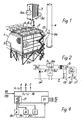
- Fig. 1 thus provides a perspective view of an example of an electrostatic dust separator installation 1 consisting of a plurality of parallel flue gas chambers each having four electrode groups.
- One transformer/rectifier unit is required for each of these electrode groups, but in Fig. 1 only the unit which is provided for electrode group 1 has been illustrated and this has been given the notation number 3.
- the location of the electrode groups is fundamentally such that the outlet of one group is connected directly to the inlet of the subsequent group, etc.
- group 2 . is the last group, its outlet is connected with a chimney stack 4.
- the dust separator installation 1 is of the type where air carrying particles is connected to an inlet 5 and is allowed to pass into the first electrode group.
- the particles are electrically charged by the electrical field which forms between plate electrides which are located adjacent to each other with emission electrodes placed between them, by virtue of the fact that a high direct voltage is connected to the emission electrodes.
- a particle of dust which enters this field becomes electrically negatively charged and this particle will then be attracted by the positive plate electrode and repelled by the negative electrode, and consequently particles accumulate at the plates.
- the air which is cleaned by the electrode groups in turn then passes out through the outlet 5a to the stack 4.
- Fig. 2 illustrates a simplified connection diagram for a transormer/rectifier unit which shows that the alternating current conductor 6a is connected to two thyristors 8, 8a connected in opposition, each provided with its own control electrode 8', 8a', which are connected to a control arrangement indicated in Fig. 2 but not described in detail.
- control arrangement as such is of a type already known and can consist of a control arrangement such as is described in detail in Swedish patent application 81 04574-2.
- This provides control of the current by means of an inductance forming part of a transformer winding »T1».
- the transformer winding »T1» interacts with transformer winding »T2» which is connected to a rectifier bridge 9.
- the negative voltage which can be regarded as having been rectified and smoothed because of the capacitance which is present between the earthed plate electrode 11 and the emission electrode 10, is connected to the emission electrode 10 in the dust separator 2.
- control arrangement 7 For control of the electrode group or the dust separator the control arrangement 7 requires information concerning the instantaneously-prevailing direct voltage and direct current values and these can be evaluated via a conductor 1-2 whilst the instantaneous direct current values can be evaluated via a conductor 13. The passages through zero of the alternating voltage can be evaluated via conductor 14.
- the main task of the control arrangement 7 is to control the signals on conductors 8' and 8a' in time, by this means permitting regulation of the current and/or voltage values prevailing in electrode group 2.
- a circuit as shown in Fig. 2 is thus connected to each of the different electrode groups which form part of the installation.
- the operating sequence of an arrangement must, in an installation 1 consisting of several electrode groups A, B, C, permit regulation of the current and/or voltage values connected to the respective groups, so that the total current and voltage requirement for the installation can be minimised for a required loss of dust.
- a unit 15 which evaluates the instantaneously prevailing dust concentration or dust losses, located in the outgoing cleaned gases in the outlet 5a.
- the present invention is based on . the fact that any of the units whatever can be employed, but with the aim of achieving simplification, only one unit which assesses the dust losses has been illustrated.
- a control arrangement in accordance with Fig. 2, which is assigned to each electrode group A, B, C is required and this is arranged so that, dependent on the control signals received, it raises or lowers the current and/or voltage values for the assigned electrode group.
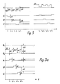
- Fig. 3 illustrates, by notation letters A, B, C, the three electrode groups and the change in the current and/or voltage brought about by an actuating device.
- the letter »S denotes a permissible loss of dust or a maximum permissible dust concentration in the outgoing cleaned gases
- the letters »SR indicate the actual instantaneous dust loss
- the letters »dS illustrate a change in the actual dust loss.
- the letters »dE denote a change in the current and/or voltage value for the dust separator and actually illustrate an energy ramp.
- An actuating device 16 which is common to all the electrode groups A, B, C and which will be described in more detail later with reference to Fig. 4 is so arranged that during a first period of time between time periods »t 1 » and »t 2 » it instantaneously changes the actual current and/or voltage value for an initial group A and, after evaluation of a change in the dust loss »DS» of the installation which corresponds to the change, it stores the said change. During the second period of time, between times »t 2 » and »t 3 » the changed current and/or voltage value is restored to the actual value prevailing prior to the alteration for electrode group A.
- the actuating device 16 is arranged to instantaneously alter the actual current and/or voltage value for a second group B and, after evaluation of the change in the dust loss »dS» of the installation which corresponds to the alteration, to store the said change, preferably in the actuating device 16.
- Fig. 3 shows that »dS» for the change which is allocated to the group B comprises the lowest value, whilst the change assigned to group C represents the highest value.
- the example now shown illustrates how the actual dust loss »SR» is located below the permissible loss limit »S» and there is then a reduction in voltage or current for groups A, B, and C.
- the actuating device is arranged to increase the current and/or voltage value for group A and during the time period »t " » and »t i2 » a reduction occurs in the dust losses towards the permissible value »S».
- the increase in current and/or voltage for group B gives rise to a smaller change in the dust loss »SR», the same also applying during the period of time »t 15 » and »tie» when group C is subjected to an increase current and/or voltage value.
- Fig. 4 shows in highly simplified form an actuating device 16 which can well include a computer device for controlling the testing procedure, preferably a cyclic testing procedure.
- a conductor »SR to the actuating device 16 which is designed to provide information regarding the actual loss of dust received from the unit 15 which evaluates the loss of dust.
- Via conductor »A» a control signal is sent to the control arrangement for group A, which is then arranged, during the time period »ti» and »t 2 » to bring about a reduction in current and/or voltage.
- the change in dust loss divided by the change in current and/or voltage reduction, or energy reduction, is evaluated in a unit 17 and is then stored in a memory 18.
- time period »t 3 » and »t 4 » the corresponding information for group B is stored in a memory 19.
- the value obtained during the period of time »t 5 » and »t 6 » for group C is stored in unit 20.
- the calculation unit 21 that the dust separator or separators which in combination provide a change in the actual dust loss to the desired dust loss in the event of applied change in current and/or voltage are supplied with this value via the actuating device.
- the actuating device 16 can of course also be arranged to check, via the calculation circuit 21, that all groups give a minimum anticipated change in the dust loss in the event of a certain change in the current and/or voltage value. Even though the actuating device 16 is not shown in detail, this with a view to obtaining simplification, it can be mentioned that the actuating device 16 should with advantage be capable of controlling the loss of dust in the chimney stack 4 in accordance with the following procedure.
- the actuating device 16 is to regulate the loss of dust in the stack 4 to the value 50 (mg/N m 3 ).
- the actuating device 16 is arranged to increase the power input to one group at a time by 1 kW in order to check what sort of result this increase will give as regards the change in dust losses.
- the actuating device 16 can be permitted to increase either:
- the actuating device 16 must be capable of evaluating and producing control signals in order to increase the sixth group by 1,25 kW.
- the actuating device 16 should specify that the sixth group is increased by 1 kW whilst the fifth group is increased by 0,25 kW, or that the sixth and fifth group are each increased by 0,63 kW.
- the actuating device 16 should reduce the first group by 5 kW or, if this group gives only 3 kW, reduce this group by 3 kW (shut down) and reduce the other group by 2 kW.
- Fig. 3a shows how the dust loss SR varies with the value dS as a function of an increase in energy dE of similar magnitude in groups A, B and C.
Landscapes
- Engineering & Computer Science (AREA)
- Automation & Control Theory (AREA)
- Electrostatic Separation (AREA)
- Electrostatic Spraying Apparatus (AREA)
- Sampling And Sample Adjustment (AREA)
- Emergency Protection Circuit Devices (AREA)
- Packaging Of Special Articles (AREA)
- Control Of Eletrric Generators (AREA)
Claims (10)
Priority Applications (1)
| Application Number | Priority Date | Filing Date | Title |
|---|---|---|---|
| AT83850079T ATE29223T1 (de) | 1982-03-25 | 1983-03-23 | Anordnung zur steuerung der strom- und/oder spannungswerte die an den elektrodengruppen einer anlage anliegen, die verschiedene elektrostatische staubabscheider umfasst. |
Applications Claiming Priority (2)
| Application Number | Priority Date | Filing Date | Title |
|---|---|---|---|
| SE8201907A SE430472B (sv) | 1982-03-25 | 1982-03-25 | Anordning for att i en elektrofilteranleggning med ett flertal elektrodgrupper mojliggora en reglering av strom- och/eller spenningsverdena anslutna till resp elektrodgrupp sa att totala energibehovet kan minimeras mot. |
| SE8201907 | 1982-03-25 |
Publications (2)
| Publication Number | Publication Date |
|---|---|
| EP0090785A1 EP0090785A1 (de) | 1983-10-05 |
| EP0090785B1 true EP0090785B1 (de) | 1987-09-02 |
Family
ID=20346359
Family Applications (1)
| Application Number | Title | Priority Date | Filing Date |
|---|---|---|---|
| EP83850079A Expired EP0090785B1 (de) | 1982-03-25 | 1983-03-23 | Anordnung zur Steuerung der Strom- und/oder Spannungswerte die an den Elektrodengruppen einer Anlage anliegen, die verschiedene elektrostatische Staubabscheider umfasst |
Country Status (11)
| Country | Link |
|---|---|
| US (1) | US4490159A (de) |
| EP (1) | EP0090785B1 (de) |
| JP (1) | JPS58214362A (de) |
| AT (1) | ATE29223T1 (de) |
| AU (1) | AU556371B2 (de) |
| CA (1) | CA1201472A (de) |
| DE (1) | DE3373278D1 (de) |
| DK (1) | DK168275B1 (de) |
| NZ (1) | NZ203675A (de) |
| SE (1) | SE430472B (de) |
| ZA (1) | ZA831853B (de) |
Families Citing this family (19)
| Publication number | Priority date | Publication date | Assignee | Title |
|---|---|---|---|---|
| DE3326041A1 (de) * | 1983-07-20 | 1985-02-07 | Siemens AG, 1000 Berlin und 8000 München | Regeleinrichtung fuer ein elektrofilter |
| SE451675B (sv) * | 1983-10-05 | 1987-10-26 | Flaekt Ab | Sett och anordning for att variera en mellan elektrostatiska stoftavskiljares elektroder upptredande spenning |
| GB2149594A (en) * | 1983-11-09 | 1985-06-12 | Smidth & Co As F L | Fast-acting spark-over detector |
| AU579846B2 (en) * | 1984-01-11 | 1988-12-15 | Mobil Oil Corporation | Process for isomerizing alkyl aromatic hydrocarbons |
| SE458988B (sv) * | 1986-11-28 | 1989-05-29 | Flaekt Ab | Saett att i en elektrostatisk stoftavskiljare faststaella en aendring i stoftavskiljningen |
| US4987839A (en) * | 1990-05-14 | 1991-01-29 | Wahlco, Inc. | Removal of particulate matter from combustion gas streams |
| US5597403A (en) * | 1994-06-07 | 1997-01-28 | The Chemithon Corporation | Flue gas conditioning system for intermittently energized precipitation |
| RU2200343C2 (ru) * | 2000-10-05 | 2003-03-10 | Общество с ограниченной ответственностью "ПИК" | Устройство управления процессом очистки газа в электрофильтре |
| RU2173218C1 (ru) * | 2000-10-05 | 2001-09-10 | Общество с ограниченной ответственностью "ПИК" | Способ управления процессом очистки газов в электрофильтре |
| US7261765B2 (en) * | 2004-12-29 | 2007-08-28 | Anzai, Setsu | Electrostatic precipitator |
| US20060278074A1 (en) * | 2005-06-09 | 2006-12-14 | Tseng Dan Y | Electrostatic air purifier with a laterally removable collection grid module |
| KR101544512B1 (ko) * | 2014-05-31 | 2015-08-13 | 주식회사 엔아이티코리아 | 고전압 트랜스포머의 pcb 제어 방식의 집진 장치 |
| US20170354980A1 (en) | 2016-06-14 | 2017-12-14 | Pacific Air Filtration Holdings, LLC | Collecting electrode |
| US10882053B2 (en) | 2016-06-14 | 2021-01-05 | Agentis Air Llc | Electrostatic air filter |
| US10828646B2 (en) | 2016-07-18 | 2020-11-10 | Agentis Air Llc | Electrostatic air filter |
| CH713394A1 (de) * | 2017-01-30 | 2018-07-31 | Clean Air Entpr Ag | Elektrofilter. |
| US10792673B2 (en) | 2018-12-13 | 2020-10-06 | Agentis Air Llc | Electrostatic air cleaner |
| US10875034B2 (en) | 2018-12-13 | 2020-12-29 | Agentis Air Llc | Electrostatic precipitator |
| US20200188931A1 (en) * | 2018-12-13 | 2020-06-18 | Pacific Air Filtration Holdings, LLC | Electronic device with advanced control features |
Family Cites Families (9)
| Publication number | Priority date | Publication date | Assignee | Title |
|---|---|---|---|---|
| US2724086A (en) * | 1951-05-11 | 1955-11-15 | Svenska Flaklfabriken Ab | Current regulating system |
| US2978065A (en) * | 1957-07-03 | 1961-04-04 | Svenska Flaektfabriken Ab | Regulating electric precipitators |
| DE1457091B2 (de) * | 1964-09-18 | 1971-10-07 | Metallgesellschaft AG, 6000 Frank fürt | Vorrichtung zur erhoehung des abscheidegrades von elektro statischen staubabscheidern |
| SU364347A1 (ru) * | 1971-04-28 | 1972-12-28 | Способ автоматического регулирования напряжения многопольных электрофильтров | |
| DE2949786A1 (de) * | 1979-12-11 | 1981-06-19 | Siemens AG, 1000 Berlin und 8000 München | Verfahren zum ermitteln der filterstromgrenze eines elektrofilters |
| DE2949797A1 (de) * | 1979-12-11 | 1981-06-19 | Siemens AG, 1000 Berlin und 8000 München | Verfahren zum optimieren einer elektrofilteranlage |
| JPS56500808A (de) * | 1980-03-17 | 1981-06-18 | ||
| DE3027172A1 (de) * | 1980-07-17 | 1982-02-18 | Siemens AG, 1000 Berlin und 8000 München | Verfahren zum betrieb eines elektrofilters |
| SE8104574L (sv) * | 1981-07-28 | 1983-01-29 | Svenska Flaektfabriken Ab | Styranordning for en elektrostatisk stoftavskiljare |
-
1982
- 1982-03-25 SE SE8201907A patent/SE430472B/sv not_active IP Right Cessation
-
1983
- 1983-03-16 ZA ZA831853A patent/ZA831853B/xx unknown
- 1983-03-17 AU AU12537/83A patent/AU556371B2/en not_active Withdrawn - After Issue
- 1983-03-17 US US06/476,217 patent/US4490159A/en not_active Expired - Fee Related
- 1983-03-23 AT AT83850079T patent/ATE29223T1/de not_active IP Right Cessation
- 1983-03-23 DE DE8383850079T patent/DE3373278D1/de not_active Expired
- 1983-03-23 EP EP83850079A patent/EP0090785B1/de not_active Expired
- 1983-03-24 DK DK134883A patent/DK168275B1/da active
- 1983-03-24 NZ NZ203675A patent/NZ203675A/en unknown
- 1983-03-24 CA CA000424429A patent/CA1201472A/en not_active Expired
- 1983-03-25 JP JP58049062A patent/JPS58214362A/ja active Pending
Also Published As
| Publication number | Publication date |
|---|---|
| JPS58214362A (ja) | 1983-12-13 |
| DK134883D0 (da) | 1983-03-24 |
| AU1253783A (en) | 1983-09-29 |
| NZ203675A (en) | 1985-11-08 |
| DE3373278D1 (en) | 1987-10-08 |
| SE430472B (sv) | 1983-11-21 |
| ATE29223T1 (de) | 1987-09-15 |
| EP0090785A1 (de) | 1983-10-05 |
| ZA831853B (en) | 1984-03-28 |
| AU556371B2 (en) | 1986-10-30 |
| CA1201472A (en) | 1986-03-04 |
| DK168275B1 (da) | 1994-03-07 |
| SE8201907L (sv) | 1983-09-26 |
| DK134883A (da) | 1983-09-26 |
| US4490159A (en) | 1984-12-25 |
Similar Documents
| Publication | Publication Date | Title |
|---|---|---|
| EP0090785B1 (de) | Anordnung zur Steuerung der Strom- und/oder Spannungswerte die an den Elektrodengruppen einer Anlage anliegen, die verschiedene elektrostatische Staubabscheider umfasst | |
| AU631627B2 (en) | Method for controlling the current pulse supply to an electrostatic precipitator | |
| US5059219A (en) | Electroprecipitator with alternating charging and short collector sections | |
| CA2159709C (en) | System for controlling an electrostatic precipitator using digital signal processing | |
| DE102008010274B4 (de) | Elektrostatischer Abscheider mit einem funkenstrombegrenzenden Widerstand und Verfahren zum Begrenzen einer Funkenbildung | |
| US4216000A (en) | Resistive anode for corona discharge devices | |
| CA1190277A (en) | Control device for an electrostatic dust separator | |
| US5173867A (en) | Multiple rapper control for electrostatic precipitator | |
| RU2747395C2 (ru) | Электрофильтр | |
| EP0140855B1 (de) | Verfahren und Einrichtung zum Verändern der an die Elektrode eines elektrostatischen Staubabscheiders angebrachten Spannung | |
| EP0030321B1 (de) | Verfahren und Vorrichtung zum Optimieren einer Elektrofilteranlage | |
| US2764254A (en) | Electrostatic precipitator circuits | |
| US3049848A (en) | Electrostatic precipitator circuits | |
| US2395927A (en) | Electrical precipitator | |
| AU8338087A (en) | A method and an arrangement for enabling changes in the level of dust extraction in dust precipitators to be determined | |
| CA1114891A (en) | Pulsed electrostatic precipitator | |
| SU1083312A1 (ru) | Устройство дл электростатического осаждени высокоомных пылей | |
| Frisch et al. | Backfitting electrostatic precipitators: gas velocity and reliability considerations | |
| JPS5855059A (ja) | 電気集塵方法およびその装置 | |
| WO1991006372A1 (en) | Multiple rapper control for electrostatic precipitator | |
| GB2072051A (en) | Resistive passive electrode for corona discharge devices |
Legal Events
| Date | Code | Title | Description |
|---|---|---|---|
| PUAI | Public reference made under article 153(3) epc to a published international application that has entered the european phase |
Free format text: ORIGINAL CODE: 0009012 |
|
| AK | Designated contracting states |
Kind code of ref document: A1 Designated state(s): AT BE CH DE FR GB IT LI NL SE Designated state(s): AT BE CH DE FR GB IT LI NL SE |
|
| 17P | Request for examination filed |
Effective date: 19831209 |
|
| GRAA | (expected) grant |
Free format text: ORIGINAL CODE: 0009210 |
|
| AK | Designated contracting states |
Kind code of ref document: B1 Designated state(s): AT BE CH DE FR GB IT LI NL SE |
|
| PG25 | Lapsed in a contracting state [announced via postgrant information from national office to epo] |
Ref country code: NL Effective date: 19870902 Ref country code: IT Free format text: LAPSE BECAUSE OF FAILURE TO SUBMIT A TRANSLATION OF THE DESCRIPTION OR TO PAY THE FEE WITHIN THE PRESCRIBED TIME-LIMIT;WARNING: LAPSES OF ITALIAN PATENTS WITH EFFECTIVE DATE BEFORE 2007 MAY HAVE OCCURRED AT ANY TIME BEFORE 2007. THE CORRECT EFFECTIVE DATE MAY BE DIFFERENT FROM THE ONE RECORDED. Effective date: 19870902 Ref country code: FR Free format text: LAPSE BECAUSE OF NON-PAYMENT OF DUE FEES Effective date: 19870902 Ref country code: BE Effective date: 19870902 Ref country code: AT Effective date: 19870902 |
|
| REF | Corresponds to: |
Ref document number: 29223 Country of ref document: AT Date of ref document: 19870915 Kind code of ref document: T |
|
| PG25 | Lapsed in a contracting state [announced via postgrant information from national office to epo] |
Ref country code: SE Effective date: 19870930 |
|
| REF | Corresponds to: |
Ref document number: 3373278 Country of ref document: DE Date of ref document: 19871008 |
|
| REG | Reference to a national code |
Ref country code: CH Ref legal event code: PL |
|
| EN | Fr: translation not filed | ||
| NLV1 | Nl: lapsed or annulled due to failure to fulfill the requirements of art. 29p and 29m of the patents act | ||
| PLBI | Opposition filed |
Free format text: ORIGINAL CODE: 0009260 |
|
| 26 | Opposition filed |
Opponent name: SIEMENS AKTIENGESELLSCHAFT, BERLIN UND MUENCHEN Effective date: 19880531 Opponent name: METALLGESELLSCHAFT AG, FRANKFURT/M Effective date: 19880601 |
|
| PG25 | Lapsed in a contracting state [announced via postgrant information from national office to epo] |
Ref country code: DE Effective date: 19881201 |
|
| PG25 | Lapsed in a contracting state [announced via postgrant information from national office to epo] |
Ref country code: GB Effective date: 19890323 |
|
| RDAG | Patent revoked |
Free format text: ORIGINAL CODE: 0009271 |
|
| STAA | Information on the status of an ep patent application or granted ep patent |
Free format text: STATUS: PATENT REVOKED |
|
| GBPC | Gb: european patent ceased through non-payment of renewal fee | ||
| REG | Reference to a national code |
Ref country code: CH Ref legal event code: PL |
|
| 27W | Patent revoked |
Effective date: 19890729 |
|
| GBPR | Gb: patent revoked under art. 102 of the ep convention designating the uk as contracting state |