EP0090518B1 - Thermally insulating blocks - Google Patents
Thermally insulating blocks Download PDFInfo
- Publication number
- EP0090518B1 EP0090518B1 EP83301228A EP83301228A EP0090518B1 EP 0090518 B1 EP0090518 B1 EP 0090518B1 EP 83301228 A EP83301228 A EP 83301228A EP 83301228 A EP83301228 A EP 83301228A EP 0090518 B1 EP0090518 B1 EP 0090518B1
- Authority
- EP
- European Patent Office
- Prior art keywords
- strips
- block
- retaining means
- thermally insulating
- under compression
- Prior art date
- Legal status (The legal status is an assumption and is not a legal conclusion. Google has not performed a legal analysis and makes no representation as to the accuracy of the status listed.)
- Expired
Links
Images
Classifications
-
- F—MECHANICAL ENGINEERING; LIGHTING; HEATING; WEAPONS; BLASTING
- F27—FURNACES; KILNS; OVENS; RETORTS
- F27D—DETAILS OR ACCESSORIES OF FURNACES, KILNS, OVENS, OR RETORTS, IN SO FAR AS THEY ARE OF KINDS OCCURRING IN MORE THAN ONE KIND OF FURNACE
- F27D1/00—Casings; Linings; Walls; Roofs
- F27D1/0003—Linings or walls
- F27D1/0006—Linings or walls formed from bricks or layers with a particular composition or specific characteristics
- F27D1/0009—Comprising ceramic fibre elements
- F27D1/0013—Comprising ceramic fibre elements the fibre elements being in the form of a folded blanket or a juxtaposition of folded blankets
Definitions
- the retaining means is flexible, when it may be in the form of a thread or cord.
- Such flexible thread or cord may be threaded transversely in a back and forward fashion through the compressed strips, and may also extend around the exterior of the block.
- the retaining means may be in the form of at least one "skewer” passing transversely through the compressed and side-by-side low thermal mass strips.
- the low thermal mass material, from which the strips are made is a refractory fibre of alumina and silica suitable for continuous exposure to operating temperatures of 1260°C (2300°F).
- a suitable material for operating at a higher temperature of, say, 1425°C (2600°F) is a fibrous refractory material of an alumina, silica and chromia composition.
- thermally insulating block the strips are U-shaped, thereby providing a block with one of its major surfaces corrugated and the other, planar.
- the invention also provides a method of manufacturing a thermally insulating block comprising the steps of arranging a plurality of strips of low thermal mass material in side-by-side relationship, transversely compressing the strips together, and maintaining the so-compressed strips under compression with retaining means, extending through the interior of the block generally transversely with respect to the strips, characterised in that the retaining means is of the same material as that of the strips.
- the steps of transversely compressing the strips and maintaining the strips under compression are performed simultaneously by passing the retaining means through the strips.
- the steps of transversely compressing the strips and maintaining the strips under compression precede the step of truncating the corrugations.
- thermally insulating blocks in accordance with the invention or when made by a method in accordance therewith, can be secured to the inner surfaces of, say, a furnace, by cementing one of the major surfaces thereof and then pressing this surface against the furnace wall in the required position.
- the corrugated block having U-shaped strips it is the planar major surface which is preferably secured to the internal surface of the furnace wall.
- thermally insulating block in accordance with the invention as well as its inventive method of manufacture, will now be described by way of example and with reference to the accompanying drawing which shows a perspective view of the block.
- a scrim cloth of the same material as that from which the strips 2 are made is wrapped around the block, preferably leaving the opposed end faces of the U-shaped strips 2 exposed. Such wrapping can be adhesively secured to the block 1.
- a single layer of low thermal mass material such as either of those described above and capable of withstanding respective operating temperatures of 1260°C (2300°F) and 1425°C (2600°F)
- 1260°C (2300°F) and 1425°C (2600°F) has been folded to form an intermediate corrugated block.
- One major face of the intermediate block has then had its corrugations truncated, thereby forming the plurality of side-by-side, generally U-shaped strips 2 which are subsequently subjected to a transverse compressional force.
- this truncation step may follow the compression and retaining steps.
- the thread 3 passes transversely through the strips 2 and is secured in a suitable manner to maintain the block 1 under compression.
- Such a block 1 could also be made by forming two or more intermediate blocks, of equal thickness, which may then be secured together in side-by-side relationship under compression.
- each block 1 can then be fixed to the internal surface of a furnace wall by cementing the planar, truncated face thereto.
- the transversely compressing and maintaining under compression steps can be formed simultaneously, and preferably when the retaining means is in the form of a flexible thread or cord passing transversely through the side-by-side strips, whereby tightening or tensioning of the thread or cord 3 actually compresses the strips together and, then, subsequently retains them in the compressed state.
Abstract
Description
- This invention relates to a thermally insulating block for use in lining the roofs, walls, floors, doors and ducting in furnaces, kilns, ovens or the like as defined in claim 1.
- It is known from EP 0 018 677 A1 to provide an oven with refractory wall panels comprising strips of refractory ceramic fibre material fastened by adhesives to a base plate. The panels are reinforced by tubes of refractory material passed into channels formed by registering holes in the strips. Also, it is known from US 3 819 468 to provide insulation for lining a furnace wall comprising strips of a ceramic fibre blanket held together by stainless steel wires.
- Preferably, in this invention the retaining means is flexible, when it may be in the form of a thread or cord. Such flexible thread or cord may be threaded transversely in a back and forward fashion through the compressed strips, and may also extend around the exterior of the block.
- Where the flexible thread or cord passes transversely through the block, its inherent flexibility permits the block to be flexed during installation, thus permitting it to be secured to the contour of a curved or uneven surface of an inner wall of a furnace, kiln, oven or the like.
- Alternatively, however, the retaining means may be in the form of at least one "skewer" passing transversely through the compressed and side-by-side low thermal mass strips.
- In one preferred embodiment of the inventive thermally insulating block, the low thermal mass material, from which the strips are made, is a refractory fibre of alumina and silica suitable for continuous exposure to operating temperatures of 1260°C (2300°F). A suitable material for operating at a higher temperature of, say, 1425°C (2600°F) is a fibrous refractory material of an alumina, silica and chromia composition.
- In a further preferred embodiment of the invention thermally insulating block, the strips are U-shaped, thereby providing a block with one of its major surfaces corrugated and the other, planar.
- The invention also provides a method of manufacturing a thermally insulating block comprising the steps of arranging a plurality of strips of low thermal mass material in side-by-side relationship, transversely compressing the strips together, and maintaining the so-compressed strips under compression with retaining means, extending through the interior of the block generally transversely with respect to the strips, characterised in that the retaining means is of the same material as that of the strips.
- In a preferred embodiment of the inventive method, the steps of transversely compressing the strips and maintaining the strips under compression are performed simultaneously by passing the retaining means through the strips.
- Preferably, the block is formed by folding a layer of low thermal mass material to form corrugations and truncating the corrugations on at least one major face of the block to form the plurality of strips in the side-by-side relationship.
- Also, the steps of transversely compressing the strips and maintaining the strips under compression precede the step of truncating the corrugations.
- The thermally insulating blocks, in accordance with the invention or when made by a method in accordance therewith, can be secured to the inner surfaces of, say, a furnace, by cementing one of the major surfaces thereof and then pressing this surface against the furnace wall in the required position. In the case of the corrugated block having U-shaped strips, it is the planar major surface which is preferably secured to the internal surface of the furnace wall.
- A preferred embodiment of thermally insulating block in accordance with the invention, as well as its inventive method of manufacture, will now be described by way of example and with reference to the accompanying drawing which shows a perspective view of the block.
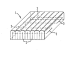
- In the drawing, a thermally insulating block 1, for use in lining the inner surfaces of a furnace wall, comprises a plurality of U-shaped strips 2 of a low thermal mass material which are secured together under compression by a
retaining thread 3. This retainingthread 3 passes along the outside surface of the U-shaped strip 2 at the left hand side of the block 1, through the block at four positions transversely with respect thereto, and along two portions of the outer surface of the U-shaped strip at the right hand end of the block. Thethread 3 retains the strips 2 under transverse compression and it is to be understood that any other suitable form of retaining means, such as, at least one transverse rod, may be used instead of thethread 3. - In a modified form of the block 1, a scrim cloth of the same material as that from which the strips 2 are made, is wrapped around the block, preferably leaving the opposed end faces of the U-shaped strips 2 exposed. Such wrapping can be adhesively secured to the block 1.
- In the manufacture of the block 1, a single layer of low thermal mass material, such as either of those described above and capable of withstanding respective operating temperatures of 1260°C (2300°F) and 1425°C (2600°F), has been folded to form an intermediate corrugated block. One major face of the intermediate block, has then had its corrugations truncated, thereby forming the plurality of side-by-side, generally U-shaped strips 2 which are subsequently subjected to a transverse compressional force. Alternatively, and as also indicated above, this truncation step may follow the compression and retaining steps.
- In this compressed state, the
thread 3 passes transversely through the strips 2 and is secured in a suitable manner to maintain the block 1 under compression. - It will be appreciated that such a block 1 could also be made by forming two or more intermediate blocks, of equal thickness, which may then be secured together in side-by-side relationship under compression.
- The or each block 1 can then be fixed to the internal surface of a furnace wall by cementing the planar, truncated face thereto. Also, it will be appreciated that the transversely compressing and maintaining under compression steps can be formed simultaneously, and preferably when the retaining means is in the form of a flexible thread or cord passing transversely through the side-by-side strips, whereby tightening or tensioning of the thread or
cord 3 actually compresses the strips together and, then, subsequently retains them in the compressed state.
Claims (13)
Priority Applications (1)
| Application Number | Priority Date | Filing Date | Title |
|---|---|---|---|
| AT83301228T ATE20496T1 (en) | 1982-03-27 | 1983-03-08 | THERMAL INSULATION MODULE. |
Applications Claiming Priority (2)
| Application Number | Priority Date | Filing Date | Title |
|---|---|---|---|
| GB8209080 | 1982-03-27 | ||
| GB8209080 | 1982-03-27 |
Publications (2)
| Publication Number | Publication Date |
|---|---|
| EP0090518A1 EP0090518A1 (en) | 1983-10-05 |
| EP0090518B1 true EP0090518B1 (en) | 1986-06-18 |
Family
ID=10529341
Family Applications (1)
| Application Number | Title | Priority Date | Filing Date |
|---|---|---|---|
| EP83301228A Expired EP0090518B1 (en) | 1982-03-27 | 1983-03-08 | Thermally insulating blocks |
Country Status (4)
| Country | Link |
|---|---|
| EP (1) | EP0090518B1 (en) |
| AT (1) | ATE20496T1 (en) |
| DE (1) | DE3364133D1 (en) |
| GB (1) | GB2117877B (en) |
Families Citing this family (2)
| Publication number | Priority date | Publication date | Assignee | Title |
|---|---|---|---|---|
| GB2190167B (en) * | 1986-05-09 | 1990-05-09 | Thomas James Twort | Furnace pipe insulation |
| DE4119990A1 (en) * | 1991-06-18 | 1992-12-24 | Forsch Anorganische Werkstoffe | Combination plate for ceramic firing kiln - incorporates wave-form or smooth fibre parts connected 0.5-3 mm thick ceramic cover plate |
Citations (1)
| Publication number | Priority date | Publication date | Assignee | Title |
|---|---|---|---|---|
| EP0018677A1 (en) * | 1979-04-13 | 1980-11-12 | Heattreatment Advising Company N.V. | Oven walls comprising panels made of ceramic fibre materials |
Family Cites Families (8)
| Publication number | Priority date | Publication date | Assignee | Title |
|---|---|---|---|---|
| GB1038498A (en) * | 1963-08-13 | 1966-08-10 | Steetley Refractory Brick Comp | Improvements in or relating to refractory units for use in lining metallurgical furnaces |
| US3819468A (en) * | 1971-06-28 | 1974-06-25 | Sander Ind Inc | High temperature insulation module |
| US3832815A (en) * | 1973-01-29 | 1974-09-03 | Flinn & Dreffein Eng Co | Modular insulation of fibrous material |
| GB1545842A (en) * | 1976-03-17 | 1979-05-16 | Johns Manville | Furnace lining apparatus |
| GB2004039B (en) * | 1977-05-13 | 1982-01-20 | Clinotherm Ltd | Furnaces and ovens |
| GB2004626B (en) * | 1977-09-22 | 1982-05-06 | Studweldpro Uk Ltd | Insulation materials |
| GB2070748A (en) * | 1980-03-04 | 1981-09-09 | Ductile Hot Mill Ltd | Panel for a furnace wall structure |
| US4339902A (en) * | 1980-06-30 | 1982-07-20 | Manville Service Corporation | Multiple layer thermal insulation device |
-
1983
- 1983-02-03 GB GB08302934A patent/GB2117877B/en not_active Expired
- 1983-03-08 EP EP83301228A patent/EP0090518B1/en not_active Expired
- 1983-03-08 AT AT83301228T patent/ATE20496T1/en not_active IP Right Cessation
- 1983-03-08 DE DE8383301228T patent/DE3364133D1/en not_active Expired
Patent Citations (1)
| Publication number | Priority date | Publication date | Assignee | Title |
|---|---|---|---|---|
| EP0018677A1 (en) * | 1979-04-13 | 1980-11-12 | Heattreatment Advising Company N.V. | Oven walls comprising panels made of ceramic fibre materials |
Also Published As
| Publication number | Publication date |
|---|---|
| DE3364133D1 (en) | 1986-07-24 |
| EP0090518A1 (en) | 1983-10-05 |
| GB8302934D0 (en) | 1983-03-09 |
| ATE20496T1 (en) | 1986-07-15 |
| GB2117877B (en) | 1985-05-09 |
| GB2117877A (en) | 1983-10-19 |
Similar Documents
| Publication | Publication Date | Title |
|---|---|---|
| US3993237A (en) | Method for providing high-temperature internal insulation | |
| US4339902A (en) | Multiple layer thermal insulation device | |
| AU3688184A (en) | Insulation means for piping subject to thermal hydrostatic and mechanical stresses | |
| CA1215831A (en) | Furnace wall construction for industrial use | |
| EP0090518B1 (en) | Thermally insulating blocks | |
| US4151693A (en) | Refractory/insulating modules and method of making same | |
| GB2004626A (en) | Insulation Materials | |
| US4574995A (en) | Method for protecting the walls of a furnace at high temperature | |
| GB2103331A (en) | Heat-insulating casing for elongate constructional parts | |
| US4344753A (en) | Method for reducing the thermal inertia of a furnace or oven wall and insulated wall produced thereby | |
| US4582742A (en) | High-temperature fibrous insulation module | |
| US4425749A (en) | Furnace lining module | |
| US6004890A (en) | Heat-resisting material | |
| US4802425A (en) | High temperature fiber system with controlled shrinkage and stress resistance | |
| JPS57149875A (en) | Refractory composite structure member having formed member comprising refractory material and high heat insulation layer or inflation compensating layer and manufacture | |
| US4900247A (en) | High-temperature heating furnace | |
| JPH0633950B2 (en) | Support structure for the ceiling of the furnace | |
| USRE32732E (en) | Method for providing high temperature internal insulation | |
| RU2118775C1 (en) | Method and system for lining spaces at high temperature | |
| US4457449A (en) | Pressure tank for hot fluids or agents | |
| JPH0217869Y2 (en) | ||
| CA1229228A (en) | Fireproof gas-permeable construction elements | |
| JPH0421818Y2 (en) | ||
| GB2058311A (en) | Modules for construction of furnaces | |
| SU846692A1 (en) | Web insulation material |
Legal Events
| Date | Code | Title | Description |
|---|---|---|---|
| PUAI | Public reference made under article 153(3) epc to a published international application that has entered the european phase |
Free format text: ORIGINAL CODE: 0009012 |
|
| AK | Designated contracting states |
Designated state(s): AT BE CH DE FR GB IT LI LU NL SE |
|
| 17P | Request for examination filed |
Effective date: 19831130 |
|
| RBV | Designated contracting states (corrected) |
Designated state(s): AT BE CH DE FR IT LI LU NL SE |
|
| ITF | It: translation for a ep patent filed |
Owner name: DE DOMINICIS & MAYER S.R.L. |
|
| GRAA | (expected) grant |
Free format text: ORIGINAL CODE: 0009210 |
|
| AK | Designated contracting states |
Kind code of ref document: B1 Designated state(s): AT BE CH DE FR IT LI LU NL SE |
|
| REF | Corresponds to: |
Ref document number: 20496 Country of ref document: AT Date of ref document: 19860715 Kind code of ref document: T |
|
| REF | Corresponds to: |
Ref document number: 3364133 Country of ref document: DE Date of ref document: 19860724 |
|
| ET | Fr: translation filed | ||
| PLBE | No opposition filed within time limit |
Free format text: ORIGINAL CODE: 0009261 |
|
| STAA | Information on the status of an ep patent application or granted ep patent |
Free format text: STATUS: NO OPPOSITION FILED WITHIN TIME LIMIT |
|
| 26N | No opposition filed | ||
| PGFP | Annual fee paid to national office [announced via postgrant information from national office to epo] |
Ref country code: AT Payment date: 19910313 Year of fee payment: 9 |
|
| PGFP | Annual fee paid to national office [announced via postgrant information from national office to epo] |
Ref country code: SE Payment date: 19910320 Year of fee payment: 9 Ref country code: FR Payment date: 19910320 Year of fee payment: 9 |
|
| ITTA | It: last paid annual fee | ||
| PGFP | Annual fee paid to national office [announced via postgrant information from national office to epo] |
Ref country code: NL Payment date: 19910331 Year of fee payment: 9 |
|
| PGFP | Annual fee paid to national office [announced via postgrant information from national office to epo] |
Ref country code: DE Payment date: 19910402 Year of fee payment: 9 |
|
| PGFP | Annual fee paid to national office [announced via postgrant information from national office to epo] |
Ref country code: LU Payment date: 19910403 Year of fee payment: 9 Ref country code: CH Payment date: 19910403 Year of fee payment: 9 |
|
| PGFP | Annual fee paid to national office [announced via postgrant information from national office to epo] |
Ref country code: BE Payment date: 19910503 Year of fee payment: 9 |
|
| EPTA | Lu: last paid annual fee | ||
| PG25 | Lapsed in a contracting state [announced via postgrant information from national office to epo] |
Ref country code: LU Free format text: LAPSE BECAUSE OF NON-PAYMENT OF DUE FEES Effective date: 19920308 Ref country code: AT Effective date: 19920308 |
|
| PG25 | Lapsed in a contracting state [announced via postgrant information from national office to epo] |
Ref country code: SE Effective date: 19920309 |
|
| PG25 | Lapsed in a contracting state [announced via postgrant information from national office to epo] |
Ref country code: LI Effective date: 19920331 Ref country code: CH Effective date: 19920331 Ref country code: BE Effective date: 19920331 |
|
| BERE | Be: lapsed |
Owner name: FUEL CONSERVATION SERVICES LTD Effective date: 19920331 |
|
| PG25 | Lapsed in a contracting state [announced via postgrant information from national office to epo] |
Ref country code: NL Effective date: 19921001 |
|
| NLV4 | Nl: lapsed or anulled due to non-payment of the annual fee | ||
| PG25 | Lapsed in a contracting state [announced via postgrant information from national office to epo] |
Ref country code: FR Effective date: 19921130 |
|
| REG | Reference to a national code |
Ref country code: CH Ref legal event code: PL |
|
| PG25 | Lapsed in a contracting state [announced via postgrant information from national office to epo] |
Ref country code: DE Effective date: 19921201 |
|
| REG | Reference to a national code |
Ref country code: FR Ref legal event code: ST |
|
| EUG | Se: european patent has lapsed |
Ref document number: 83301228.9 Effective date: 19921005 |