EP0089098B1 - Refractive-index responsive light-signal system - Google Patents
Refractive-index responsive light-signal system Download PDFInfo
- Publication number
- EP0089098B1 EP0089098B1 EP83200527A EP83200527A EP0089098B1 EP 0089098 B1 EP0089098 B1 EP 0089098B1 EP 83200527 A EP83200527 A EP 83200527A EP 83200527 A EP83200527 A EP 83200527A EP 0089098 B1 EP0089098 B1 EP 0089098B1
- Authority
- EP
- European Patent Office
- Prior art keywords
- light
- section
- refractive index
- liquid
- component
- Prior art date
- Legal status (The legal status is an assumption and is not a legal conclusion. Google has not performed a legal analysis and makes no representation as to the accuracy of the status listed.)
- Expired
Links
Images
Classifications
-
- G—PHYSICS
- G01—MEASURING; TESTING
- G01N—INVESTIGATING OR ANALYSING MATERIALS BY DETERMINING THEIR CHEMICAL OR PHYSICAL PROPERTIES
- G01N21/00—Investigating or analysing materials by the use of optical means, i.e. using sub-millimetre waves, infrared, visible or ultraviolet light
- G01N21/17—Systems in which incident light is modified in accordance with the properties of the material investigated
- G01N21/41—Refractivity; Phase-affecting properties, e.g. optical path length
- G01N21/43—Refractivity; Phase-affecting properties, e.g. optical path length by measuring critical angle
- G01N21/431—Dip refractometers, e.g. using optical fibres
-
- G—PHYSICS
- G01—MEASURING; TESTING
- G01F—MEASURING VOLUME, VOLUME FLOW, MASS FLOW OR LIQUID LEVEL; METERING BY VOLUME
- G01F23/00—Indicating or measuring liquid level or level of fluent solid material, e.g. indicating in terms of volume or indicating by means of an alarm
- G01F23/22—Indicating or measuring liquid level or level of fluent solid material, e.g. indicating in terms of volume or indicating by means of an alarm by measuring physical variables, other than linear dimensions, pressure or weight, dependent on the level to be measured, e.g. by difference of heat transfer of steam or water
- G01F23/28—Indicating or measuring liquid level or level of fluent solid material, e.g. indicating in terms of volume or indicating by means of an alarm by measuring physical variables, other than linear dimensions, pressure or weight, dependent on the level to be measured, e.g. by difference of heat transfer of steam or water by measuring the variations of parameters of electromagnetic or acoustic waves applied directly to the liquid or fluent solid material
- G01F23/284—Electromagnetic waves
- G01F23/292—Light, e.g. infrared or ultraviolet
- G01F23/2921—Light, e.g. infrared or ultraviolet for discrete levels
Definitions
- the present invention relates to a device for providing a light signal indicative of the refractive index of a liquid and for detecting the presence of gas bubbles therein.
- a fluid medium which may be either discontinuous changes (for example the formation of bubbles in a liquid) or continuous changes affecting the physical or chemical properties of this fluid (for example the concentration of solute in a solution or of one of the constituents of a fluid mixture or temperature variations in a fluid).
- Such detection may be used for various applications such as carrying out measurements, control or testing operations and regulation.
- bubbles may be sensed in a chemical or fermentation process, the optical probe being of the type having a single light guide with a reflective end.
- the present invention has an object to avoid the disadvantages of the prior art and to provide a simple device of significant increased sensitivity for detecting both discontinuous changes occurring in a fluid resulting from the evolution of gas bubbles, and continuous variations of some characteristic of this fluid related to its refractive index.
- the present invention is specifically defined in claim 1.
- the device of the present invention can thus be used for detecting the presence or absence of said fluid, for measuring the refractive index of said fluid and for detecting the presence of bubbles in said fluid.
- elongate light-conducting body or “light guide” are understood to cover any elongate body capable of conveying light by multiple internal reflections.
- a light guide comprising an intermediate curved section of several (at least two) alternating curvatures provides the advantage of imparting to the present device a particularly high sensitivity (the degree of sensitivity of such structure can be determined by the variation of the refractive index of the fluid to be measured), and in any case notably higher than that which can be obtained with a structure with a single curvature (whether it be U-shaped or with a curvature of at least 360°).
- the intermediate section with alternating curvatures of the light guide may be given various forms, so long as the different bends or curvatures of this intermediate section remain successively arranged in such a manner that each of these bends or curvatures be always bent in a direction opposite to adjacent curvatures.
- one may use a structure with a double curvature, wherein the last curvature is bent in an opposite direction relative to the first curvature, or with a triple curvature wherein the middle curvature is bent in an opposite direction to the first and last curvatures, or else a structure having an even greater number of curvatures.
- the different bends or curvatures may moreover be mutually connected by intermediate straight portions, or on the other hand be directly adjoining (directly connected without being separated from each other by straight portions).
- these straight portions will moreover be advantageously chosen so that their length remains relatively small with respect to the dimensions of the curvatures to which they are connected.
- curvatures can be used with a variable radius which can either increase or decrease progressively.
- the radius of curvature R of the different curved portions can advantageously be chosen small in relation to the transverse dimensions of the light guide and thereby provide a greater effect than curvatures with large radii.
- radii of curvature of the different alternating curvatures will preferably be chosen, for a given cylindrical light guide of cross-sectional radius r, so that the ratio R/r lies between about 3 and 5.
- this rod can be made of any appropriate transparent material.
- this material When the material must be chosen, in the case where the device is used to determine continuous index variations, this material must have a higher index of refraction than that of the measured liquid; . when, however, the device is used as a level indicator, it may have any index of refraction, greater or less than that of the measured liquid.
- the size of the cross-section of the light-conducting rod with alternating curvatures is of little importance, since it is the ratio R/r of the radius of curvature R of the different curvatures to the cross-sectional radius r of the rod which is in fact the determining factor for achieving the desired effect.
- R/r the ratio of the radius of curvature R of the different curvatures to the cross-sectional radius r of the rod which is in fact the determining factor for achieving the desired effect.
- this cross-section be circular, and one may very well envisage using rods with a square, hexagonal, elliptic cross-section (in such a case the radius of curvature R must be sufficiently small with respect to the cross-sectional rod dimension in the plane of curvature).
- a light guiding consisting of an optical fiber one can in principle use any appropriate type of fiber (these fibers may, moreover, be made of glass-based or plastic- based materials). However, it is particularly advantageous to choose more especially so- called step-index fibers.
- the presence of a cladding around the light-conducting core presents the additional advantage of preventing, in non-curved parts of the fiber, any risk of the disturbing influence of a parasitic medium which may possibly be present.
- the intermediate section one may moreover envisage either to strip the fiber completely of its cladding, so as to permit direct contact of the central core with the fluid medium to be tested, or on the other hand to leave it completely protected by its cladding.
- angle of incidence of a light ray on a surface will moreover be used according to its usual definition, namely the angle which this incident light ray makes with respect to the normal to this surface. According to this definition, an increase of obliquity of the incident light ray with respect to the surface is equivalent to a decrease of its angle of incidence.
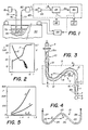
- the device of Fig. 1 is used for testing the state of charge of a conventional lead-acid storate battery and to detect the presence of gas bubbles within the liquid medium.
- This bubble-effect detector is used to detect bubbling during charge and hence as an overcharge-warning device, since overcharging results in the development of bubbles of gas within the electrolyte.
- Fig. 1 shows such a bubble detector serving as an overcharge-warning device and comprising a fiber-optical light pipe 75 having an input section or stretch 76, an output section or stretch 77 and a multiply-curved Q-shaped intermediate section 78 immersed in the electrolyte 79 of a lead-acid battery 80.
- the free end of the input section 76 is provided with a light source 81 injecting a beam of light into this end of the fiber while the opposite end of the fiber is provided with a photoelectric transducer 82 whose output s is an electrical signal representing the light intensity emerging at the output section 77.
- the light source 81 can be constituted by a LED while the transducer 82 is constituted by a photodiode.
- the variation of the electrical signal s as a function of the state of charge of the battery 80 is represented by the curve E in Fig. 2 in which signal current is plotted along one ordinate against time along the abscissa.
- the other curve F of this diagram illustrates the charging as a function of time, i.e. the voltage V plotted along the other ordinate which rises during charging from about 1.7 volts to about 2.7 volts at the end of the charge. At the upper plateau gas bubbling results.
- the curve E shows that the electrical signal s is constituted by a first component slowly decreasing with time, characteristic of the index of refraction and thus the state of charge which levels off just before the end of charging at, say, 2.5 volts, and a second discontinuous component varying rapidly with time and representing the development of bubbling and the arrival of bubbles at the section 78 of the optical fiber 75.
- Each temporary contact of a bubble of gas with the sensing portion 78 appears to sharply increase the luminous transmission through the fiber 75.
- the original signal s is applied to an electronic evaluating circuit 83 adapted to analyze the signal s to detect the presence of the discontinuous second component representing gas evolutions.
- the circuit 83 comprises a signal amplifier 84 directly connected to the output of the transducer 82 and amplifying the signal s.
- a filter 85 connected to the amplifier 84 separates the two components of the signal and passes only the high-frequency component which is applied to an integrator/level discriminator 86 connected to the output of the filter 85 for generating a warning signal when this second component, as integrated, exceeds a predetermined threshold value intended to prevent the generation of the warning signal by transient parasitic fluctuations urelated to the formation of gas bubbles on overcharge.
- This signal is applied to a display device 87, e.g. a LED, and to the control circuit for the charger 89 to terminate the charging operation.
- the first component of the signal can be applied to a display 88 affording a continuous indication of the state of charge.
- Fig. 3 illustrates a gauge usable to modify the apparatus of Fig. 1 which comprises a light guide consisting of a simple transparent rod provided with two alternating curvatures bent in opposite directions.
- the device represented in this figure has a rod 10 made of a transparent material, which consists of an intermediate curved, S-shaped section 11 and of two straight sections 15 and 16 extending substantially vertically from each of the ends of this curved section 11.
- the straight sections 15 and 16 are intended to respectively serve as an input section and an output section for the rod 1.
- the S-shaped section 11 consists of two successive curved portions 12 and 13 both in the form of an arc of a circle connected to each other by an intermediate straight portion 14, these two curved portions 12 and 13 being moreover arranged in a substantially symmetrical manner with respect to each other, while being bent in opposite directions to each other.
- the transparent rod 10 has a circular cross-section of radius r, while the curved portions 12 and 13 have a constant radius of curvature R.
- a light source 5 adapted to inject light into the transparent rod 10 while in the vicinity of the endface 16a of the output section 16, there is arranged a detection system 6 adapted to determine the light intensity transmitted by the rod 10.
- This detection system 6 consists of a photo-electric detector 7 electrically connected to a measurement and/or display device 8.
- the curved section of this device is adapted to be immersed in a liquid 9 with a refractive index n, of which one of the characteristics linked to this refractive index is to be determined.
- the transparent material of the rod 10 is chosen so as to have a refractive index n 1 greater than the refractive index n of the liquid to be tested.
- the first curvature 12 of this curved section 11 has the effect of modifying the incidence of the rays which strike its walls, while causing, in particular, a reduction of the angle of incidence of those rays which strike its outer surface (this reduction of the angle of incidence being moreover a function of the magnitude of the curvature), so that incident rays whose angle exceeds the critical angle with respect to the surrounding liquid 9 are then forced to pass by refraction into the liquid (behavior illustrated by the ray p i in the drawings).
- this reduction of the incidence is nevertheless not identical for all the rays which arrive with the same incidence in this curved portion 12, since it depends on the depth at which these rays have been able to penetrate into this curved portion before striking its outer surface, so that only a part of the rays which arrive under the same incidence is liable to pass out of the rod 10 by refraction into the surrounding liquid.
- the proportion of rays which are liable to be refracted out into the surrounding liquid is evidently a function of the refractive index of this liquid, since the critical angle of total reflection depends on this index.
- the proportion of the rays forced to pass by refraction into the surrounding liquid is evidently a function of the refractive index of this liquid, given that the critical angle of total reflection here also depends on this index.
- the intensity of the light thus emerging at the other end 16a of the rod which is substantially equal to the intensity of the light injected into the rod minus the losses due to refraction occurring primarily in the curved portions 12 and 13 (aside from the absorption losses in the rod), is thus likewise a function of the refractive index of the medium surrounding the curved section.
- This transmitted light intensity hence provides a light signal which is characteristic of and corresponds to the refractive index of the medium surrounding the curved section of the rod.
- Fig. 4 illustrates another form of light conducting body which may be used in the described embodiment according to Fig. 3 which consists of a transparent rod 21 having three alternating curvatures.
- the rod 21 in the general shape of a W, shown in this figure consists of three curved portions 22, 23 and 24 each in the form of an arc of a circle respectively connected to one another by two intermediate portions 25 and 26 (the curved middle portion 23 being bent in the opposite direction to the outer curvatures 22 and 24), the free ends of the outer curvatures 22 and 24 moreover being prolonged by straight portions 27 and 28.
- a refractometer The fields of application of such a refractometer are manifold: chemical industry, medical field, instrumentation in general, automobile or aeronautic instrumentation, etc. In the field of automobile instrumentation, one may consider using this refractometer for applications such as determination of the state of charge of a lead acid battery or determination of the concentration of an anti-freeze mixture.
- this first application to a battery one can determine the state of the conventional lead-acid battery by measuring the variations of the refractive index of the electrolyte, this index falling from 1.378 at full charge to 1.348 when the battery is discharged; the diagram of Fig.
Landscapes
- Physics & Mathematics (AREA)
- General Physics & Mathematics (AREA)
- Electromagnetism (AREA)
- Analytical Chemistry (AREA)
- Fluid Mechanics (AREA)
- Health & Medical Sciences (AREA)
- Life Sciences & Earth Sciences (AREA)
- Chemical & Material Sciences (AREA)
- Thermal Sciences (AREA)
- Biochemistry (AREA)
- General Health & Medical Sciences (AREA)
- Immunology (AREA)
- Pathology (AREA)
- Investigating Or Analysing Materials By Optical Means (AREA)
- Measurement Of Levels Of Liquids Or Fluent Solid Materials (AREA)
- Indication And Recording Devices For Special Purposes And Tariff Metering Devices (AREA)
Applications Claiming Priority (2)
| Application Number | Priority Date | Filing Date | Title |
|---|---|---|---|
| US81351 | 1979-10-03 | ||
| US06/081,351 US4240747A (en) | 1979-10-03 | 1979-10-03 | Refractive-index responsive light-signal system |
Related Parent Applications (1)
| Application Number | Title | Priority Date | Filing Date |
|---|---|---|---|
| EP80810304.8 Division | 1980-09-30 |
Publications (3)
| Publication Number | Publication Date |
|---|---|
| EP0089098A2 EP0089098A2 (en) | 1983-09-21 |
| EP0089098A3 EP0089098A3 (en) | 1984-01-11 |
| EP0089098B1 true EP0089098B1 (en) | 1986-01-02 |
Family
ID=22163601
Family Applications (2)
| Application Number | Title | Priority Date | Filing Date |
|---|---|---|---|
| EP83200527A Expired EP0089098B1 (en) | 1979-10-03 | 1980-09-30 | Refractive-index responsive light-signal system |
| EP80810304A Expired EP0027099B1 (en) | 1979-10-03 | 1980-09-30 | Refractive-index responsive light-signal system |
Family Applications After (1)
| Application Number | Title | Priority Date | Filing Date |
|---|---|---|---|
| EP80810304A Expired EP0027099B1 (en) | 1979-10-03 | 1980-09-30 | Refractive-index responsive light-signal system |
Country Status (4)
| Country | Link |
|---|---|
| US (1) | US4240747A (enExample) |
| EP (2) | EP0089098B1 (enExample) |
| JP (2) | JPS5673335A (enExample) |
| DE (1) | DE3071312D1 (enExample) |
Families Citing this family (54)
| Publication number | Priority date | Publication date | Assignee | Title |
|---|---|---|---|---|
| CH652825A5 (fr) | 1980-09-18 | 1985-11-29 | Battelle Memorial Institute | Dispositif a double sonde optique pour determiner l'indice de refraction d'un fluide ramene a une temperature de reference predeterminee. |
| US4366431A (en) * | 1980-12-03 | 1982-12-28 | Ehv Systems, Inc. | Battery gassing detector |
| US4388583A (en) * | 1981-03-06 | 1983-06-14 | Outboard Marine Corporation | Battery charger with transducer for controlling charge rate |
| DE3232059A1 (de) * | 1981-09-04 | 1983-03-24 | Westinghouse Electric Corp., 15222 Pittsburgh, Pa. | Glasfaserdetektor |
| DE3311202A1 (de) * | 1982-03-31 | 1983-10-06 | Nippon Beet Sugar Mfg | Geraet zur bestimmung der dichte, der konzentration, des spezifischen gewichtes und dergleichen einer fluessigkeit |
| DE3217168C2 (de) * | 1982-05-07 | 1986-10-30 | Fraunhofer-Gesellschaft zur Förderung der angewandten Forschung e.V., 8000 München | Faseroptisches Refraktometer |
| IL67679A (en) * | 1983-01-14 | 1987-08-31 | Jerusalem College Tech | Refractometer for fluids |
| US4682889A (en) * | 1983-08-03 | 1987-07-28 | Stanley Electric Co., Ltd. | Refractometer for measuring the refractive index of a liquid |
| EP0274771B1 (en) * | 1984-01-20 | 1991-12-27 | Hughes Aircraft Company | Liquid level sensor |
| JPS61196139A (ja) * | 1985-02-27 | 1986-08-30 | Nippon Kokan Kk <Nkk> | 屈折率測定プロ−ブ |
| US4659218A (en) * | 1985-05-23 | 1987-04-21 | Canadian Patents & Development Corporation | Multi-probe system for measuring bubble characteristics gas hold-up, liquid hold-up and solid hold-up in a three-phase fluidized bed |
| US4788436A (en) * | 1986-12-24 | 1988-11-29 | Walter Koechner | Radiation sensitive optical fiber and detector |
| GB8723359D0 (en) * | 1987-10-05 | 1987-11-11 | Atomic Energy Authority Uk | Sensor |
| US4797550A (en) * | 1987-11-06 | 1989-01-10 | Consolidation Coal Company | Fiber optic detector for flotation cell processing |
| US4860551A (en) * | 1987-12-29 | 1989-08-29 | Whirlpool Corporation | Frost sensor for an appliance |
| US4880990A (en) * | 1988-06-13 | 1989-11-14 | Imo Industries, Inc. | Optical liquid-level sensing apparatus |
| JP2657673B2 (ja) * | 1988-08-11 | 1997-09-24 | 石油公団 | 水中油・ガス漏洩検知装置 |
| US5041990A (en) * | 1989-01-10 | 1991-08-20 | Mitsubishi Oil Co., Ltd. | Method and apparatus for measuring entrained gas bubble content of flowing fluid |
| US5141310A (en) * | 1991-03-28 | 1992-08-25 | Miles Inc. | Methods and devices for measuring the specific gravity of liquids |
| GB9111776D0 (en) * | 1991-05-31 | 1991-07-24 | De Beers Ind Diamond | Determination of the condition of or change in state of an environment |
| JPH0518814U (ja) * | 1991-07-31 | 1993-03-09 | 株式会社新潟鐵工所 | 射出成形機用分割シユータ |
| US5235179A (en) * | 1991-09-24 | 1993-08-10 | Hughes Aircraft Company | Evanescent wave liquid level sensor with density compensation |
| US5308162A (en) * | 1992-02-13 | 1994-05-03 | Fujikura Ltd. | Temperature abnormality detecting structure for fluid pipe |
| US5311274A (en) * | 1992-05-11 | 1994-05-10 | Cole Jr Charles F | Fiber optic refractometer |
| SE501108C2 (sv) * | 1993-04-08 | 1994-11-14 | Pharmacia Lkb Biotech | Sätt och anordning för bestämning av brytningsindex |
| SE9602960D0 (sv) * | 1996-08-09 | 1996-08-09 | Siemens Elema Ab | Narkosvätskeidentifiering |
| JPH10116871A (ja) * | 1996-10-14 | 1998-05-06 | Yamaha Corp | 窒化チタン膜評価法とタングステン膜形成法 |
| US6538739B1 (en) * | 1997-09-30 | 2003-03-25 | The Regents Of The University Of California | Bubble diagnostics |
| US5949219A (en) * | 1998-07-24 | 1999-09-07 | The United States Of America As Represented By The United States Department Of Energy | Optical state-of-charge monitor for batteries |
| US6687004B1 (en) | 1999-10-22 | 2004-02-03 | Marquette University | Optical sensor for opaque and non-opaque materials |
| US6728430B1 (en) * | 2002-01-09 | 2004-04-27 | Raytheon Company | Fluid identification system |
| CA2424820C (en) * | 2003-04-08 | 2010-06-22 | Institut National D'optique | Prismatic reflection optical waveguide device |
| US7106429B2 (en) * | 2004-01-27 | 2006-09-12 | Georgia Tech Research Corporation | Apparatus and method for detecting change of dielectric constant |
| US8576603B2 (en) * | 2004-11-15 | 2013-11-05 | Nxp, B.V. | Flash- and ROM-memory |
| USD570296S1 (en) | 2006-01-10 | 2008-06-03 | Wipf Daniel D | Level sensing switch |
| JP5328573B2 (ja) * | 2009-09-03 | 2013-10-30 | 三菱電機株式会社 | アイドルストップ制御装置およびアイドルストップ制御方法 |
| JP5349245B2 (ja) * | 2009-10-16 | 2013-11-20 | 東京瓦斯株式会社 | 貯蔵タンク内の液密度計測装置 |
| JP5349368B2 (ja) * | 2010-03-01 | 2013-11-20 | 東京瓦斯株式会社 | 貯蔵タンク内の液密度計測装置 |
| DE102011102204B4 (de) | 2010-06-05 | 2017-11-16 | Drägerwerk AG & Co. KGaA | Anästhesiesystem mit abnehmbarer Anästesiemittel-Dosiervorrichtung |
| FR3000547B1 (fr) * | 2012-12-27 | 2016-02-12 | Centre Nat Rech Scient | Procede et dispositif pour caracteriser un milieu fluide a l'aide d'un transducteur photoelectrique |
| US9553465B2 (en) * | 2014-04-21 | 2017-01-24 | Palo Alto Research Center Incorporated | Battery management based on internal optical sensing |
| US20150308952A1 (en) * | 2014-04-23 | 2015-10-29 | Littelfuse, Inc. | Urea concentration sensor |
| US9677916B2 (en) | 2014-07-15 | 2017-06-13 | Palo Alto Research Center Incorporated | Energy system monitoring |
| US10446886B2 (en) | 2014-07-23 | 2019-10-15 | Palo Alto Research Center Incorporated | Embedded fiber optic cables for battery management |
| US10403922B2 (en) | 2014-07-23 | 2019-09-03 | Palo Alto Research Center Incorporated | Battery with embedded fiber optic cable |
| CN105444839B (zh) * | 2015-11-18 | 2019-09-20 | 中北大学 | 基于光时域反射技术的塑料光纤液位传感器及测量方法 |
| US20200408680A1 (en) * | 2016-07-25 | 2020-12-31 | Joseph Samuel Accetta | Optical immersion refractometer probe |
| US10317256B2 (en) | 2017-04-14 | 2019-06-11 | Palo Alto Research Center Incorporated | Monitoring transportation systems |
| EP3587202B1 (en) * | 2018-06-29 | 2023-04-05 | Volvo Car Corporation | System and method for determinig water content in brake fluid |
| GB2576773A (en) * | 2018-08-31 | 2020-03-04 | Advanced Fibreoptic Eng Ltd | Fluid level sensing device and method |
| EP3983780B1 (en) * | 2019-06-11 | 2023-04-19 | Scully Signal Company | Method and device for characterizing a medium using refractive index |
| IT202100003566A1 (it) * | 2021-02-18 | 2021-05-18 | Congenio S R L S | Dispositivo a risparmio energetico atto al monitoraggio di batterie elettriche del tipo al piombo acido |
| GB2616457A (en) * | 2022-03-09 | 2023-09-13 | Draexlmaier Lisa Gmbh | Optical liquid detection system |
| CN117603632B (zh) * | 2024-01-23 | 2024-04-09 | 上海精珅新材料有限公司 | 一种含有uv增粘胶水的胶带制备方法 |
Family Cites Families (8)
| Publication number | Priority date | Publication date | Assignee | Title |
|---|---|---|---|---|
| US3282149A (en) * | 1963-04-10 | 1966-11-01 | American Cyanamid Co | Linear photoelectric refractometer |
| DE1927330A1 (de) * | 1968-05-30 | 1970-01-29 | Atomic Power Const Ltd | Gemischdurchflussanalysator |
| US3648521A (en) * | 1968-10-23 | 1972-03-14 | Pasquale J Amendolia | Light indicator |
| DE2034344A1 (de) * | 1970-07-10 | 1972-01-13 | Ulrich H | Einrichtung zur Messung physikalischer Großen durch Messung der Intensität eines Lichtstrahlenbundels |
| US3915570A (en) * | 1970-08-20 | 1975-10-28 | Environment One Corp | Optical fluid contamination and change monitor method and apparatus |
| FR2130037A1 (enExample) | 1971-03-25 | 1972-11-03 | Danel M F | |
| DE2314827A1 (de) * | 1973-03-24 | 1974-09-26 | Bayer Ag | Verfahren und vorrichtung zum saeubern und heranfuehren von messtoffen in einen messkopf sowie automatisches saeubern dieses messkopfes |
| DE2860995D1 (en) * | 1977-07-01 | 1981-11-26 | Battelle Memorial Institute | Device for generating a light signal characteristic of the refractive index of a fluidand and its use |
-
1979
- 1979-10-03 US US06/081,351 patent/US4240747A/en not_active Expired - Lifetime
-
1980
- 1980-09-30 DE DE8080810304T patent/DE3071312D1/de not_active Expired
- 1980-09-30 EP EP83200527A patent/EP0089098B1/en not_active Expired
- 1980-09-30 EP EP80810304A patent/EP0027099B1/en not_active Expired
- 1980-10-02 JP JP13680480A patent/JPS5673335A/ja active Granted
-
1985
- 1985-08-23 JP JP60184324A patent/JPS6170443A/ja active Granted
Non-Patent Citations (1)
| Title |
|---|
| "Elektronik", vol. 25, no. 8, August 1976, page 93, "Sonde zählt Bläschen in Flüssigkeiten" * |
Also Published As
| Publication number | Publication date |
|---|---|
| EP0027099B1 (en) | 1985-12-27 |
| EP0089098A2 (en) | 1983-09-21 |
| JPS6110774B2 (enExample) | 1986-03-31 |
| EP0089098A3 (en) | 1984-01-11 |
| US4240747A (en) | 1980-12-23 |
| JPS5673335A (en) | 1981-06-18 |
| EP0027099A1 (en) | 1981-04-15 |
| JPS6170443A (ja) | 1986-04-11 |
| JPS6134091B2 (enExample) | 1986-08-06 |
| DE3071312D1 (en) | 1986-02-06 |
Similar Documents
| Publication | Publication Date | Title |
|---|---|---|
| EP0089098B1 (en) | Refractive-index responsive light-signal system | |
| US4187025A (en) | Device for producing a light signal corresponding to the refractive index of a fluid | |
| US4942306A (en) | Fibre optic sensor for the continuous measurement liquids level and other parameters | |
| US5005005A (en) | Fiber optic probe system | |
| US6205263B1 (en) | Distributed optical fiber sensor with controlled response | |
| US4298794A (en) | Fiber optic hot spot detector | |
| CN105911025A (zh) | 一种分布式螺旋芯光纤表面等离子体共振传感器及其测量方法 | |
| EP0334533B1 (en) | Fibre optic discrete or continuous liquid level sensor | |
| EP0145343B1 (en) | Optical fibre test method and apparatus for performing the method | |
| KR940003737B1 (ko) | 광섬유 연료 및 액체 게이지 | |
| US4678327A (en) | Method for inspecting an optical fiber | |
| Betta et al. | A digital liquid level transducer based on optical fiber | |
| US10145789B2 (en) | Immersion refractometer | |
| EP2431730B1 (en) | Device for discriminating between different fluids based on their refractive index | |
| Hancke | A fiber-optic density sensor for monitoring the state-of-charge of a lead acid battery | |
| US4988863A (en) | Optical fiber refractometer launching light at a non-zero launch angle | |
| JP2007071863A (ja) | 光学式センサ及び流体測定方法 | |
| Waluyo et al. | Testing and development of plastic optical fiber as humidity and temperature sensor | |
| EP0245091A1 (en) | Method of and apparatus for fiber optic sensing | |
| KR820000672B1 (ko) | 유체의 굴절률에 대응하는 광신호 발생장치 | |
| RU2399887C1 (ru) | Волоконно-оптический уровнемер и способ его изготовления | |
| SU1755123A1 (ru) | Оптоволоконный рефрактометр | |
| Stewart et al. | Chemical Sensing By Evanescent Field Absorption: The Sensitivity Of Optical Waveguides. | |
| CN109668652A (zh) | 一种玻璃管填充的光纤温度测量装置 | |
| Chen et al. | Power loss characteristics of a sensing element based on a grooved polymer optical fiber under elongation |
Legal Events
| Date | Code | Title | Description |
|---|---|---|---|
| PUAI | Public reference made under article 153(3) epc to a published international application that has entered the european phase |
Free format text: ORIGINAL CODE: 0009012 |
|
| 17P | Request for examination filed |
Effective date: 19830424 |
|
| AC | Divisional application: reference to earlier application |
Ref document number: 27099 Country of ref document: EP |
|
| AK | Designated contracting states |
Designated state(s): AT BE CH DE FR GB IT LI LU NL SE |
|
| PUAL | Search report despatched |
Free format text: ORIGINAL CODE: 0009013 |
|
| AK | Designated contracting states |
Designated state(s): AT BE CH DE FR GB IT LI LU NL SE |
|
| GRAA | (expected) grant |
Free format text: ORIGINAL CODE: 0009210 |
|
| RAP1 | Party data changed (applicant data changed or rights of an application transferred) |
Owner name: STANLEY ELECTRIC CO., LTD. |
|
| AC | Divisional application: reference to earlier application |
Ref document number: 27099 Country of ref document: EP |
|
| AK | Designated contracting states |
Designated state(s): AT BE CH DE FR GB IT LI LU NL SE |
|
| REF | Corresponds to: |
Ref document number: 17278 Country of ref document: AT Date of ref document: 19860115 Kind code of ref document: T |
|
| REF | Corresponds to: |
Ref document number: 3071328 Country of ref document: DE Date of ref document: 19860213 |
|
| ITF | It: translation for a ep patent filed | ||
| ET | Fr: translation filed | ||
| PLBE | No opposition filed within time limit |
Free format text: ORIGINAL CODE: 0009261 |
|
| STAA | Information on the status of an ep patent application or granted ep patent |
Free format text: STATUS: NO OPPOSITION FILED WITHIN TIME LIMIT |
|
| 26N | No opposition filed | ||
| ITTA | It: last paid annual fee | ||
| PGFP | Annual fee paid to national office [announced via postgrant information from national office to epo] |
Ref country code: CH Payment date: 19920925 Year of fee payment: 13 |
|
| PGFP | Annual fee paid to national office [announced via postgrant information from national office to epo] |
Ref country code: FR Payment date: 19930716 Year of fee payment: 14 |
|
| PGFP | Annual fee paid to national office [announced via postgrant information from national office to epo] |
Ref country code: AT Payment date: 19930802 Year of fee payment: 14 |
|
| PGFP | Annual fee paid to national office [announced via postgrant information from national office to epo] |
Ref country code: SE Payment date: 19930804 Year of fee payment: 14 |
|
| PGFP | Annual fee paid to national office [announced via postgrant information from national office to epo] |
Ref country code: BE Payment date: 19930805 Year of fee payment: 14 |
|
| PGFP | Annual fee paid to national office [announced via postgrant information from national office to epo] |
Ref country code: LU Payment date: 19930908 Year of fee payment: 14 |
|
| PG25 | Lapsed in a contracting state [announced via postgrant information from national office to epo] |
Ref country code: LI Effective date: 19930930 Ref country code: CH Effective date: 19930930 |
|
| EPTA | Lu: last paid annual fee | ||
| REG | Reference to a national code |
Ref country code: CH Ref legal event code: PL |
|
| PG25 | Lapsed in a contracting state [announced via postgrant information from national office to epo] |
Ref country code: LU Free format text: LAPSE BECAUSE OF NON-PAYMENT OF DUE FEES Effective date: 19940930 Ref country code: BE Effective date: 19940930 Ref country code: AT Effective date: 19940930 |
|
| PGFP | Annual fee paid to national office [announced via postgrant information from national office to epo] |
Ref country code: NL Payment date: 19940930 Year of fee payment: 15 |
|
| PG25 | Lapsed in a contracting state [announced via postgrant information from national office to epo] |
Ref country code: SE Effective date: 19941001 |
|
| EAL | Se: european patent in force in sweden |
Ref document number: 83200527.6 |
|
| BERE | Be: lapsed |
Owner name: STANLEY ELECTRIC CO. LTD Effective date: 19940930 |
|
| PG25 | Lapsed in a contracting state [announced via postgrant information from national office to epo] |
Ref country code: FR Effective date: 19950531 |
|
| EUG | Se: european patent has lapsed |
Ref document number: 83200527.6 |
|
| REG | Reference to a national code |
Ref country code: FR Ref legal event code: ST |
|
| PG25 | Lapsed in a contracting state [announced via postgrant information from national office to epo] |
Ref country code: NL Effective date: 19960401 |
|
| NLV4 | Nl: lapsed or anulled due to non-payment of the annual fee |
Effective date: 19960401 |
|
| PGFP | Annual fee paid to national office [announced via postgrant information from national office to epo] |
Ref country code: GB Payment date: 19960923 Year of fee payment: 17 |
|
| PGFP | Annual fee paid to national office [announced via postgrant information from national office to epo] |
Ref country code: DE Payment date: 19960927 Year of fee payment: 17 |
|
| PG25 | Lapsed in a contracting state [announced via postgrant information from national office to epo] |
Ref country code: GB Free format text: LAPSE BECAUSE OF NON-PAYMENT OF DUE FEES Effective date: 19970930 |
|
| GBPC | Gb: european patent ceased through non-payment of renewal fee |
Effective date: 19970930 |
|
| PG25 | Lapsed in a contracting state [announced via postgrant information from national office to epo] |
Ref country code: DE Free format text: LAPSE BECAUSE OF NON-PAYMENT OF DUE FEES Effective date: 19980701 |