EP0087179B1 - Method and device for moulding a transparent object - Google Patents
Method and device for moulding a transparent object Download PDFInfo
- Publication number
- EP0087179B1 EP0087179B1 EP83200141A EP83200141A EP0087179B1 EP 0087179 B1 EP0087179 B1 EP 0087179B1 EP 83200141 A EP83200141 A EP 83200141A EP 83200141 A EP83200141 A EP 83200141A EP 0087179 B1 EP0087179 B1 EP 0087179B1
- Authority
- EP
- European Patent Office
- Prior art keywords
- radiation
- moulding
- moulds
- transparent
- lens
- Prior art date
- Legal status (The legal status is an assumption and is not a legal conclusion. Google has not performed a legal analysis and makes no representation as to the accuracy of the status listed.)
- Expired
Links
- 238000000465 moulding Methods 0.000 title claims abstract description 46
- 238000000034 method Methods 0.000 title claims abstract description 26
- 230000005855 radiation Effects 0.000 claims abstract description 50
- 238000009826 distribution Methods 0.000 claims abstract description 24
- 239000000463 material Substances 0.000 claims abstract description 18
- 239000011521 glass Substances 0.000 claims description 11
- 239000012780 transparent material Substances 0.000 claims description 10
- 239000007788 liquid Substances 0.000 claims description 7
- 238000001514 detection method Methods 0.000 claims description 6
- 239000005337 ground glass Substances 0.000 claims description 5
- 238000011896 sensitive detection Methods 0.000 claims description 5
- 238000012545 processing Methods 0.000 claims description 4
- 230000000694 effects Effects 0.000 claims description 3
- 239000000126 substance Substances 0.000 claims description 3
- 230000001419 dependent effect Effects 0.000 claims description 2
- 239000007779 soft material Substances 0.000 claims description 2
- 229920002994 synthetic fiber Polymers 0.000 claims 3
- 230000006835 compression Effects 0.000 claims 1
- 238000007906 compression Methods 0.000 claims 1
- 230000008676 import Effects 0.000 claims 1
- 238000004519 manufacturing process Methods 0.000 description 14
- 230000003287 optical effect Effects 0.000 description 10
- 229920003023 plastic Polymers 0.000 description 9
- 239000004033 plastic Substances 0.000 description 8
- 230000005499 meniscus Effects 0.000 description 4
- 238000000748 compression moulding Methods 0.000 description 3
- 230000006399 behavior Effects 0.000 description 2
- 238000001816 cooling Methods 0.000 description 2
- 238000005498 polishing Methods 0.000 description 2
- NIXOWILDQLNWCW-UHFFFAOYSA-M Acrylate Chemical compound [O-]C(=O)C=C NIXOWILDQLNWCW-UHFFFAOYSA-M 0.000 description 1
- 230000015572 biosynthetic process Effects 0.000 description 1
- 239000000969 carrier Substances 0.000 description 1
- 230000000295 complement effect Effects 0.000 description 1
- 239000002131 composite material Substances 0.000 description 1
- 150000001875 compounds Chemical class 0.000 description 1
- 238000007796 conventional method Methods 0.000 description 1
- 238000004132 cross linking Methods 0.000 description 1
- 230000007423 decrease Effects 0.000 description 1
- 230000003247 decreasing effect Effects 0.000 description 1
- 238000011161 development Methods 0.000 description 1
- 230000018109 developmental process Effects 0.000 description 1
- 238000006073 displacement reaction Methods 0.000 description 1
- 230000006870 function Effects 0.000 description 1
- 238000010438 heat treatment Methods 0.000 description 1
- 238000005259 measurement Methods 0.000 description 1
- 239000000178 monomer Substances 0.000 description 1
- 238000006116 polymerization reaction Methods 0.000 description 1
- 230000000717 retained effect Effects 0.000 description 1
- 230000003746 surface roughness Effects 0.000 description 1
- 230000000007 visual effect Effects 0.000 description 1
- 238000011179 visual inspection Methods 0.000 description 1
Images


Classifications
-
- B—PERFORMING OPERATIONS; TRANSPORTING
- B29—WORKING OF PLASTICS; WORKING OF SUBSTANCES IN A PLASTIC STATE IN GENERAL
- B29D—PRODUCING PARTICULAR ARTICLES FROM PLASTICS OR FROM SUBSTANCES IN A PLASTIC STATE
- B29D11/00—Producing optical elements, e.g. lenses or prisms
- B29D11/00009—Production of simple or compound lenses
- B29D11/0048—Moulds for lenses
- B29D11/005—Moulds for lenses having means for aligning the front and back moulds
-
- B—PERFORMING OPERATIONS; TRANSPORTING
- B29—WORKING OF PLASTICS; WORKING OF SUBSTANCES IN A PLASTIC STATE IN GENERAL
- B29C—SHAPING OR JOINING OF PLASTICS; SHAPING OF MATERIAL IN A PLASTIC STATE, NOT OTHERWISE PROVIDED FOR; AFTER-TREATMENT OF THE SHAPED PRODUCTS, e.g. REPAIRING
- B29C33/00—Moulds or cores; Details thereof or accessories therefor
- B29C33/30—Mounting, exchanging or centering
-
- B—PERFORMING OPERATIONS; TRANSPORTING
- B29—WORKING OF PLASTICS; WORKING OF SUBSTANCES IN A PLASTIC STATE IN GENERAL
- B29D—PRODUCING PARTICULAR ARTICLES FROM PLASTICS OR FROM SUBSTANCES IN A PLASTIC STATE
- B29D11/00—Producing optical elements, e.g. lenses or prisms
-
- C—CHEMISTRY; METALLURGY
- C03—GLASS; MINERAL OR SLAG WOOL
- C03B—MANUFACTURE, SHAPING, OR SUPPLEMENTARY PROCESSES
- C03B11/00—Pressing molten glass or performed glass reheated to equivalent low viscosity without blowing
- C03B11/06—Construction of plunger or mould
- C03B11/08—Construction of plunger or mould for making solid articles, e.g. lenses
-
- G—PHYSICS
- G01—MEASURING; TESTING
- G01B—MEASURING LENGTH, THICKNESS OR SIMILAR LINEAR DIMENSIONS; MEASURING ANGLES; MEASURING AREAS; MEASURING IRREGULARITIES OF SURFACES OR CONTOURS
- G01B11/00—Measuring arrangements characterised by the use of optical techniques
- G01B11/14—Measuring arrangements characterised by the use of optical techniques for measuring distance or clearance between spaced objects or spaced apertures
-
- G—PHYSICS
- G01—MEASURING; TESTING
- G01B—MEASURING LENGTH, THICKNESS OR SIMILAR LINEAR DIMENSIONS; MEASURING ANGLES; MEASURING AREAS; MEASURING IRREGULARITIES OF SURFACES OR CONTOURS
- G01B11/00—Measuring arrangements characterised by the use of optical techniques
- G01B11/26—Measuring arrangements characterised by the use of optical techniques for measuring angles or tapers; for testing the alignment of axes
- G01B11/27—Measuring arrangements characterised by the use of optical techniques for measuring angles or tapers; for testing the alignment of axes for testing the alignment of axes
-
- C—CHEMISTRY; METALLURGY
- C03—GLASS; MINERAL OR SLAG WOOL
- C03B—MANUFACTURE, SHAPING, OR SUPPLEMENTARY PROCESSES
- C03B2215/00—Press-moulding glass
- C03B2215/40—Product characteristics
- C03B2215/46—Lenses, e.g. bi-convex
- C03B2215/49—Complex forms not covered by groups C03B2215/47 or C03B2215/48
-
- C—CHEMISTRY; METALLURGY
- C03—GLASS; MINERAL OR SLAG WOOL
- C03B—MANUFACTURE, SHAPING, OR SUPPLEMENTARY PROCESSES
- C03B2215/00—Press-moulding glass
- C03B2215/60—Aligning press die axes
-
- Y—GENERAL TAGGING OF NEW TECHNOLOGICAL DEVELOPMENTS; GENERAL TAGGING OF CROSS-SECTIONAL TECHNOLOGIES SPANNING OVER SEVERAL SECTIONS OF THE IPC; TECHNICAL SUBJECTS COVERED BY FORMER USPC CROSS-REFERENCE ART COLLECTIONS [XRACs] AND DIGESTS
- Y10—TECHNICAL SUBJECTS COVERED BY FORMER USPC
- Y10S—TECHNICAL SUBJECTS COVERED BY FORMER USPC CROSS-REFERENCE ART COLLECTIONS [XRACs] AND DIGESTS
- Y10S425/00—Plastic article or earthenware shaping or treating: apparatus
- Y10S425/808—Lens mold
Definitions
- the invention relates to a method for the high-precision moulding of a transparent object, specifically a lens, in which a volume of a transparent material is introduced into a moulding device which is provided with at least one mould, in order to be subjected to a moulding process in said device.
- the invention also relates to a device for carrying out the method and to an object manufactured in accordance with the method.
- the transparent material may be a soft glass which is transferred from a furnace to a space between two moulds of the moulding device, in which it is pressed into the desired shape.
- the material may alternatively be a plastics material which, in a sufficiently soft condition, is introduced into the moulding device and is subsequently allowed to cure, for example under the effect of thermal or ultra-violet radiation, or by cooling.
- the entire object may be moulded from the plastics material, using two moulds.
- a preform for example a glass preform, may be used, on which one or two layers of a soft plastics material are deposited. All these processes are referred to hereinafter as "moulding".
- United States Patent Specification no. 4,166,088 describes a method of manufacturing plastics lenses, using two moulds which are transparent to the radiation, for example ultra-violet radiation, by means of which the plastics is cured.
- an objective is required which is capable of forming a radiation spot of the same order of magnitude on the information carrier.
- an objective comprising a plurality of, for example four, separate lenses the use of an objective comprising only one lens is to be preferred.
- such a lens should then have one or two aspheric surfaces.
- Such a lens can be provided by precision moulding or compression-moulding from glass or plastics. Stringent requirements are to be set to the dimensional accuracy of the lens and the surface quality of the lens faces.
- precision is to be understood to mean that immediately after moulding or compression-moulding, ie. without a subsequent polishing operation, the lens does not depart by more than, for example, 0.2 ⁇ m from the desired curvature at any point of the surface, whilst the surface roughness is less than, for example, 0.02 pm.
- the method according to the invention is chatacterized in that before the object has assumed its final shape a radiation beam is passed through the moulding device filled with the transparent material, the intensity distribution of a radiation spot formed in a plane of observation by the emergent radiation beam is detected, and the positioning of the moulds is corrected so that the intensity distribution is brought into conformity with a reference distribution.
- the invention is based on the insight that the shape of the object to be manufactured is already defined once the moulds of the moulding device have been filled with the transparent material.
- the optical behaviour of the object to be manufactured is known after measuring the optical behaviour of the combination of the moulds and the material present between these moulds. As this measurement is effected before the material has assumed its final shape, it is possible to adapt the shape of the finished product by correcting the position and/or orientation of the moulds.
- the device for carrying out the method in accordance with the invention which device comprises a moulding device with at least one mould, is characterized in that at one side of the moulding device there is arranged a radiation source which emits an alignment beam, in that the moulds which are used are transparent to the alignment beam, and in that at the opposite side of the moulding device there is arranged an observation device for detecting the intensity distribution of the radiation spot formed by the alignment beam.
- a first embodiment of the device is further characterized that the observation device comprises a ground-glass screen and a viewing device for the visual inspection of the radiation spot.
- a second, preferred, embodiment of the device is characterized in that the observation device comprises a radiation-sensitive detection system which comprises a plurality of detectors, the outputs of said detectors being connected to the separate inputs of an electronic processing circuit for comparing the output signals with reference values stored in the processing circuit and for generating a control signal for a mould-positioning element. In this way the mould is aligned fully automatically.
- a radiation-sensitive detection system which comprises a plurality of detectors, the outputs of said detectors being connected to the separate inputs of an electronic processing circuit for comparing the output signals with reference values stored in the processing circuit and for generating a control signal for a mould-positioning element. In this way the mould is aligned fully automatically.
- a device including a second radiation source which produces a beam under the effect of which the transparent material can be cured is further characterized in that the last-mentioned beam has a wavelength which differs from that of the alignment beam and in that a wavelength-dependent beam-splitter is arranged in the radiation path before the moulding device.
- Figure 1 schematically represents a moulding device 1 comprising two moulds 2 and 3. Between these moulds and the bounding surfaces 6 and 7 which latter may constitute a lens mount, a volume of a transparent material 10 used for manufacturing a lens 11, is present.
- the material for the lens may be a soft material which after curing forms a transparent plastics. Curing or cross-linking of the material, specifically of the compounds contained therein, may be effected by heating or cooling or by means of radiation (12 in Fig.1), specifically ultraviolet radiation. Suitable materials, or polymerizable substances, are specifically ultraviolet-curable acrylate-based monomers.
- the moulding device may be a device for moulding glass or plastics, whose two moulds 2 and 3 are movable relative to each other in the direction of the arrow 8.
- Fig. 1 represents the situation in which the moulds have reached their final positions and the lens 11 has already been formed.
- the lenses manufactured should have a high dimensional accuracy and a satisfactory surface quality.
- the desired surface quality for example a roughness of the order of 0.02 pm or less, can be obtained by means of a compression-moulding or other moulding process using the pre-stressed and reinforced glass moulds developed by the Applicant and described in the previous Netherlands Patent Applications no. 8003058 (PHN 9753) and no. 8100602 (PHN 9956), which are incorporated herein by reference.
- the dimensional accuracy of the lens is determined by the degree of alignment of the moulds 2 and 3 during moulding.
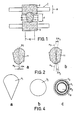
- Fig. 1 represents the situation in which the moulds are correctly aligned relative to each other and the lens 11 thus manufactured has the desired shape. If the moulds are not correctly aligned the lens 11 may adopt the shape represented in Fig. 2a.
- the axis of the mould 2 is designated a 2 and that of the mould 3 is designated a3.
- the incorrect shape of the lens 11 in Fig. 2a is caused by the fact that during moulding the axes of the moulds were shifted by A a as is indicated in Fig. 2a.
- a different incorrect lens shape is obtained if the axes of the moulds are tilted, as is represented in Fig. 2b by the angles Aa 2 and Aa 3 .
- an error may occur in the spacing d between the moulds.
- the said errors may be detected and corrected, as proposed by the present invention, by passing a radiation beam through the moulding device 1 and the material contained in said device and by determining the intensity distribution within the radiation spot formed by this radiation beam and comparing it with a reference.
- a radiation beam through the moulding device 1 and the material contained in said device and by determining the intensity distribution within the radiation spot formed by this radiation beam and comparing it with a reference.
- moulds which are transparent to the radiation of the alignment beam. Suitable moulds are for example those described in the previous Netherlands Patent Applications no.8003508 (PHN 9753) and no. 8100603 (PHN 9956).
- Figure 3 represents a first embodiment of a device in accordance with the invention.
- the device comprises a first radiation source 13, which emits an ultraviolet beam 12 for curing the photopolymerizable substance 10.
- a second radiation source 16 for example a HeNe laser, emits a second beam 17 by means of which the moulds 2 and 3 can be aligned.
- a prism 18 with a dichroic layer 19 which reflects the beam 12 almost completely and which transmits the beam 17 substantially without attenuation.
- the alignment beam 17 traverses the two moulds 2 and 3 and the transparent material 10 and is focussed by a lens 20 to form a radiation spot V.
- This radiation spot may be formed on the matt side 22 of a ground-glass screen 21, whose other side 63 is smooth and can be observed by means of a viewing device 64.
- a viewing device 64 instead of a ground-glass screen and a viewing device it is possible to employ a television camera-tube and monitor for observing the radiation spot V.
- the intensity distribution within the radiation spot depends on the distance (A a in Fig. 2a) between the axes of the moulds, the oblique position (Aa 2 and Aa 3 in Fig. 2b) of the moulds, and the spacing (d) between the moulds.
- Figure 4a, 4b and 4c show examples of different shapes the radiation spot V may have.
- a comma-like spot as represented by V 1 in Fig. 4a is formed if, for example, the axes of the moulds are shifted relative to each other.
- the moulds 2 and 3 may be shifted and/or tilted until the radiation spot assumes the shape V 2 shown in Fig. 4b.
- the axes of the moulds are then correctly aligned and the moulds are not tilted; however, the spacing between the moulds may then still differ from the desired value.
- Such a difference manifests itself as an error in the intensity distribution within the circular radiation spot.
- the intensity distribution may be detected visually or by means of a radiation-sensitive detection system and may be compared with a reference distribution. For example by moving the mould 2 in the direction of the arrow 8 the actual intensity distribution can be made identical to the desired distribution.
- the radiation spot a so-called Airy-spot, comprises a bright central portion CS and a plurality of concentric rings R 1 , R 2 .... of decreasing intensity.
- Fig. 5 represents an automated version of a device in accordance with the invention.
- a beam 17 which has passed through the moulding device and the material to be moulded is made to interfere with a reference beam 23.
- This beam is obtained by splitting the beam emitted by the source 16 by means of a beam-splitter prism 22.
- the reflection prisms 24 and 25 divert the reference beam around the moulding device and the splitter prism 26 ensures that a part of the reference beam is combined with the beam 17 emerging from the moulding device.
- the auxiliary lens 27 adapts the cross-section of the beam 17 to that of the beam 23.
- a radiation-sensitive detection system 28 is arranged at the location of the interference pattern formed by the beams 17 and 23 .
- Fig. 6 is a front view of this detection system. It comprises a multitude of spaced detectors 29, for example photo-diodes.
- the intensity distribution at the location of the detection system 28 is designated I in Fig. 6.
- the intensity distribution I comprises a steep central peak P and a plurality of side-lobes L 1 , L 2 , ... of lower intensity which decreases towards the outside, whilst the pattern I is disposed symmetrically relative to the detection system.
- the intensity distribution differs from the circularly symmetrical distribution represented by Fig. 6. If the moulds are correctly aligned but the spacing d between the moulds is not correct, the central peak P of the pattern I will be smaller and the side-lobes L 1 , Lz, ... will be larger compared with the situation represented in Fig. 6.
- the individual outputs of the detectors 29 are connected to separate inputs of an electronic device 30, which inter alia comprises a memory 31 and a comparator circuit 32.
- an electronic device 30 which inter alia comprises a memory 31 and a comparator circuit 32.
- the output signal of each of the detectors 29 is compared with one of a plurality of reference values stored in the memory 31.
- the result of this comparison is processed to form a control signal S c which is applied to devices for positioning one of the moulds or both moulds in the directions represented by the arrows 8, 8' and 21 in Fig. 5.
- the positioning devices lie outside the scope of the present invention and are only represented schematically by the block 33.
- optical elements by means of polymerizable materials it is not necessary, as already stated, that the entire element should consist of such a material, but use may be made of a glass preform, for example a lens.
- a comparatively thin layer of a polymerizable liquid may be applied to one or both surfaces of this lens.
- Such a method has the advantage that a lens is provided which for the greater part consists of a material having good optical properties, whilst the stringent requirements as regards the shape and surface quality of the lens surfaces can be met without an expensive finishing operation, such as polishing.
- An example of an element that can be manufactured with advantage using the said method is a so-called meniscus lens.
- Such a lens is difficult to manufacture using conventional techniques owing to the stringent requirements imposed on dimensional accuracy and thickness.
- both lens surfaces should be concentric relative to a point on the optical axis.
- Fig. 7 schematically represents a device for forming a meniscus lens. Again the alignment beam is designated 17 and the radiation beam used for polymerization is designated 12. An optical shutter by means of which the beam 12 can be interrupted is designated 35.
- the moulding device comprises one glass mould 41.
- the photo-polymerizable liquid 39 is applied between this mould and a glass lens preform 37 which is retained by means of a fixture 36.
- the surface 38 of the lens 37 has a centre of curvature 43 and a radius of curvature R 1 .
- the second surface of the lens (37, 39) to be formed, which surface coincides with the surface 40 of the mould 41, has a radius of curvature R z .
- an alignment beam 17, for example a He-Ne laser-beam is passed through the lens 37, the polymerizable liquid 39 and the mould 41, and the radiation spot formed by this beam is detected.
- Detection may be effected automatically, as described with reference to Fig. 5, or may be effected by visual observation using a ground-glass screen and a viewing device as shown in Fig. 7.
- the mould can be positioned correctly using positioning means, not shown, by a displacement in one or more of the directions X, Y and Z and/or tilting about the angles 8 and cp.
- the rear surface 42 of the mould may be curved, whilst the centre of curvature of the surface 42 may coincide with the centre 43.
- the refractive index n, of the lens 37 is, for example, equal to the refractive index of the photo-polymerizable material 39.
- the refractive index n 2 of the mould 41 differs from n" so that an image can be formed.
- the invention has been described with respect to the manufacture of a single lens, such as an aspherical lens, a cylindrical lens, a meniscus lens or a fresnel lens, but may also be used for the manufacture of a lens system, such as a so-called triplet.
- a lens system such as a so-called triplet.
- a lens preform 50 as shown in Fig. 8.
- a layer 51 or 52 respectively of a polymerizable liquid may be applied to both surfaces of this lens. After alignment the liquid is allowed to cure, so that the outermost lenses of the triplet are formed.
- the invention may also be used for the manufacture of other lens systems, such as a combination of spherical or aspherical lenses and a cylindrical lens or a combination of a fresnel lens with other lens types.
- the device may also be used for the manufacture of other optical elements, such as a prism or a diffraction grating.
- Fig. 9 is a front view of such a diffraction grating 53.
- One of the moulds in the moulding device in which the grating is formed has a pattern which is the complement of the grating pattern to be formed. Before the grating is formed definitively, the position of the mould carrying the grating pattern may be checked by observing the diffraction pattern of the beam which emerges from the moulding device.
Landscapes
- Engineering & Computer Science (AREA)
- Mechanical Engineering (AREA)
- Manufacturing & Machinery (AREA)
- General Physics & Mathematics (AREA)
- Ophthalmology & Optometry (AREA)
- Chemical & Material Sciences (AREA)
- Physics & Mathematics (AREA)
- Health & Medical Sciences (AREA)
- Materials Engineering (AREA)
- Organic Chemistry (AREA)
- Casting Or Compression Moulding Of Plastics Or The Like (AREA)
- Moulds For Moulding Plastics Or The Like (AREA)
- Heating, Cooling, Or Curing Plastics Or The Like In General (AREA)
- Processing And Handling Of Plastics And Other Materials For Molding In General (AREA)
- Footwear And Its Accessory, Manufacturing Method And Apparatuses (AREA)
Priority Applications (1)
| Application Number | Priority Date | Filing Date | Title |
|---|---|---|---|
| AT83200141T ATE21970T1 (de) | 1982-02-18 | 1983-01-27 | Verfahren und vorrichtung zum formen eines transparenten gegenstandes. |
Applications Claiming Priority (2)
| Application Number | Priority Date | Filing Date | Title |
|---|---|---|---|
| NL8200634A NL8200634A (nl) | 1982-02-18 | 1982-02-18 | Werkwijze en inrichting voor het vormen van een doorzichtig voorwerp. |
| NL8200634 | 1982-02-18 |
Publications (2)
| Publication Number | Publication Date |
|---|---|
| EP0087179A1 EP0087179A1 (en) | 1983-08-31 |
| EP0087179B1 true EP0087179B1 (en) | 1986-09-03 |
Family
ID=19839275
Family Applications (1)
| Application Number | Title | Priority Date | Filing Date |
|---|---|---|---|
| EP83200141A Expired EP0087179B1 (en) | 1982-02-18 | 1983-01-27 | Method and device for moulding a transparent object |
Country Status (7)
| Country | Link |
|---|---|
| US (1) | US4440699A (https=) |
| EP (1) | EP0087179B1 (https=) |
| JP (1) | JPS58151221A (https=) |
| AT (1) | ATE21970T1 (https=) |
| CA (1) | CA1193813A (https=) |
| DE (1) | DE3365756D1 (https=) |
| NL (1) | NL8200634A (https=) |
Families Citing this family (69)
| Publication number | Priority date | Publication date | Assignee | Title |
|---|---|---|---|---|
| EP0138763B1 (en) * | 1983-10-04 | 1989-01-18 | IntraCel Corporation | Process for moulding gels usable for thin layers electrophoresis |
| GB2155388A (en) * | 1984-03-09 | 1985-09-25 | Philips Electronic Associated | Moulding an accurately centred lens surface |
| DE3430439A1 (de) * | 1984-08-18 | 1986-05-07 | Hoechst Ag, 6230 Frankfurt | Verfahren und anordnung zur steuerung von verfahrensparametern bei der herstellung verstreckter folien |
| GB8507007D0 (en) * | 1985-03-19 | 1985-04-24 | Coopervision Optics | Casting lenses |
| US5158720A (en) * | 1985-12-09 | 1992-10-27 | Mcdonnell Douglas Corporation | Method and system for continuous in situ monitoring of viscosity |
| JPS62144914A (ja) * | 1985-12-18 | 1987-06-29 | Alps Electric Co Ltd | 光学部品の成型装置 |
| US5415816A (en) | 1986-01-28 | 1995-05-16 | Q2100, Inc. | Method for the production of plastic lenses |
| US6201037B1 (en) | 1986-01-28 | 2001-03-13 | Ophthalmic Research Group International, Inc. | Plastic lens composition and method for the production thereof |
| US5529728A (en) | 1986-01-28 | 1996-06-25 | Q2100, Inc. | Process for lens curing and coating |
| US6730244B1 (en) | 1986-01-28 | 2004-05-04 | Q2100, Inc. | Plastic lens and method for the production thereof |
| US5364256A (en) | 1986-01-28 | 1994-11-15 | Ophthalmic Research Group International, Inc. | Apparatus for the production of plastic lenses |
| JPH0243590A (ja) * | 1988-08-03 | 1990-02-14 | Sharp Corp | ブレーズホログラムの製造方法 |
| JPH04161305A (ja) * | 1990-10-26 | 1992-06-04 | Canon Inc | レンズの製造方法及び製造装置 |
| NL9002517A (nl) * | 1990-11-19 | 1992-06-16 | Philips Nv | Werkwijze voor het vervaardigen van een optisch uitleesbare plaat, alsmede inrichting voor de uitvoering van de werkwijze. |
| TW325744U (en) * | 1993-07-21 | 1998-01-21 | Ciba Geigy Ag | Two-sided contact lens mold |
| EP0756361B1 (en) * | 1995-07-21 | 1997-06-25 | Hewlett-Packard GmbH | Method and arrangement for adjusting a mirror to a laser resonator |
| US6022498A (en) | 1996-04-19 | 2000-02-08 | Q2100, Inc. | Methods for eyeglass lens curing using ultraviolet light |
| US6280171B1 (en) | 1996-06-14 | 2001-08-28 | Q2100, Inc. | El apparatus for eyeglass lens curing using ultraviolet light |
| DE19631736A1 (de) * | 1996-08-06 | 1998-02-12 | Stm Sensor Technologie Muenche | Verfahren und Vorrichtung zum Herstellen von Linsen mikrooptischer Systeme sowie Lichtsender/Lichtempfängersystem |
| US5989462A (en) * | 1997-07-31 | 1999-11-23 | Q2100, Inc. | Method and composition for producing ultraviolent blocking lenses |
| JPH11170275A (ja) * | 1997-12-17 | 1999-06-29 | Topcon Corp | レンズ成形装置及びレンズ成形器具 |
| US6451226B1 (en) | 1998-09-25 | 2002-09-17 | Q2100, Inc. | Plastic lens compositions |
| US6419873B1 (en) * | 1999-03-19 | 2002-07-16 | Q2100, Inc. | Plastic lens systems, compositions, and methods |
| GB0002091D0 (en) * | 2000-01-28 | 2000-03-22 | Aspect Vision Care Ltd | Toric lens manufacture |
| US6960312B2 (en) | 2000-03-30 | 2005-11-01 | Q2100, Inc. | Methods for the production of plastic lenses |
| US6723260B1 (en) | 2000-03-30 | 2004-04-20 | Q2100, Inc. | Method for marking a plastic eyeglass lens using a mold assembly holder |
| US6698708B1 (en) | 2000-03-30 | 2004-03-02 | Q2100, Inc. | Gasket and mold assembly for producing plastic lenses |
| US6716375B1 (en) | 2000-03-30 | 2004-04-06 | Q2100, Inc. | Apparatus and method for heating a polymerizable composition |
| US6632535B1 (en) | 2000-06-08 | 2003-10-14 | Q2100, Inc. | Method of forming antireflective coatings |
| US6752613B2 (en) | 2001-02-20 | 2004-06-22 | Q2100, Inc. | Apparatus for preparing an eyeglass lens having a controller for initiation of lens curing |
| US6790022B1 (en) | 2001-02-20 | 2004-09-14 | Q2100, Inc. | Apparatus for preparing an eyeglass lens having a movable lamp mount |
| US6893245B2 (en) | 2001-02-20 | 2005-05-17 | Q2100, Inc. | Apparatus for preparing an eyeglass lens having a computer system controller |
| US7025910B2 (en) | 2001-02-20 | 2006-04-11 | Q2100, Inc | Method of entering prescription information |
| US7060208B2 (en) | 2001-02-20 | 2006-06-13 | Q2100, Inc. | Method of preparing an eyeglass lens with a controller |
| US6808381B2 (en) | 2001-02-20 | 2004-10-26 | Q2100, Inc. | Apparatus for preparing an eyeglass lens having a controller |
| US6712331B2 (en) | 2001-02-20 | 2004-03-30 | Q2100, Inc. | Holder for mold assemblies with indicia |
| US7051290B2 (en) * | 2001-02-20 | 2006-05-23 | Q2100, Inc. | Graphical interface for receiving eyeglass prescription information |
| US6840752B2 (en) * | 2001-02-20 | 2005-01-11 | Q2100, Inc. | Apparatus for preparing multiple eyeglass lenses |
| US6875005B2 (en) | 2001-02-20 | 2005-04-05 | Q1200, Inc. | Apparatus for preparing an eyeglass lens having a gating device |
| US6790024B2 (en) | 2001-02-20 | 2004-09-14 | Q2100, Inc. | Apparatus for preparing an eyeglass lens having multiple conveyor systems |
| US7037449B2 (en) | 2001-02-20 | 2006-05-02 | Q2100, Inc. | Method for automatically shutting down a lens forming apparatus |
| US7083404B2 (en) * | 2001-02-20 | 2006-08-01 | Q2100, Inc. | System for preparing an eyeglass lens using a mold holder |
| US6899831B1 (en) | 2001-02-20 | 2005-05-31 | Q2100, Inc. | Method of preparing an eyeglass lens by delayed entry of mold assemblies into a curing apparatus |
| US7004740B2 (en) | 2001-02-20 | 2006-02-28 | Q2100, Inc. | Apparatus for preparing an eyeglass lens having a heating system |
| US6709257B2 (en) | 2001-02-20 | 2004-03-23 | Q2100, Inc. | Eyeglass lens forming apparatus with sensor |
| US6676398B2 (en) | 2001-02-20 | 2004-01-13 | Q2100, Inc. | Apparatus for preparing an eyeglass lens having a prescription reader |
| US7124995B2 (en) * | 2001-02-20 | 2006-10-24 | Q2100, Inc. | Holder for mold assemblies and molds |
| US6863518B2 (en) | 2001-02-20 | 2005-03-08 | Q2100, Inc. | Mold filing apparatus having multiple fill stations |
| US6655946B2 (en) | 2001-02-20 | 2003-12-02 | Q2100, Inc. | Apparatus for preparing an eyeglass lens having a controller for conveyor and curing units |
| US7139636B2 (en) * | 2001-02-20 | 2006-11-21 | Q2100, Inc. | System for preparing eyeglass lenses with bar code reader |
| US6962669B2 (en) | 2001-02-20 | 2005-11-08 | Q2100, Inc. | Computerized controller for an eyeglass lens curing apparatus |
| US7011773B2 (en) | 2001-02-20 | 2006-03-14 | Q2100, Inc. | Graphical interface to display mold assembly position in a lens forming apparatus |
| US6702564B2 (en) | 2001-02-20 | 2004-03-09 | Q2100, Inc. | System for preparing an eyeglass lens using colored mold holders |
| US6758663B2 (en) | 2001-02-20 | 2004-07-06 | Q2100, Inc. | System for preparing eyeglass lenses with a high volume curing unit |
| US7052262B2 (en) | 2001-02-20 | 2006-05-30 | Q2100, Inc. | System for preparing eyeglasses lens with filling station |
| US6612828B2 (en) | 2001-02-20 | 2003-09-02 | Q2100, Inc. | Fill system with controller for monitoring use |
| US7074352B2 (en) | 2001-02-20 | 2006-07-11 | Q2100, Inc. | Graphical interface for monitoring usage of components of a lens forming apparatus |
| US6726463B2 (en) | 2001-02-20 | 2004-04-27 | Q2100, Inc. | Apparatus for preparing an eyeglass lens having a dual computer system controller |
| US6676399B1 (en) | 2001-02-20 | 2004-01-13 | Q2100, Inc. | Apparatus for preparing an eyeglass lens having sensors for tracking mold assemblies |
| US7045081B2 (en) | 2001-02-20 | 2006-05-16 | Q2100, Inc. | Method of monitoring components of a lens forming apparatus |
| SE0101702D0 (sv) * | 2001-05-15 | 2001-05-15 | Ardenia Investments Ltd | Novel potentiating compounds |
| US7044429B1 (en) | 2002-03-15 | 2006-05-16 | Q2100, Inc. | Methods and systems for coating eyeglass lens molds |
| US6464484B1 (en) | 2002-03-30 | 2002-10-15 | Q2100, Inc. | Apparatus and system for the production of plastic lenses |
| JP2005119940A (ja) * | 2003-09-26 | 2005-05-12 | Nippon Sheet Glass Co Ltd | エッチング加工物品およびそれを用いた成形構造体並びにそれらの製造方法 |
| EP2067613A1 (en) * | 2007-12-06 | 2009-06-10 | Essilor International, Cie Generale D'opitque | Method and device for manufacturing an opthalmic lens using a photoactive material |
| ATE500956T1 (de) * | 2007-12-06 | 2011-03-15 | Essilor Int | Verfahren und vorrichtung zur herstellung einer ophthalmischen linse mit fotoaktivem material |
| JPWO2010087082A1 (ja) * | 2009-01-30 | 2012-07-26 | コニカミノルタアドバンストレイヤー株式会社 | ウエハレンズ製造装置及びウエハレンズの製造方法 |
| US10969560B2 (en) | 2017-05-04 | 2021-04-06 | Lightpath Technologies, Inc. | Integrated optical assembly and manufacturing the same |
| DE102018112436A1 (de) * | 2018-05-24 | 2019-11-28 | Carl Zeiss Jena Gmbh | Verfahren und Vorrichtungen zur Bestimmung von Ausrichtungsfehlern von Strahlquellen und für deren Korrektur |
Family Cites Families (12)
| Publication number | Priority date | Publication date | Assignee | Title |
|---|---|---|---|---|
| US2332674A (en) * | 1940-08-12 | 1943-10-26 | Univis Lens Co | Method of and means for forming unbreakable lenses |
| GB1040889A (en) * | 1962-07-11 | 1966-09-01 | Pilkington Brothers Ltd | Improvements in or relating to the moulding of glass articles |
| US3244497A (en) * | 1962-09-27 | 1966-04-05 | Bausch & Lomb | Glass press mold structure with temperature regulation |
| US3454686A (en) * | 1964-10-29 | 1969-07-08 | Harry S Jones | Method of shaping an aspheric lens |
| US4113224A (en) * | 1975-04-08 | 1978-09-12 | Bausch & Lomb Incorporated | Apparatus for forming optical lenses |
| US4037969A (en) * | 1976-04-02 | 1977-07-26 | Bell Telephone Laboratories, Incorporated | Zone plate alignment marks |
| US4166088A (en) * | 1977-05-25 | 1979-08-28 | Neefe Charles W | Method of making high quality plastic lenses |
| FR2436967A1 (fr) * | 1978-09-19 | 1980-04-18 | Thomson Csf | Procede d'alignement optique de motifs dans deux plans rapproches et dispositif d'alignement mettant en oeuvre un tel procede |
| FR2469727A1 (fr) * | 1979-11-16 | 1981-05-22 | Thomson Csf | Procede de centrage automatique d'une fibre optique dans un revetement de protection primaire, et dispositif utilise pour la mise en oeuvre de ce procede |
| IT1119599B (it) * | 1979-12-07 | 1986-03-10 | Cselt Centro Studi Lab Telecom | Procedimento per la sagomatura sferica delle terminazioni delle fibre ottiche |
| US4298887A (en) * | 1980-06-09 | 1981-11-03 | Rockwell International Corporation | Non-uniformity correction in a multielement detector array |
| US4363827A (en) * | 1981-02-23 | 1982-12-14 | Bell Telephone Laboratories, Incorporated | Manufacture of concentric coatings for fiber waveguides |
-
1982
- 1982-02-18 NL NL8200634A patent/NL8200634A/nl not_active Application Discontinuation
- 1982-05-24 US US06/381,114 patent/US4440699A/en not_active Expired - Fee Related
-
1983
- 1983-01-27 AT AT83200141T patent/ATE21970T1/de not_active IP Right Cessation
- 1983-01-27 DE DE8383200141T patent/DE3365756D1/de not_active Expired
- 1983-01-27 EP EP83200141A patent/EP0087179B1/en not_active Expired
- 1983-02-15 JP JP58022242A patent/JPS58151221A/ja active Granted
- 1983-02-17 CA CA000421851A patent/CA1193813A/en not_active Expired
Also Published As
| Publication number | Publication date |
|---|---|
| CA1193813A (en) | 1985-09-24 |
| JPH024415B2 (https=) | 1990-01-29 |
| NL8200634A (nl) | 1983-09-16 |
| ATE21970T1 (de) | 1986-09-15 |
| EP0087179A1 (en) | 1983-08-31 |
| JPS58151221A (ja) | 1983-09-08 |
| US4440699A (en) | 1984-04-03 |
| DE3365756D1 (en) | 1986-10-09 |
Similar Documents
| Publication | Publication Date | Title |
|---|---|---|
| EP0087179B1 (en) | Method and device for moulding a transparent object | |
| CA1263747A (en) | Optical scanning unit with a translational- position and angular-position detection system | |
| US5601758A (en) | Method for fabricating a lens/mirror tower | |
| KR900006954B1 (ko) | 광학헤드장치 | |
| USRE32988E (en) | Single collimator lens having one aspherical surface | |
| EP0179531B1 (en) | Single bi-aspherical lens | |
| EP0127448B1 (en) | Focussing error detecting apparatus | |
| US4537473A (en) | Fiducial surfaces | |
| JPS60103308A (ja) | マイクロフレネルレンズの製造方法 | |
| US4468122A (en) | Interferometer for checking the shape of convex surfaces of optical components | |
| US4501493A (en) | Apparatus for detecting a position of an optical pickup | |
| IT8223619A1 (it) | Prisma per la suddivisione di un fascio, metodo di fabbricazione dello stesso ed unita' ottica di lettura e/o di scrittura dotata di tale prisma | |
| US5067800A (en) | Composite optical article and method of manufacture thereof | |
| CA1333848C (en) | Device for performing measurements on a transparent object, method of manufacturing a fibre and fibre manufactured by means of said method | |
| US5535058A (en) | Focus error detecting element and optical head using the same | |
| US5176731A (en) | Device for performing measurements on a transparent object, method of manufacturing a fiber and fiber manufactured by means of said method | |
| US20220283448A1 (en) | Polarized lens for spectacles, method for manufacturing polarized lens for spectacles, method for manufacturing framed spectacle, and method for inspecting polarized lens for spectacles | |
| Howden et al. | Refracting replica aspheric optics | |
| JPS5973712A (ja) | 平面度測定装置 | |
| GB2129931A (en) | Apparatus for detecting position of optical pick-up | |
| JPS6153602A (ja) | 光学部材 | |
| JP7418100B2 (ja) | 光学素子及び光学素子の製造方法 | |
| JPH0373055B2 (https=) | ||
| JPS60103309A (ja) | マイクロフレネルレンズの製造方法 | |
| JPS63280207A (ja) | 焦点検出装置 |
Legal Events
| Date | Code | Title | Description |
|---|---|---|---|
| PUAI | Public reference made under article 153(3) epc to a published international application that has entered the european phase |
Free format text: ORIGINAL CODE: 0009012 |
|
| AK | Designated contracting states |
Designated state(s): AT DE FR GB IT NL |
|
| 17P | Request for examination filed |
Effective date: 19831011 |
|
| GRAA | (expected) grant |
Free format text: ORIGINAL CODE: 0009210 |
|
| AK | Designated contracting states |
Kind code of ref document: B1 Designated state(s): AT DE FR GB IT NL |
|
| REF | Corresponds to: |
Ref document number: 21970 Country of ref document: AT Date of ref document: 19860915 Kind code of ref document: T |
|
| ITF | It: translation for a ep patent filed | ||
| REF | Corresponds to: |
Ref document number: 3365756 Country of ref document: DE Date of ref document: 19861009 |
|
| ET | Fr: translation filed | ||
| PGFP | Annual fee paid to national office [announced via postgrant information from national office to epo] |
Ref country code: AT Payment date: 19870113 Year of fee payment: 5 |
|
| PGFP | Annual fee paid to national office [announced via postgrant information from national office to epo] |
Ref country code: NL Payment date: 19870131 Year of fee payment: 5 |
|
| PLBE | No opposition filed within time limit |
Free format text: ORIGINAL CODE: 0009261 |
|
| STAA | Information on the status of an ep patent application or granted ep patent |
Free format text: STATUS: NO OPPOSITION FILED WITHIN TIME LIMIT |
|
| 26N | No opposition filed | ||
| PG25 | Lapsed in a contracting state [announced via postgrant information from national office to epo] |
Ref country code: AT Effective date: 19890127 |
|
| PG25 | Lapsed in a contracting state [announced via postgrant information from national office to epo] |
Ref country code: NL Effective date: 19890801 |
|
| NLV4 | Nl: lapsed or anulled due to non-payment of the annual fee | ||
| PGFP | Annual fee paid to national office [announced via postgrant information from national office to epo] |
Ref country code: GB Payment date: 19901221 Year of fee payment: 9 |
|
| PGFP | Annual fee paid to national office [announced via postgrant information from national office to epo] |
Ref country code: FR Payment date: 19910118 Year of fee payment: 9 |
|
| ITTA | It: last paid annual fee | ||
| PGFP | Annual fee paid to national office [announced via postgrant information from national office to epo] |
Ref country code: DE Payment date: 19910322 Year of fee payment: 9 |
|
| PG25 | Lapsed in a contracting state [announced via postgrant information from national office to epo] |
Ref country code: GB Effective date: 19920127 |
|
| GBPC | Gb: european patent ceased through non-payment of renewal fee | ||
| PG25 | Lapsed in a contracting state [announced via postgrant information from national office to epo] |
Ref country code: FR Effective date: 19920930 |
|
| PG25 | Lapsed in a contracting state [announced via postgrant information from national office to epo] |
Ref country code: DE Effective date: 19921001 |
|
| REG | Reference to a national code |
Ref country code: FR Ref legal event code: ST |