EP0087114B1 - Videobandaufzeichnungsgerät - Google Patents
Videobandaufzeichnungsgerät Download PDFInfo
- Publication number
- EP0087114B1 EP0087114B1 EP83101457A EP83101457A EP0087114B1 EP 0087114 B1 EP0087114 B1 EP 0087114B1 EP 83101457 A EP83101457 A EP 83101457A EP 83101457 A EP83101457 A EP 83101457A EP 0087114 B1 EP0087114 B1 EP 0087114B1
- Authority
- EP
- European Patent Office
- Prior art keywords
- tape
- video
- audio
- heads
- cylinder
- Prior art date
- Legal status (The legal status is an assumption and is not a legal conclusion. Google has not performed a legal analysis and makes no representation as to the accuracy of the status listed.)
- Expired - Lifetime
Links
- 230000005236 sound signal Effects 0.000 claims description 54
- 238000006243 chemical reaction Methods 0.000 claims description 3
- 230000005415 magnetization Effects 0.000 description 4
- 230000002238 attenuated effect Effects 0.000 description 3
- 230000003247 decreasing effect Effects 0.000 description 1
- 230000001419 dependent effect Effects 0.000 description 1
- 238000010586 diagram Methods 0.000 description 1
- 230000007774 longterm Effects 0.000 description 1
- 238000012856 packing Methods 0.000 description 1
- 230000001360 synchronised effect Effects 0.000 description 1
Images
Classifications
-
- H—ELECTRICITY
- H04—ELECTRIC COMMUNICATION TECHNIQUE
- H04N—PICTORIAL COMMUNICATION, e.g. TELEVISION
- H04N5/00—Details of television systems
- H04N5/76—Television signal recording
-
- G—PHYSICS
- G11—INFORMATION STORAGE
- G11B—INFORMATION STORAGE BASED ON RELATIVE MOVEMENT BETWEEN RECORD CARRIER AND TRANSDUCER
- G11B5/00—Recording by magnetisation or demagnetisation of a record carrier; Reproducing by magnetic means; Record carriers therefor
- G11B5/008—Recording on, or reproducing or erasing from, magnetic tapes, sheets, e.g. cards, or wires
- G11B5/00813—Recording on, or reproducing or erasing from, magnetic tapes, sheets, e.g. cards, or wires magnetic tapes
- G11B5/00847—Recording on, or reproducing or erasing from, magnetic tapes, sheets, e.g. cards, or wires magnetic tapes on transverse tracks
- G11B5/0086—Recording on, or reproducing or erasing from, magnetic tapes, sheets, e.g. cards, or wires magnetic tapes on transverse tracks using cyclically driven heads providing segmented tracks
-
- G—PHYSICS
- G11—INFORMATION STORAGE
- G11B—INFORMATION STORAGE BASED ON RELATIVE MOVEMENT BETWEEN RECORD CARRIER AND TRANSDUCER
- G11B15/00—Driving, starting or stopping record carriers of filamentary or web form; Driving both such record carriers and heads; Guiding such record carriers or containers therefor; Control thereof; Control of operating function
- G11B15/02—Control of operating function, e.g. switching from recording to reproducing
-
- G—PHYSICS
- G11—INFORMATION STORAGE
- G11B—INFORMATION STORAGE BASED ON RELATIVE MOVEMENT BETWEEN RECORD CARRIER AND TRANSDUCER
- G11B5/00—Recording by magnetisation or demagnetisation of a record carrier; Reproducing by magnetic means; Record carriers therefor
- G11B5/008—Recording on, or reproducing or erasing from, magnetic tapes, sheets, e.g. cards, or wires
- G11B5/00813—Recording on, or reproducing or erasing from, magnetic tapes, sheets, e.g. cards, or wires magnetic tapes
- G11B5/00878—Recording on, or reproducing or erasing from, magnetic tapes, sheets, e.g. cards, or wires magnetic tapes transducing different track configurations or formats on the same tape
-
- G—PHYSICS
- G11—INFORMATION STORAGE
- G11B—INFORMATION STORAGE BASED ON RELATIVE MOVEMENT BETWEEN RECORD CARRIER AND TRANSDUCER
- G11B5/00—Recording by magnetisation or demagnetisation of a record carrier; Reproducing by magnetic means; Record carriers therefor
- G11B5/48—Disposition or mounting of heads or head supports relative to record carriers ; arrangements of heads, e.g. for scanning the record carrier to increase the relative speed
- G11B5/52—Disposition or mounting of heads or head supports relative to record carriers ; arrangements of heads, e.g. for scanning the record carrier to increase the relative speed with simultaneous movement of head and record carrier, e.g. rotation of head
- G11B5/53—Disposition or mounting of heads on rotating support
- G11B5/531—Disposition of more than one recording or reproducing head on support rotating cyclically around an axis
- G11B5/534—Disposition of more than one recording or reproducing head on support rotating cyclically around an axis inclined relative to the direction of movement of the tape, e.g. for helicoidal scanning
-
- H—ELECTRICITY
- H04—ELECTRIC COMMUNICATION TECHNIQUE
- H04N—PICTORIAL COMMUNICATION, e.g. TELEVISION
- H04N5/00—Details of television systems
- H04N5/76—Television signal recording
- H04N5/78—Television signal recording using magnetic recording
- H04N5/782—Television signal recording using magnetic recording on tape
- H04N5/7824—Television signal recording using magnetic recording on tape with rotating magnetic heads
- H04N5/7826—Television signal recording using magnetic recording on tape with rotating magnetic heads involving helical scanning of the magnetic tape
-
- H—ELECTRICITY
- H04—ELECTRIC COMMUNICATION TECHNIQUE
- H04N—PICTORIAL COMMUNICATION, e.g. TELEVISION
- H04N9/00—Details of colour television systems
- H04N9/79—Processing of colour television signals in connection with recording
- H04N9/7921—Processing of colour television signals in connection with recording for more than one processing mode
-
- H—ELECTRICITY
- H04—ELECTRIC COMMUNICATION TECHNIQUE
- H04N—PICTORIAL COMMUNICATION, e.g. TELEVISION
- H04N9/00—Details of colour television systems
- H04N9/79—Processing of colour television signals in connection with recording
- H04N9/80—Transformation of the television signal for recording, e.g. modulation, frequency changing; Inverse transformation for playback
- H04N9/802—Transformation of the television signal for recording, e.g. modulation, frequency changing; Inverse transformation for playback involving processing of the sound signal
-
- H—ELECTRICITY
- H04—ELECTRIC COMMUNICATION TECHNIQUE
- H04N—PICTORIAL COMMUNICATION, e.g. TELEVISION
- H04N9/00—Details of colour television systems
- H04N9/79—Processing of colour television signals in connection with recording
- H04N9/80—Transformation of the television signal for recording, e.g. modulation, frequency changing; Inverse transformation for playback
- H04N9/82—Transformation of the television signal for recording, e.g. modulation, frequency changing; Inverse transformation for playback the individual colour picture signal components being recorded simultaneously only
- H04N9/83—Transformation of the television signal for recording, e.g. modulation, frequency changing; Inverse transformation for playback the individual colour picture signal components being recorded simultaneously only the recorded chrominance signal occupying a frequency band under the frequency band of the recorded brightness signal
- H04N9/835—Transformation of the television signal for recording, e.g. modulation, frequency changing; Inverse transformation for playback the individual colour picture signal components being recorded simultaneously only the recorded chrominance signal occupying a frequency band under the frequency band of the recorded brightness signal involving processing of the sound signal
- H04N9/8355—Transformation of the television signal for recording, e.g. modulation, frequency changing; Inverse transformation for playback the individual colour picture signal components being recorded simultaneously only the recorded chrominance signal occupying a frequency band under the frequency band of the recorded brightness signal involving processing of the sound signal the sound carriers being frequency multiplexed between the luminance carrier and the chrominance carrier
Definitions
- the invention relates to a magnetic recording/ reproducing device comprising a rotatable cylinder, rotated by a driving means; a tape loading means for loading a magnetic tape such that a portion of said magnetic tape is helically wound on said rotatable cylinder for a predetermined angle; tape moving means for moving said tape at a predetermined speed; first and second video heads mounted opposite to each other on said rotatable cylinder for recording/reproducing video signal on said magnetic tape; first and second audio heads mounted opposite to each other on said rotatable cylinder between the video heads for recording/reproducing audio signal on said magnetic tape.
- Such a device is known from JP-A-5558807.
- a rotatable cylinder carries at least one video magnetic head.
- a magnetic tape is wound spirally around the cylinder by a predetermined angle.
- the video magnetic head sequentially records or reproduces a video signal as it scans diagonally across the magnetic tape.
- DE-A-19 35 109 provides a magnetic recording and/or reproducing device showing partial and complete overlapping of the tracks for two different signals, namely the luminance and chrominance signals. It is indicated that crosstalk between the overlapping tracks can be decreased by using different frequency ranges for the two signals, different gap widths and different azimuth angles of the head for these two signals. No information is being given about the recording of audio signals in an audio track.
- JP-A-5644285 relates to the recording of dynamic and still TV pictures.
- the audio signals are not separately recording on the recording medium (a disc), but are transferred into a frequency band between converted color signal components and FM luminance signal components.
- a magnetic recording/reproducing device as defined above is characterized in that said first and second video heads have a predetermined angle of azimuth of ⁇ 6° in opposite directions and said first and second audio heads have a predetermined angle of azimuth of ⁇ 30° inclined in opposite directions; that said tape moving means moves said tape at such a speed that said first and second audio heads obliquely traverse said tape to provide, respectively, first and second audio tracks overlapping with each other at their sides, and that said first and second video heads obliquely traverse said tape to provide, respectively, first and second video tracks which are overlapping with each other at their sides, and at the same time, are overlapping, respectively, completely with said first and second audio tracks; and that said audio signal is recorded in frequecy modulated form, the frequency of the carrier falling in a low side-band of a frequency modulated luminance signal portion of said video signal and adjacent to a low frequency conversion color signal portion of said video signal.
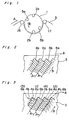
- Mounted in the cylinder 1 are video heads 2a and 2b and audio heads 5a and 5b, in which the angle of inclination of head gap (azimuth) is different from each other.
- the video heads 2a and 2b are spaced in 180° angular relation to each other and, also, the audio heads 5a and 5b are spaced in 180° angular relation to each other.
- the audio heads 5a and 5b are spaced in 60° angular relation from the video heads 2a and 2b, respectively.
- a pair of tape guides 16 and 17 are provided to move a magnetic tape 3 in a position for recording or playback. More specifically, the tape guides 16 and 17 move and guide the magnetic tape 3 around the cylinder surface for a degrees slightly greater than 180°. At the same time, the magnetic tape 3 is spirally wound on the cylinder surface with a predetermined inclination with respect to the axis of the cylinder, as in prior art video tape recordings of helical scan type.
- the magnetic tape 3 can be advanced either in a standard tape speed for standard recording or in a slow tape speed for high density, long term recording.
- the slow tape speed is 1/N times the standard speed, wherein N is an integer, preferably 3.
- tracks 4a and 4b on which a video signal is recorded under the slow tape speed operation are shown.
- the tracks 4a and 4b are formed on the magnetic tape 3 by the scan of the video heads 2a and 2b, respectively.
- the tracks 4a and 4b occur alternately with a pitch P, and are partly overlapping with each other. Since the head gap of the video head 2a has an azimuth of +6°, and the head gap of the video head 2b has an azimuth of -6°, the tracks 4a and 4b are magnetized, during the recording of the video signal, in directions which are inclined by +6° and -6°, respectively, with respect to the direction perpendicular to the head scanning direction B.
- the audio heads 5a and 5b scan diagonally on the running magnetic tape 3 during the recording or playback mode to record or reproduce the audio signal on the magnetic tape 3.
- the audio heads 5a and 5b are provided at a predetermined level on the cylinder surface (for example, they are provided on the cylinder at a level which is 47 micrometers above the level where the video heads 2a and 2b are provided) and each having a predetermined head width in relation to head width of the video heads (for example, when video heads 2a and 2b have a head width of 32 micrometers, the audio heads 5a and 5b have a head width of 30 micrometers).
- the audio heads 5a and 5b scan over tracks 6a and 6b which occupy almost the same area as that of the tracks 4a and 4b, respectively, as shown in Fig. 3, in which the tracks 6a and 6b are shown by broken lines. More particularly, the audio head 5a scans along a line diagonally across the magnetic tape 3 to form a track 6a for recording a frequency modulated audio signal and, then, at a different moment, the video head 2a scans along the same line to form a track 4a for recording a video signal.
- numbers each given in parentheses above the reference character show the order of tracking.
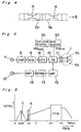
- the video tape recorder includes an amplifier 8 connected to an input terminal 7, a modulator 9 for effecting a frequency modulation by a carrier wave having 1.3 MHz, an attenuator 18 connected to the modulator 9 and coupled with a tape speed selector30, a switching circuit 10 connected to the attenuator 18 and coupled with a mode selector 32, and a rotary transformer 11 and connected to the switching circuit 10.
- a part of the rotary transformer 11 is provided in the cylinder 1 and is connected to audio heads 5a and 5b.
- the video tape recorder further includes an amplifier 12 connected to the switching circuit 10, a demodulator 13 connected to the amplifier 12, and an amplifier 14 connected to the demodulator 13, which amplifier 14 is in turn connected to an output terminal 15.
- the tape speed selector 30 controls the attenuator 18 such that when a standard tape speed is selected, the degree of attenuation effected by the attenuator 18 is increased by about 10 dB when compared with the degree of attenuation in the slow tape speed (1 ⁇ 2 of the standard tape speed). The reason for this will be described later.
- the mode selector 32 controls the switching circuit 10 such that when the recording mode is selected, the switching circuit 10 connects the attenuator 18 with transformer 11 and disconnects the amplifier 12 from the transformer 11, and at the saem time, the switching circuit 10 applies the audio signal on carrier alternately to the audio heads 5a and 5b in a synchronized relation with the rotation of the cylinder 1, and when the playback mode is selected, the switching circuit 10 connects the amplifier 12 with transformer 11 and disconnects the attenuator 18 from transformer 11, and at the same time, the switching circuit 10 receives the reproduced audio signal on carrier alternately from the audio heads 5a and 5b.
- an audio signal applied to an input terminal 7 is amplified by an amplifier 8 and, then, it is frequency-modulated in a modulator 9 on a carrier wave having 1.3 MHz.
- Th frequency-modulated audio signal, i.e., the audio signal on the carrier is then applied through attenuator 18, switching circuit 10 and transformer 11 to audio heads 5a and 5b for effecting the recording of audio signal on carrier on the tracks 6a and 6b in a manner shown in Fig. 3.
- Each of the audio heads 5a and 5b has a head gap G inclined in several tens of degrees (such as 30°) from a line perpendicular to the head scanning direction B. Furthermore, the direction of inclination of the head gap G in the audio head 5a is opposite to that in the audio head 5b and, therefore, the tracks 6a and 6b are magnetized, during the recording of the audio signal, in directions which are inclined, e.g., -30° and +30°, respectively, with respect to the direction perpendicular to the head scanning direction.
- the tracks 4a and 4b which occupy the same area as the tracks 6a and 6b, respectively, are magnetized with inclinations of +6° and -6°, as mentioned above, the direction of magnetization on the track 4a is inclined 36° with respect to the direction of magnetization on the track 6a. The same can be said to the magnetization on the tracks 4b and 6b.
- Such an inclination between the directions of magnetization on the tracks 4a and 6a, or 4b and 6b reduces undesirable interferences between signals on the tracks 4a and 6a, or 4b and 6b.
- the carrier current applied to the audio heads 5a and 5b during the recording mode is so controlled as to render the carrier-to-noise ratio of the carrier of the audio signal being 20 dB during the playback.
- the recorded audio signal on the carrier is reproduced alternately by the audio heads 5a and 5b, and is applied through the rotary transformer 11, switching circuit 10 to the amplifier 12, wherein it is amplified to a predetermined level. Then the amplified audio signal on the carrier is applied to the demodulator 13 which produces a demodulated audio signal.
- the demodulated audio signal is amplified by the amplifier 14, and is produced from the output terminal 15.
- the audio heads 5a and 5b will not pick up any video signal because of the following reasons.
- the first reason is that the video signal sensed by the audio heads is attenuated by the azimuth loss.
- the second reason is that the carrier for the audio signal has a frequency about 1.3 MHz, as shown in Fig. 6, which frequency is offset from the frequency band of the video signal, such as low frequency conversion color signal C having a frequency band of, e.g., 629 KHz ⁇ 500 KHz, and frequency modulated luminance signal Y(FM) havng a frequency band between 3.4 MHz and 4.4 MHz.
- the frequency band of the carrier for the audio signal falls in a high frequency component region of luminance signal of a low side-band of the frequency modulated luminance signal Y(FM), the amplitude of the low side-band in this region is rather low and, therefore, the video signal scarcely affects on the audio signal.
- the video heads 2a and 2b will not pick up any audio signal because of the azimuth loss of the audio signal, and of the attenuation of the audio signal effected when the video signal is recorded over the audio signal.
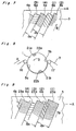
- the tape speed is an integer number, such as 3, times as fast as that in the slow tape speed operation and, therefore, the tracks 4a, 4b, 6a and 6b formed on the magnetic tape 3 are different from that obtained under the slow tape speed operation. More specifically, as shown in Fig. 7, the video heads 2a and 2b scan to form tracks 4a and 4b, respectively, and the audio heads 5a and 5b scan to form tracks 6a and 6b, respectively, with slight overlaps between tracks 4a and 6a and between 4b and 6b.
- the video and audio tracks in a pair are repeated with a pitch of 3P, and are formed in the order indicated by a number in parentheses above the reference character.
- the tape speed selector 30 increases the degree of attenuation in the attenuator 18 by about 10 dB in the standard tape speed recording mode when compared with that in the slow tape speed recording mode. In this manner, since the carrier current supplied to the audio heads 5a and 5b is reduced in the standard tape speed recording mode, the audio signal on carrier reproduced in the standard tape speed playback mode is about the same as that reproduced in the slow tape speed playback mode. Furthermore, by the above arrangement, although the video head 2a or 2b may pick up the audio signal in the standard or slow tape speed recording mode, the level of the sensed audio signal by the video head 2a or 2b is very low, and therefore, there will be no interference between the audio signal and video signal.
- the reproduced audio signal since the audio signal on carrier as recorded on the tracks 6a and 6b is a frequency-modulated signal, the reproduced audio signal has a high quality regardless of low recording level.
- the reproduced audio signal has S/N ratio above 55 dB and frequency characteristic between 20 Hz and 20 KHz, with wow flatter as less as 0.005%.
- a video tape recorder which comprises a pair of video heads 21 a and 21 b located at opposite ends of a first cylinder diameter position for use in recording and reproducing video signal under slow tape speed operation, and another pair of video heads 22a and 22b located at opposite ends of a second cylinder diameter portion, which is closely adjacent to the first cylinder diameter position, for use in recording and reproducing video signal under standard tape speed operation.
- Each of the video heads 21 a and 21 b has a head width of 32 micrometers, which is the same as that of the video heads 2a and 2b in the first embodiment, and each of the video heads 22a and 22b has a head width of 70 micrometers.
- the audio heads 5a and 5b have 30 micrometers head width as in the previous embodiment, and are located at opposite ends of a third cylinder diameter position which is perpendicular to the first cylinder diameter position.
- the video heads 22a and 22b have the same azimuth, e.g., +6°, and the video heads 21b and 22a have the same azimuth, e.g., -6°.
- the video heads 21 a and 22a are positioned closely adjacent to each other, and so are the video heads 21 b and 22b. Furthermore, all the video heads 21 a, 21 b, 22a and 22b are mounted atthe same level of the cylinder, whereas the audio heads 5a and 5b are mounted at a level, for example, 10 micrometers above the level of video heads.
- the video tape recorder operates as follows.
- the video signal is recorded on the magnetic tape 3 along the tracks 4a and 4b (Fig. 3) by the video heads 21a and 21b, and the audio signal is recorded along the tracks 6a and 6b (Fig. 3) by the audio heads 5a and 5b.
- the form of recorded tracks in this mode of operation is the same as that in the first embodiment. Notwithstanding the difference in position of the audio heads 5a and 5b in comparison to the first embodiment, this similarity in the recording form is accomplished by adjusting the level of the audio heads 5a and 5b on the cylinder 1.
- the operation in the slow tape speed playback mode is carried out in the same manner as that in the first embodiment. Therefore, a video tape, which has been recorded by the video tape recorder of the second embodiment under slow tape speed, can be played in the video tape recorder of the first embodiment, or vice versa.
- the video heads 22a and 22b having a wide head width are used and, therefore, the form of recorded tracks on the magnetic tape 3 is different from that in the first embodiment. More particularly, as shown in Fig. 9, the video heads 22a and 22b scan to form tracks 23a and 23b, respectively, while the audio heads 5a and 5b scan to form tracks 6a and 6b, respectively.
- a number given in parentheses above the reference character shows the order of tracking.
- the tape speed selector 30 increases the degree of attenuation in the attenuator 18 by about 10 dB in the standard tape speed recording mode when compared to that in the slow tape speed recording mode, so as to eliminate the undesirable cross-talk between the audio and video tracks, as stated in the first embodiment.
- a video tape which has been recorded by the video tape recorder of the second embodiment under standard tape speed, can be played in the video tape recorder of the first embodiment, or viceversa.
- the video heads and audio heads are so located that: the video tracks and audio tracks overlap completely or almost completely with each other during the slow tape speed recording mode; and the video tracks and audio tracks, although they may overlap with each other, occur alternately during the standard tape speed recording mode. Accordingly, the video tape recorders of the first and second embodiments have a compatibility.
- the video tape recorder of the present invention has at least one audio head mounted in a cylinder for recording and reproducing an audio signal on a carrier. Therefore, the wow flatter of the reproduced audio signal can be reduced to Yio of that in the prior art video tape recorders and, at the same time, the signal-to-noise ratio and frequency characteristic can be improved greatly, thus improving the quality of the reproduced sound.
- the video tape recorder can play a tape which has been recorded by a prior art video tape recorder, or vice versa.
- the audio signal on carrier can be recorded on the magnetic tape in an overlapping manner with the video signal without causing any undesirable interference therebetween.
- the high density recording can be accomplished without any problem.
Landscapes
- Engineering & Computer Science (AREA)
- Multimedia (AREA)
- Signal Processing (AREA)
- Recording Or Reproducing By Magnetic Means (AREA)
Claims (16)
dadurch gekennzeichnet, daß die ersten und zweiten Videoköpfe (2a, 2b) einen bestimmten Azimuth-Winkel von +/- 6° in entgegengesetzten Richtungen besitzen und die ersten und zweiten Tonköpfe (5a, 5b) einen bestimmten Azimuth-Winkel von +/- 30°, in entgegengesetzten Richtungen geneigt, besitzen;
Applications Claiming Priority (12)
| Application Number | Priority Date | Filing Date | Title |
|---|---|---|---|
| JP27212/82 | 1982-02-22 | ||
| JP57027212A JPS58146011A (ja) | 1982-02-22 | 1982-02-22 | ビデオテ−プレコ−ダ |
| JP57080886A JPS58197975A (ja) | 1982-05-13 | 1982-05-13 | ビデオテ−プレコ−ダ |
| JP80886/82 | 1982-05-13 | ||
| JP57081939A JPS58198973A (ja) | 1982-05-14 | 1982-05-14 | ビデオテ−プレコ−ダ |
| JP81938/82 | 1982-05-14 | ||
| JP81939/82 | 1982-05-14 | ||
| JP57081938A JPS58199404A (ja) | 1982-05-14 | 1982-05-14 | ビデオテ−プレコ−ダ |
| JP57145040A JPS5934773A (ja) | 1982-08-20 | 1982-08-20 | ビデオテ−プレコ−ダ |
| JP145040/82 | 1982-08-20 | ||
| JP57149681A JPS5938907A (ja) | 1982-08-27 | 1982-08-27 | ビデオテ−プレコ−ダ |
| JP149681/82 | 1982-08-27 |
Publications (3)
| Publication Number | Publication Date |
|---|---|
| EP0087114A2 EP0087114A2 (de) | 1983-08-31 |
| EP0087114A3 EP0087114A3 (en) | 1986-09-03 |
| EP0087114B1 true EP0087114B1 (de) | 1991-01-16 |
Family
ID=27549336
Family Applications (1)
| Application Number | Title | Priority Date | Filing Date |
|---|---|---|---|
| EP83101457A Expired - Lifetime EP0087114B1 (de) | 1982-02-22 | 1983-02-16 | Videobandaufzeichnungsgerät |
Country Status (7)
| Country | Link |
|---|---|
| US (1) | US5442451A (de) |
| EP (1) | EP0087114B1 (de) |
| KR (1) | KR860000091B1 (de) |
| AU (1) | AU551662B2 (de) |
| BR (1) | BR8300852A (de) |
| CA (1) | CA1209251A (de) |
| DE (1) | DE3382110D1 (de) |
Families Citing this family (14)
| Publication number | Priority date | Publication date | Assignee | Title |
|---|---|---|---|---|
| JPS5998307A (ja) * | 1982-11-29 | 1984-06-06 | Hitachi Ltd | 記録および/または再生装置 |
| US4660104A (en) * | 1983-01-11 | 1987-04-21 | Victor Company Of Japan, Ltd. | Method for recording and/or reproducing video and audio signals on a magnetic tape and a rotary cylinder arrangement therefor |
| JPS59127202A (ja) * | 1983-01-11 | 1984-07-23 | Victor Co Of Japan Ltd | 多重磁気記録装置及び多重磁気記録再生装置 |
| JP2557037B2 (ja) * | 1983-03-30 | 1996-11-27 | ソニー株式会社 | 磁気記録装置 |
| GB8327109D0 (en) * | 1983-10-11 | 1983-11-09 | Maxwell Ballymena Ltd R J | Bituminous surfacing material |
| US4679097A (en) * | 1983-11-30 | 1987-07-07 | Matsushita Electric Industrial Co., Ltd. | Method of recording and reproducing video and audio signals on a magnetic tape |
| JPS60120689A (ja) * | 1983-12-02 | 1985-06-28 | Hitachi Ltd | Fm音声多重磁気記録装置 |
| KR890004254B1 (ko) * | 1984-08-02 | 1989-10-28 | 마쯔시다덴기산교 가부시기가이샤 | 자기 기록 재생장치 |
| JPS63282901A (ja) * | 1987-05-14 | 1988-11-18 | Matsushita Electric Ind Co Ltd | ディジタル音声記録ビデオテ−プレコ−ダ |
| US6097718A (en) | 1996-01-02 | 2000-08-01 | Cisco Technology, Inc. | Snapshot routing with route aging |
| KR970019376U (ko) * | 1995-10-30 | 1997-05-26 | 하이파이 오디오 신호의 더빙장치 | |
| US5710673A (en) * | 1996-06-07 | 1998-01-20 | Ampex Corporation | Azimuth record head for minimizing and equalizing crosstalk between tracks of opposite azimuths |
| GB9817592D0 (en) * | 1998-08-12 | 1998-10-07 | Thomson Multimedia Sa | Video casssette machines |
| US6246551B1 (en) | 1998-10-20 | 2001-06-12 | Ecrix Corporation | Overscan helical scan head for non-tracking tape subsystems reading at up to 1X speed and methods for simulation of same |
Citations (1)
| Publication number | Priority date | Publication date | Assignee | Title |
|---|---|---|---|---|
| EP0049989A2 (de) * | 1980-10-03 | 1982-04-21 | Matsushita Electric Industrial Co., Ltd. | Video-Bandaufzeichnungs-Wiedergabegerät |
Family Cites Families (23)
| Publication number | Priority date | Publication date | Assignee | Title |
|---|---|---|---|---|
| US3278678A (en) * | 1962-08-20 | 1966-10-11 | Loewe Opta Ag | Magnetic recording and reproducing of video signals, synchronising impulses and audible frequencies |
| US3925816A (en) * | 1968-07-10 | 1975-12-09 | Sony Corp | Magnetic recording system with overlapping tracks of high and low frequency information |
| DE1935109C3 (de) * | 1968-07-10 | 1981-05-14 | Sony Corp., Tokyo | Magnetisches Aufzeichnungs- und Wiedergabegerät für Farbfernsehsignale |
| NL177168C (nl) * | 1972-09-02 | 1985-08-01 | Philips Nv | Werkwijze voor het registreren van een videosignaal en registratiedrager voorzien van videoinformatie opgetekend volgens de werkwijze alsmede een inrichting voor het uitlezen van een registratiedrager. |
| JPS53104215A (en) * | 1977-02-24 | 1978-09-11 | Sony Corp | Magnetic reproducer |
| JPS5953603B2 (ja) * | 1977-03-09 | 1984-12-26 | 松下電器産業株式会社 | 信号記録方法 |
| JPS53115131A (en) * | 1977-03-17 | 1978-10-07 | Matsushita Electric Ind Co Ltd | Magnetic picture recording/reproducing system |
| GB1603114A (en) * | 1977-03-24 | 1981-11-18 | Baldwin J L E | Magnetic tape recording and/or reproducing apparatus |
| JPS546417A (en) * | 1977-06-16 | 1979-01-18 | Victor Co Of Japan Ltd | Magnetic recorder-regenerator |
| JPS5514541A (en) * | 1978-07-19 | 1980-02-01 | Nippon Hoso Kyokai <Nhk> | Magnetic recording and reproducing system |
| JPS629532Y2 (de) * | 1978-10-16 | 1987-03-05 | ||
| JPS5558807A (en) * | 1978-10-20 | 1980-05-01 | Pioneer Electronic Corp | Video signal recording and reproduction unit |
| JPS606007B2 (ja) * | 1978-11-14 | 1985-02-15 | パイオニア株式会社 | 磁気録音再生機の最適録音特性検出方法 |
| JPS5577012A (en) * | 1978-12-04 | 1980-06-10 | Nec Corp | Magnetic recording and reproducing device |
| JPS55138982A (en) * | 1979-04-18 | 1980-10-30 | Victor Co Of Japan Ltd | Magnetic recording/reproducing device |
| JPS5644285A (en) * | 1979-09-20 | 1981-04-23 | Matsushita Electric Ind Co Ltd | Video and sound signal recording device |
| US4296430A (en) * | 1979-10-12 | 1981-10-20 | Rca Corporation | Magnetic recording with reduced cross-talk and interchannel time displacement |
| JPS5660178A (en) * | 1979-10-19 | 1981-05-23 | Tdk Corp | Magnetic recording system |
| US4325088A (en) * | 1980-03-24 | 1982-04-13 | Eastman Technology, Inc. | Lap and dissolve in video cameras with VTR |
| JPS5741084A (en) * | 1980-08-25 | 1982-03-06 | Hitachi Ltd | Voice signal recording and reproducing device |
| JPS57140085A (en) * | 1981-02-23 | 1982-08-30 | Hitachi Ltd | Audio signal recording and reproducing circuit |
| US4520405A (en) * | 1981-06-22 | 1985-05-28 | Victor Company Of Japan, Ltd. | Insert recording system for a video signal |
| JPS5998307A (ja) * | 1982-11-29 | 1984-06-06 | Hitachi Ltd | 記録および/または再生装置 |
-
1983
- 1983-02-16 EP EP83101457A patent/EP0087114B1/de not_active Expired - Lifetime
- 1983-02-16 DE DE8383101457T patent/DE3382110D1/de not_active Expired - Lifetime
- 1983-02-17 AU AU11621/83A patent/AU551662B2/en not_active Expired
- 1983-02-21 CA CA000422032A patent/CA1209251A/en not_active Expired
- 1983-02-21 KR KR1019830000703A patent/KR860000091B1/ko not_active Expired
- 1983-02-22 BR BR8300852A patent/BR8300852A/pt not_active IP Right Cessation
-
1987
- 1987-04-02 US US07/032,973 patent/US5442451A/en not_active Expired - Lifetime
Patent Citations (1)
| Publication number | Priority date | Publication date | Assignee | Title |
|---|---|---|---|---|
| EP0049989A2 (de) * | 1980-10-03 | 1982-04-21 | Matsushita Electric Industrial Co., Ltd. | Video-Bandaufzeichnungs-Wiedergabegerät |
Also Published As
| Publication number | Publication date |
|---|---|
| EP0087114A2 (de) | 1983-08-31 |
| AU1162183A (en) | 1983-09-01 |
| KR840003874A (ko) | 1984-10-04 |
| AU551662B2 (en) | 1986-05-08 |
| EP0087114A3 (en) | 1986-09-03 |
| BR8300852A (pt) | 1983-11-16 |
| DE3382110D1 (de) | 1991-02-21 |
| US5442451A (en) | 1995-08-15 |
| CA1209251A (en) | 1986-08-05 |
| KR860000091B1 (ko) | 1986-02-18 |
Similar Documents
| Publication | Publication Date | Title |
|---|---|---|
| KR880000099B1 (ko) | 자기 기록 재생 장치(磁氣 記錄 再生 裝置) | |
| US5937137A (en) | Apparatus for recording and reproducing video and audio signals in either analog or digital form | |
| US3925816A (en) | Magnetic recording system with overlapping tracks of high and low frequency information | |
| KR900006307B1 (ko) | 다중 기록형 자기 기록 재생 장치 | |
| EP0087114B1 (de) | Videobandaufzeichnungsgerät | |
| US3911483A (en) | Apparatus and method for recording and reproducing a video signal in successive record tracks on a record sheet without guard bands between adjacent tracks | |
| GB2035658A (en) | Apparatus for recording and reproducing video signals | |
| US4180833A (en) | Apparatus and method for reproducing video signals | |
| US5311375A (en) | Recording head arrangement for video signal recording and/or reproducing device | |
| US4622597A (en) | Sound and video multiplex recording system | |
| JPH0458228B2 (de) | ||
| KR910001203B1 (ko) | 다중자기기록방식 및 다중자기기록재생방식 | |
| JPH0263242B2 (de) | ||
| JPH05910B2 (de) | ||
| JPS613306A (ja) | 回転消去ヘツド付磁気記録再生装置 | |
| JPH0578084B2 (de) | ||
| JP2595137B2 (ja) | 磁気記録再生装置の回転ドラム装置 | |
| JPS58198973A (ja) | ビデオテ−プレコ−ダ | |
| JP2574533B2 (ja) | 回転磁気ヘッド装置 | |
| JPS5830643B2 (ja) | 磁気録画再生装置 | |
| JPH03187011A (ja) | 磁気記録再生装置 | |
| Thorn Television Rentals Limited | Basic playback system | |
| JPS58197975A (ja) | ビデオテ−プレコ−ダ | |
| JPS6052624B2 (ja) | 磁気録画再生装置 | |
| JPS62149001A (ja) | 磁気記録再生方法 |
Legal Events
| Date | Code | Title | Description |
|---|---|---|---|
| PUAI | Public reference made under article 153(3) epc to a published international application that has entered the european phase |
Free format text: ORIGINAL CODE: 0009012 |
|
| AK | Designated contracting states |
Designated state(s): DE FR GB NL |
|
| PUAL | Search report despatched |
Free format text: ORIGINAL CODE: 0009013 |
|
| AK | Designated contracting states |
Kind code of ref document: A3 Designated state(s): DE FR GB NL |
|
| 17P | Request for examination filed |
Effective date: 19870227 |
|
| 17Q | First examination report despatched |
Effective date: 19880420 |
|
| GRAA | (expected) grant |
Free format text: ORIGINAL CODE: 0009210 |
|
| AK | Designated contracting states |
Kind code of ref document: B1 Designated state(s): DE FR GB NL |
|
| ET | Fr: translation filed | ||
| REF | Corresponds to: |
Ref document number: 3382110 Country of ref document: DE Date of ref document: 19910221 |
|
| PLBE | No opposition filed within time limit |
Free format text: ORIGINAL CODE: 0009261 |
|
| STAA | Information on the status of an ep patent application or granted ep patent |
Free format text: STATUS: NO OPPOSITION FILED WITHIN TIME LIMIT |
|
| 26N | No opposition filed | ||
| REG | Reference to a national code |
Ref country code: GB Ref legal event code: IF02 |
|
| PGFP | Annual fee paid to national office [announced via postgrant information from national office to epo] |
Ref country code: FR Payment date: 20020212 Year of fee payment: 20 |
|
| PGFP | Annual fee paid to national office [announced via postgrant information from national office to epo] |
Ref country code: GB Payment date: 20020220 Year of fee payment: 20 |
|
| PGFP | Annual fee paid to national office [announced via postgrant information from national office to epo] |
Ref country code: NL Payment date: 20020228 Year of fee payment: 20 |
|
| PGFP | Annual fee paid to national office [announced via postgrant information from national office to epo] |
Ref country code: DE Payment date: 20020306 Year of fee payment: 20 |
|
| PG25 | Lapsed in a contracting state [announced via postgrant information from national office to epo] |
Ref country code: GB Free format text: LAPSE BECAUSE OF EXPIRATION OF PROTECTION Effective date: 20030215 |
|
| PG25 | Lapsed in a contracting state [announced via postgrant information from national office to epo] |
Ref country code: NL Free format text: LAPSE BECAUSE OF EXPIRATION OF PROTECTION Effective date: 20030216 |
|
| REG | Reference to a national code |
Ref country code: GB Ref legal event code: PE20 Effective date: 20030215 |
|
| NLV7 | Nl: ceased due to reaching the maximum lifetime of a patent |
Effective date: 20030216 |