EP0085853B1 - Verfahren und Vorrichtung zum Abdichten eines Verpackungsbehälter-Ventils - Google Patents
Verfahren und Vorrichtung zum Abdichten eines Verpackungsbehälter-Ventils Download PDFInfo
- Publication number
- EP0085853B1 EP0085853B1 EP83100390A EP83100390A EP0085853B1 EP 0085853 B1 EP0085853 B1 EP 0085853B1 EP 83100390 A EP83100390 A EP 83100390A EP 83100390 A EP83100390 A EP 83100390A EP 0085853 B1 EP0085853 B1 EP 0085853B1
- Authority
- EP
- European Patent Office
- Prior art keywords
- valve
- sealant
- channel
- region
- mandrel
- Prior art date
- Legal status (The legal status is an assumption and is not a legal conclusion. Google has not performed a legal analysis and makes no representation as to the accuracy of the status listed.)
- Expired
Links
Images
Classifications
-
- B—PERFORMING OPERATIONS; TRANSPORTING
- B31—MAKING ARTICLES OF PAPER, CARDBOARD OR MATERIAL WORKED IN A MANNER ANALOGOUS TO PAPER; WORKING PAPER, CARDBOARD OR MATERIAL WORKED IN A MANNER ANALOGOUS TO PAPER
- B31B—MAKING CONTAINERS OF PAPER, CARDBOARD OR MATERIAL WORKED IN A MANNER ANALOGOUS TO PAPER
- B31B50/00—Making rigid or semi-rigid containers, e.g. boxes or cartons
- B31B50/74—Auxiliary operations
- B31B50/81—Forming or attaching accessories, e.g. opening devices, closures or tear strings
- B31B50/84—Forming or attaching means for filling or dispensing contents, e.g. valves or spouts
-
- B—PERFORMING OPERATIONS; TRANSPORTING
- B05—SPRAYING OR ATOMISING IN GENERAL; APPLYING FLUENT MATERIALS TO SURFACES, IN GENERAL
- B05C—APPARATUS FOR APPLYING FLUENT MATERIALS TO SURFACES, IN GENERAL
- B05C11/00—Component parts, details or accessories not specifically provided for in groups B05C1/00 - B05C9/00
- B05C11/10—Storage, supply or control of liquid or other fluent material; Recovery of excess liquid or other fluent material
- B05C11/105—Storage, supply or control of liquid or other fluent material; Recovery of excess liquid or other fluent material by capillary action, e.g. using wicks
-
- B—PERFORMING OPERATIONS; TRANSPORTING
- B05—SPRAYING OR ATOMISING IN GENERAL; APPLYING FLUENT MATERIALS TO SURFACES, IN GENERAL
- B05B—SPRAYING APPARATUS; ATOMISING APPARATUS; NOZZLES
- B05B13/00—Machines or plants for applying liquids or other fluent materials to surfaces of objects or other work by spraying, not covered by groups B05B1/00 - B05B11/00
Definitions
- the invention relates to a method for sealing a packaging container valve according to the preamble of the main claim.
- a method of this type which has become known, for example, from EP-A-0 012 874, a small amount of a liquid sealant is applied to a channel end of a valve, which liquid then penetrates into the channel by capillary action and penetrates it.
- the invention has for its object to accelerate the sealing of a container valve, in particular container valves sealed on high-speed packaging machines are to be sealed before the containers are filled and closed.
- the method according to the invention with the characterizing features of the main claim has the advantage that the sealant which is deposited as a drop in the region of the channel end is rapidly driven into the channel by the short-term gas overpressure and penetrates it completely, so that the tightness of the valve is quickly achieved and ensured.
- the device according to the invention with the characterizing features of claim 3 and the following is particularly advantageous for packaging machines on which packaging containers are manufactured, provided with a valve, filled and closed.
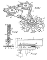
- FIG. 1 shows a device for producing packaging containers and for equipping them with a valve, simplified in a diagrammatic view
- FIG. 2 shows a device for applying small amounts of sealant to valves in cross-section
- FIG. 3 shows a side view of a mandrel of the device for forming packaging containers partly in section
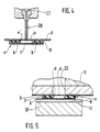
- Figure 4 shows the application part of the device according to Figure 2 on an enlarged scale in cross section
- Figure 5 shows a part of the mandrel according to Figure 3 on an enlarged scale in cross section.
- a device for producing packaging containers, such as bags b. and to equip it with a one-way or pressure relief valve v has a gradually rotated wheel 10 with a plurality of radially projecting mandrels 11.
- a blank s made of flexible packaging material is folded around the mandrel 11, so that a sleeve h is formed.
- the protruding end of the sleeve h is folded and sealed to form a dense bottom c.
- a punch 13, which is actuated by an electromagnet 14, is arranged below the circular path of the shaping mandrels 11.
- the punch 13 cuts an opening in the form of a slot or hole a with a small cross-section in the lower wall of each bag b.
- a one-way valve v is glued to the bottom of bag b, which covers and closes hole a.
- the valves v are removed from two stamps 15, 15 'alternately by two supply belts d, d', on which they releasably adhere with an adhesive layer like labels, on a peeling edge 16, 16 'and by a pivoting movement under the hole a in the bag wall brought.
- the supplied valve v is pressed against the bag b provided, where it adheres to the bag b by means of the adhesive layer.
- valves v The structure of the valves v is described for example in EP-A-0 023 703.
- a valve v consists of a base plate p with an opening o.
- a flexible film plate f is glued along two mirror-image sectors, so that the non-adhesive, central area forms two valve channels k starting from the opening o.
- Valves v assembled in this way are releasably glued onto tapes d for storage and shipping.
- a liquid sealant is introduced into the valve channels k.
- the sealant is allocated to the valves v by small-volume metering devices 19, 19 ', which are arranged at the inlet of the strips d to the peeling edge 16, 16'.
- Such a device 19, 19 '( Figure 2) has a housing with a pneumatically up and down working piston 21, the stroke of which is limited by an adjusting screw 22.
- a valve needle 24 is connected to the piston rod 23 of the working piston 21. which projects into a valve housing with a valve seat 26.
- a bore 27 adjoins the valve seat 26 and opens into a tube 28.
- the small-volume metering devices 19, 19 ' are assigned to the inlet of the belts d, d' such that when the belt d, d 'is at a standstill, the free end of the tube 28 is centered on the opening o of the base plate p of the valve and a congruent opening o' in the belt d, d 'is directed.
- a droplet of liquid is released, which is deposited on the foil plate f in the opening o of the valve v while the metering device 19 is axially displaced toward the valve v.
- the droplet runs on the film plate f, reaches the inner ends of the two valve channels k and penetrates them by capillary action.
- the opening o of the base plate p is briefly exposed to an overpressure of a gas, preferably compressed air.
- a gas preferably compressed air.
- this is carried out after the valves v have already been glued to the bags b.
- Compressed air is passed through the hole a covered by the valve v in the wall of the bag b into the opening o of the base plate p. This takes place at station X, shortly before the bags b are pulled off the shaping mandrels 11 at station XI and passed on for filling and closing.
- a channel 31 runs in each of the shaping mandrels 11 with an inlet opening 32 near the hub 10 and an outlet opening 33 in the area of coverage with the hole a of the bag b sitting on the shaping mandrel 11 .
- the channel 31 is formed in the underside of the mandrel 11 as a groove which is covered by a plate 34 containing the inlet and outlet openings 32, 33.
- an elastic sleeve 35 in the area around the inlet opening 32 is pressed close to the mandrel 11 while a shaping mandrel 11 is stationary.
- a brief pressure build-up in the opening o of the valve v is generated through a line 37, the sleeve 35, the channel 31 and the hole a in the bag wall.
- a plunger 38 which has a recess 41 in the area of coverage with the channels k of the valve v.
- the punch 38 and the casing 35 are fastened to a carrier 39, which are cyclically moved by a lifting rod 40 against the underside of a shaping mandrel 11 located at station X.
- the plunger 38 also promotes the sealing of the outlet 33 of the channel 31 and the opening o of the valve with respect to the external atmosphere.
- valves v can also be carried out. as long as the valves v still adhere to the supply belt d. Pressurizing the valves v already attached to the packaging containers has the advantage, however, that due to the small cross section of the hole a in the bag wall, no particles of the sealant can be thrown out of the chamber formed by the opening o, the foil plate f and the bag wall.
Landscapes
- Making Paper Articles (AREA)
- Closing Of Containers (AREA)
Description
- Die Erfindung geht aus von einem Verfahren zum Abdichten eines Verpackungsbehälterventils nach der Gattung des Hauptanspruchs. Bei einem beispielsweise durch die EP-A-0 012 874 bekannt gewordenen Verfahren dieser Art wird auf ein Kanalende eines Ventils eine kleine Menge eines flüssigen Dichtmittels aufgetragen, das dann durch Kapillarwirkung in den Kanal eindringt und diesen durchsetzt.
- Der Erfindung liegt die Aufgabe zugrunde, das Abdichten eines Behälterventils zu beschleunigen, insbesondere sollen auf schnellaufenden Verpackungsmaschinen abgedichtete Behälterventile dicht gemacht werden, bevor die Behälter gefüllt und verschlossen werden.
- Die Lösung dieser Aufgabe erfolgt durch das im kennzeichnenden Teil des Patentanspruches 1 angegebene Verfahren und durch die im kennzeichnenden Teil des Patentanspruchs 3 angegebenen Maßnahmen zur Durchführung des Verfahrens.
- Das erfindungsgemäße Verfahren mit den kennzeichnenden Merkmalen des Hauptanspruchs hat den Vorteil, daß das im Bereich des Kanalendes als Tropfen abgesetzte Dichtmittel durch den kurzzeitigen Gasüberdruck schnell in den Kanal getrieben wird und diesen völlig durchsetzt, so daß die Dichtigkeit des Ventils schnell erreicht und gewährleistet wird.
- Die erfindungsgemäße Vorrichtung mit den kennzeichnenden Merkmalen des Anspruchs 3 und folgender ist insbesondere für Verpackungsmaschinen vorteilhaft, auf denen Verpackungsbehälter hergestellt, mit einem Ventil versehen, gefüllt und verschlossen werden.
- Ein Ausführungsbeispiel der Erfindung ist in der Zeichnung dargestellt und in der nachfolgenden Beschreibung näher erläutert. Es zeigen Figur 1 eine Vorrichtung zum Herstellen von Verpackungsbehältern und zum Ausrüsten dieser mit einem Ventil vereinfacht in schaubildlicher Ansicht, Figur 2 eine Einrichtung zum Auftragen kleiner Dichtmittelmengen auf Ventile im Querschnitt, Figur 3 einen Dorn der Vorrichtung nach Figur 1 zum Formen von Verpackungsbehältern in Seitenansicht teilweise im Schnitt, Figur 4 den Auftragsteil der Einrichtung nach Figur 2 in vergrößertem Maßstab im Querschnitt und Figur 5 einen Teil des Formdorns nach Figur 3 in vergrößertem Maßstab im Querschnitt.
- Eine Vorrichtung zum Herstellen von Verpackungsbehältern, wie Beuteln b. und zum Ausrüsten dieser mit einem Einweg- oder Überdruckventil v hat ein schrittweise gedrehtes Rad 10 mit mehreren radial abstehenden Formdornen 11. Auf einer ersten Station I wird um den bereitstehenden Formdorn 11 ein Zuschnitt s aus flexiblem Packstoff herumgefaltet, so daß eine Hülse h entsteht. Auf folgenden Stationen IV und V wird das überstehende Ende der Hülse h zu einem dichten Boden c gefaltet und gesiegelt.
- Auf Station VII ist unterhalb des Umlaufwegs der Formdorne 11 ein Lochstempel 13 angeordnet, der von einem Elektromagnet 14 betätigt wird. Der Lochstempel 13 schneidet in die untere Wand jedes Beutels b einen Durchbruch in Form eines Schlitzes oder Loches a mit geringem Querschnitt. Darauf wird auf Station VIII auf der Unterseite des Beutels b ein Einwegventil v geklebt, welches das Loch a überdeckt und abschließt. Die Ventile v werden von zwei Stempeln 15, 15' wechselweise von zwei Vorratsbändern d, d', auf denen sie wie Etiketten lösbar mit einer Klebstoffschicht haften, an einer Schälkante 16, 16' abgenommen und durch eine Schwenkbewegung unter das Loch a in der Beutelwand gebracht. Durch Hochdrükken des Stempels 15. 15' wird das zugeführte Ventil v gegen den bereitstehenden Beutel b gedrückt, wo es mittels der Klebstoffschicht an dem Beutel b festhaftet.
- Der Aufbau der Ventile v ist beispielsweise in der EP-A-0 023 703 beschrieben. Ein solches Ventil v besteht aus einer Grundplatte p mit einem Durchbruch o. Auf der einen Seite der Grundplatte p ist ein flexibles Folienplättchen f entlang zweier spiegelbildlicher Sektoren aufgeklebt, so daß der nicht klebende, mittlere Bereich zwei von dem Durchbruch o ausgehende Ventilkanäle k bildet. Derart zusammengesetzte Ventile v sind zum Bevorraten und zum Versand auf Bändern d lösbar aufgeklebt.
- Da die Dichtigkeit solcher Ventile zu wünschen übrig läßt, wird ein flüssiges Dichtmittel in die Ventilkanäle k eingebracht. Das Dichtmittel wird den Ventilen v von Kleinstmengendosiergeräten 19, 19' zugeteilt, die am Zulauf der Bänder d zur Abschälkante 16, 16' angeordnet sind. Ein solches Gerät 19, 19' (Figur 2) hat ein Gehäuse mit einem pneumatisch auf- und abbewegten Arbeitskolben 21, dessen Hub von einer Stellschraube 22 begrenzt wird. Mit der Kolbenstange 23 des Arbeitskolbens 21 ist eine Ventilnadel 24 verbunden. die in ein Ventilgehäuse mit einem Ventilsitz 26 ragt. An den Ventilsitz 26 schließt sich eine Bohrung 27 an, die in ein Röhrchen 28 mündet. Jeweils beim Abheben der Ventilnadel 24 vom Ventilsitz 26 durch eine kurze Hubbewegung des Arbeitskolbens 21 fließt eine geringe Menge in der Größe eines kleinen Tropfens einer durch eine Öffnung 29 in dem Ventilgehäuse 20 zugeführte Flüssigkeitsmenge durch das Röhrchen 28.
- Die Kleinstmengendosiergeräte 19, 19' sind dem Zulauf der Bänder d, d' so zugeordnet, daß beim Stillstand des Bandes d, d' das freie Ende des Röhrchens 28 mittig zum Durchbruch o der Grundplatte p des Ventils und einem kongruierenden Durchbruch o' im Band d, d' gerichtet ist. Durch Betätigen des Dosiergeräts 19, 19' wird ein Tröpfchen Flüssigkeit freigegeben, das bei gleichzeitigem axialen Verschieben des Dosiergeräts 19 zum Ventil v hin, auf dem Folienplättchen f in dem Durchbruch o des Ventils v abgesetzt wird. Je nach der Viskosität des flüssigen Dichtmittels verläuft das Tröpfchen auf dem Folienplättchen f, erreicht die inneren Enden der beiden Ventilkanäle k und dringt in diese durch Kapillarwirkung ein.
- Damit das Dichtmittel die Kanäle k der Ventile v schnell und völlig durchsetzt, wird der Durchbruch o der Grundplatte p kurzzeitig einem Überdruck eines Gases, vorzugsweise Druckluft ausgesetzt. Beim beschriebenen Ausführungsbeispiel wird dies durchgeführt, nachdem die Ventile v bereits an den Beuteln b angeklebt worden sind. Dabei wird Druckluft durch das vom Ventil v abgedeckte Loch a in der Wand der Beutel b in den Durchbruch o der Grundplatte p geleitet. Dies erfolgt auf Station X, kurz bevor die Beutel b auf Station XI von den Formdornen 11 abgezogen und zum Füllen und Verschließen weitergegeben werden.
- Zum Zuführen von Druckluft zu dem Loch a in der unteren Wand des Beutels b verläuft in jedem der Formdorne 11 ein Kanal 31 mit einer Einlaßöffnung 32 nahe der Nabe 10 und einer Auslaßöffnung 33 im Deckungsbereich mit dem Loch a des auf dem Formdorn 11 sitzenden Beutels b. Der Kanal 31 ist in der Unterseite des Formdorns 11 als Nut gebildet, die von einer die Ein- und Auslaßöffnung 32, 33 enthaltenden Platte 34 abgedeckt ist. Zum Zuführen von Druckluft zum Kanal 31 wird während des Stillstands eines Formdorns 11 auf der Station X eine elastische Hü!se 35 im Bereich um die Einlaßöffnung 32 dicht am Dorn 11 angedrückt. Von einem Magnetventil 36 gesteuert wird durch eine Leitung 37, die Hülse 35, den Kanal 31 und das Loch a in der Beutelwand ein kurzzeitiger Druckaufbau im Durchbruch o des Ventils v erzeugt. Um ein übermäßiges Ausbauchen des dünnen Folienplättchens f des Ventils v zu verhindern, wird dieses dabei durch einen Stempel 38 abgestützt, der im Deckungsbereich mit den Kanälen k des Ventils v eine Aussparung 41 hat. Der Stempel 38 und die Hüise 35 sind an einem Träger 39 befestigt, welche taktweise von einer Hubstange 40 gegen die Unterseite eines auf Station X befindlichen Formdorns 11 bewegt werden. Der Stempel 38 fördert auch das Abdichten des Auslasses 33 des Kanals 31 und des Durchbruchs o des Ventils gegenüber der Außenaimosphäre.
- Ergänzend wird bemerkt, daß der Aufbau eines Gasüberdrucks im Durchbruch o der Grundplatte p der Ventile v auch durchgeführt werden kann. solange die Ventile v noch am Bevorratungsband d haften. Das Druckbeaufschlagen der an den Verpackungsbehältern bereits befestigten Ventile v hat jedoch den Vorteil, daß wegen des geringen Querschnitts des Loches a in der Beutelwand keine Teilchen des Dichtmittels aus der von dem Durchbruch o, dem Folienplättchen f und der Beutelwand gebildeten Kammer herausgeschleudert werden können.
Claims (8)
Priority Applications (1)
| Application Number | Priority Date | Filing Date | Title |
|---|---|---|---|
| AT83100390T ATE26946T1 (de) | 1982-01-29 | 1983-01-18 | Verfahren und vorrichtung zum abdichten eines verpackungsbehaelter-ventils. |
Applications Claiming Priority (2)
| Application Number | Priority Date | Filing Date | Title |
|---|---|---|---|
| DE3202851 | 1982-01-29 | ||
| DE19823202851 DE3202851A1 (de) | 1982-01-29 | 1982-01-29 | Verfahren und vorrichtung zum abdichten eines verpackungsbehaelter-ventils |
Publications (3)
| Publication Number | Publication Date |
|---|---|
| EP0085853A2 EP0085853A2 (de) | 1983-08-17 |
| EP0085853A3 EP0085853A3 (en) | 1985-01-16 |
| EP0085853B1 true EP0085853B1 (de) | 1987-05-06 |
Family
ID=6154202
Family Applications (1)
| Application Number | Title | Priority Date | Filing Date |
|---|---|---|---|
| EP83100390A Expired EP0085853B1 (de) | 1982-01-29 | 1983-01-18 | Verfahren und Vorrichtung zum Abdichten eines Verpackungsbehälter-Ventils |
Country Status (4)
| Country | Link |
|---|---|
| EP (1) | EP0085853B1 (de) |
| JP (1) | JPS58132544A (de) |
| AT (1) | ATE26946T1 (de) |
| DE (2) | DE3202851A1 (de) |
Families Citing this family (2)
| Publication number | Priority date | Publication date | Assignee | Title |
|---|---|---|---|---|
| JPH086729Y2 (ja) * | 1989-08-02 | 1996-02-28 | 藤森工業株式会社 | ガス抜き用弁の液状シール剤供給装置 |
| DE4008097A1 (de) * | 1990-03-14 | 1991-09-19 | Bosch Gmbh Robert | Verfahren und vorrichtung zum abdichten eines verpackungsbehaelter-ueberdruckventils |
Family Cites Families (1)
| Publication number | Priority date | Publication date | Assignee | Title |
|---|---|---|---|---|
| DE2856021A1 (de) * | 1978-12-23 | 1980-07-03 | Bosch Gmbh Robert | Verfahren zum abdichten eines verpackungsbehaelter-ventils |
-
1982
- 1982-01-29 DE DE19823202851 patent/DE3202851A1/de not_active Withdrawn
-
1983
- 1983-01-18 EP EP83100390A patent/EP0085853B1/de not_active Expired
- 1983-01-18 DE DE8383100390T patent/DE3371310D1/de not_active Expired
- 1983-01-18 AT AT83100390T patent/ATE26946T1/de not_active IP Right Cessation
- 1983-01-28 JP JP58011613A patent/JPS58132544A/ja active Pending
Also Published As
| Publication number | Publication date |
|---|---|
| ATE26946T1 (de) | 1987-05-15 |
| JPS58132544A (ja) | 1983-08-06 |
| DE3202851A1 (de) | 1983-08-11 |
| DE3371310D1 (en) | 1987-06-11 |
| EP0085853A2 (de) | 1983-08-17 |
| EP0085853A3 (en) | 1985-01-16 |
Similar Documents
| Publication | Publication Date | Title |
|---|---|---|
| EP0412480B1 (de) | Vorrichtung zum Füllen von Behältern | |
| DE69213337T2 (de) | Vorrichtung vom vertikalen Typ, zum Formen, Füllen und Schliessen von flexiblen Verpackungen | |
| DE19606199C1 (de) | Etikettiergerät | |
| EP0210413B1 (de) | Verfahren zum Herstellen eines Verpackungsbehälters mit einem Überdruckventil | |
| DE4018528A1 (de) | Behaeltnis aus flexiblem kunststoff zur befestigung an einer starren haftflaeche und verfahren zur befestigung des behaeltnisses an einer starren haftflaeche | |
| EP0312760B1 (de) | Verschliessvorrichtung für zweiteilige Kapseln | |
| WO1991001252A1 (de) | Verfahren zur befüllung von druckgaspackungen sowie druckgaspackung | |
| EP2528851A1 (de) | Dosiervorrichtung und dosierverfahren für flüssigkeiten | |
| DD157599A5 (de) | Klebstoffauftragsvorrichtung | |
| DE6925024U (de) | Vorrichtung zum verpacken in einer schutzatmosphaere | |
| DE3225692A1 (de) | Dosierpumpe sowie verfahren und vorrichtung zum befuellen eines mit einer dosierpumpe versehenen behaelters | |
| EP1660402A1 (de) | Gegendruck-füllvorrichtung und verfahren zum gegendruckfüllen | |
| CH575261A5 (en) | Pressurised package with spray valve for liquids - is filled before joining the flexible spray valve for eliminating leakage | |
| CH456480A (de) | Verfahren und Vorrichtung zum Füllen von Aerosol-Behältern | |
| EP0240694A2 (de) | Vorrichtung zum Herstellen von mit Flüssigkeit gefüllten Beutelpackungen | |
| DE102020131081B3 (de) | Verfahren zum Entleeren von viskosem Material aus einer beidseitig offenen Kartusche sowie hierfür geeignete Entleer-Vorrichtung | |
| EP0085853A2 (de) | Verfahren und Vorrichtung zum Abdichten eines Verpackungsbehälter-Ventils | |
| DE19853593C1 (de) | Füllvorrichtung für Kartuschen | |
| EP0336198A2 (de) | Vorrichtungen zur gesteuerten Freisetzung dosierter Mengen von in Gasen feinverteilten Flüssigkeiten | |
| DE2642889C2 (de) | Verfahren und Vorrichtung zum tropfenweisen Dosieren von flüssigen bis viskosen Medien | |
| DE2303494A1 (de) | Vorrichtung zum fuellen von behaeltern, wie patronen fuer fuellfederhalter | |
| DE1936647A1 (de) | Vorrichtung zum Etikettieren von Behaeltern aus Kunststoff | |
| DE19734109A1 (de) | Vorrichtung zum Dosieren und Abgeben einer Füllgutmenge in einen getaktet geförderten Verpackungsbehälter | |
| WO1997037894A1 (de) | Dosen- bzw. flaschen-befülleinrichtung | |
| DE69615691T2 (de) | Verfahren und Vorrichtung zum Füllen von Behältern |
Legal Events
| Date | Code | Title | Description |
|---|---|---|---|
| PUAI | Public reference made under article 153(3) epc to a published international application that has entered the european phase |
Free format text: ORIGINAL CODE: 0009012 |
|
| 17P | Request for examination filed |
Effective date: 19830118 |
|
| AK | Designated contracting states |
Designated state(s): AT BE CH DE FR IT LI NL SE |
|
| PUAL | Search report despatched |
Free format text: ORIGINAL CODE: 0009013 |
|
| AK | Designated contracting states |
Designated state(s): AT BE CH DE FR IT LI NL SE |
|
| GRAA | (expected) grant |
Free format text: ORIGINAL CODE: 0009210 |
|
| AK | Designated contracting states |
Kind code of ref document: B1 Designated state(s): AT BE CH DE FR IT LI NL SE |
|
| REF | Corresponds to: |
Ref document number: 26946 Country of ref document: AT Date of ref document: 19870515 Kind code of ref document: T |
|
| REF | Corresponds to: |
Ref document number: 3371310 Country of ref document: DE Date of ref document: 19870611 |
|
| ET | Fr: translation filed | ||
| ITF | It: translation for a ep patent filed | ||
| PLBE | No opposition filed within time limit |
Free format text: ORIGINAL CODE: 0009261 |
|
| STAA | Information on the status of an ep patent application or granted ep patent |
Free format text: STATUS: NO OPPOSITION FILED WITHIN TIME LIMIT |
|
| 26N | No opposition filed | ||
| ITTA | It: last paid annual fee | ||
| PGFP | Annual fee paid to national office [announced via postgrant information from national office to epo] |
Ref country code: AT Payment date: 19921119 Year of fee payment: 11 |
|
| PGFP | Annual fee paid to national office [announced via postgrant information from national office to epo] |
Ref country code: SE Payment date: 19921221 Year of fee payment: 11 |
|
| PGFP | Annual fee paid to national office [announced via postgrant information from national office to epo] |
Ref country code: FR Payment date: 19930126 Year of fee payment: 11 |
|
| PGFP | Annual fee paid to national office [announced via postgrant information from national office to epo] |
Ref country code: NL Payment date: 19930131 Year of fee payment: 11 |
|
| PGFP | Annual fee paid to national office [announced via postgrant information from national office to epo] |
Ref country code: BE Payment date: 19930211 Year of fee payment: 11 |
|
| PGFP | Annual fee paid to national office [announced via postgrant information from national office to epo] |
Ref country code: DE Payment date: 19930401 Year of fee payment: 11 |
|
| PGFP | Annual fee paid to national office [announced via postgrant information from national office to epo] |
Ref country code: CH Payment date: 19930402 Year of fee payment: 11 |
|
| PG25 | Lapsed in a contracting state [announced via postgrant information from national office to epo] |
Ref country code: AT Effective date: 19940118 |
|
| PG25 | Lapsed in a contracting state [announced via postgrant information from national office to epo] |
Ref country code: SE Effective date: 19940119 |
|
| PG25 | Lapsed in a contracting state [announced via postgrant information from national office to epo] |
Ref country code: LI Effective date: 19940131 Ref country code: CH Effective date: 19940131 Ref country code: BE Effective date: 19940131 |
|
| BERE | Be: lapsed |
Owner name: ROBERT BOSCH G.M.B.H. Effective date: 19940131 |
|
| PG25 | Lapsed in a contracting state [announced via postgrant information from national office to epo] |
Ref country code: NL Effective date: 19940801 |
|
| NLV4 | Nl: lapsed or anulled due to non-payment of the annual fee | ||
| PG25 | Lapsed in a contracting state [announced via postgrant information from national office to epo] |
Ref country code: FR Effective date: 19940930 |
|
| REG | Reference to a national code |
Ref country code: CH Ref legal event code: PL |
|
| PG25 | Lapsed in a contracting state [announced via postgrant information from national office to epo] |
Ref country code: DE Effective date: 19941001 |
|
| REG | Reference to a national code |
Ref country code: FR Ref legal event code: ST |
|
| EUG | Se: european patent has lapsed |
Ref document number: 83100390.0 Effective date: 19940810 |