EP0085317B1 - Universeller Binokulartubus für Mikroskope - Google Patents
Universeller Binokulartubus für Mikroskope Download PDFInfo
- Publication number
- EP0085317B1 EP0085317B1 EP83100270A EP83100270A EP0085317B1 EP 0085317 B1 EP0085317 B1 EP 0085317B1 EP 83100270 A EP83100270 A EP 83100270A EP 83100270 A EP83100270 A EP 83100270A EP 0085317 B1 EP0085317 B1 EP 0085317B1
- Authority
- EP
- European Patent Office
- Prior art keywords
- image
- tube
- prism
- fact
- mirror
- Prior art date
- Legal status (The legal status is an assumption and is not a legal conclusion. Google has not performed a legal analysis and makes no representation as to the accuracy of the status listed.)
- Expired
Links
- 230000003287 optical effect Effects 0.000 claims abstract description 3
- 230000008878 coupling Effects 0.000 claims abstract 2
- 238000010168 coupling process Methods 0.000 claims abstract 2
- 238000005859 coupling reaction Methods 0.000 claims abstract 2
- 238000003780 insertion Methods 0.000 claims description 2
- 230000037431 insertion Effects 0.000 claims description 2
- 230000000295 complement effect Effects 0.000 claims 1
- 238000010586 diagram Methods 0.000 description 3
- 239000000654 additive Substances 0.000 description 1
- 230000000996 additive effect Effects 0.000 description 1
- 238000005259 measurement Methods 0.000 description 1
Images

Classifications
-
- G—PHYSICS
- G02—OPTICS
- G02B—OPTICAL ELEMENTS, SYSTEMS OR APPARATUS
- G02B21/00—Microscopes
- G02B21/24—Base structure
-
- G—PHYSICS
- G02—OPTICS
- G02B—OPTICAL ELEMENTS, SYSTEMS OR APPARATUS
- G02B21/00—Microscopes
Definitions
- the invention relates to a binocular tube for microscopes with at least two image inputs or outputs for additional devices and a switchable turret with which the objective beam path can be switched to the eyepieces either directly or via an additional device connected to the image input or output (detour loop).
- Such tubes are known for example from DE-PS 2406415, with the additional device being a photometer attachment.
- the mirror prism
- the object is imaged on the reflecting photometer aperture via an image output and is reflected back into the eyepieces by a second image input.
- the microscopic image is then overlaid with the image of the diaphragm.
- the known tube is not readily suitable for carrying other attachments instead of the photometer device described.
- a disadvantage of the arrangement of the mirror elements described there is that light which is directed to the photometer or is reflected into the eyepieces via the rear-view mirror reflection passes several times, up to five times, through which the intensity of the beam is considerably reduced.
- GB-A-1 392 446 discloses special binocular tubes for microscopes for observation in phase or interference contrast, in which the beam path is guided through a detour loop before it reaches the eyepieces.
- Various prisms can be switched into the return line of the detour loop, through which the beam path can be wholly or partially reflected in the direction of a camera output.
- this output can not be used as an image input z.
- the additional output can be used with little effort either for reflections from the exit of the detour line as well as for reflections in the return line, while the inputs and outputs of the detour line are suitable for attaching a further additional device, for example a camera .
- a further additional device for example a camera .
- the third switch position the light is divided from the lens to the eyepiece and to the camera or from the drawing device to the eyepiece and to the camera by means of a single beam splitter surface, so that the light emanating from the objects is optimally used.
- the mirror revolver is advantageously constructed from three different prisms, each of which has a mirror surface that is in the same position in all switching positions and is used to reflect the light into the eyepieces.
- These prisms can look, for example, so that the first prism, as a double-reflecting triangular prism, reflects 100% of the incident light into the eyepieces, while the second prism in the form of a trapezoidal prism reflects the light coming from the lenses, perpendicularly onto the parallel surfaces of the prism Pass 100% in the direction of the further exit, however, the light falling vertically on one of the two side surfaces of the return line of the detour loop reflects on the base surface and also reflects 100% in the eyepieces.
- the third prism then consists of a trapezoidal prism which is broken down into an triangular prism and an additional part by an inner beam splitter layer, the triangular partial prism having the same shape as the first prism.
- the second mirror element is expediently designed as an exchange part and can optionally be introduced into its beam path by inserting it into additional openings, the axes of which each run through one of the intersection points of the first image input or output with one of the two further outputs or inputs.
- the first image opening can be used either as an exit or an entrance.
- all entrances and exits are provided with guides for the second, interchangeable mirror element, which fix its position.
- all openings can be selected as picture outputs.
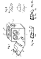
- the tube shown in Fig. 1 consists of a substantially cuboid housing 1, on the tapered front of an eyepiece holder 2 is placed such that the eyepieces 3,4 form an angle of about 30 ° with the underside of the tube 1, which on the Lens carrier of a microscope is to be put on.
- the tube 1 has eight openings, of which only five, the openings 9, 10 on the top, the opening 11 on the back and the openings 12 and 13 on the right side of the tube can be seen. In the extension of the openings 12, 13, two further openings on the left side and one opening on the front of the tube are not shown.
- a button 5 can be used to actuate a slide which has three different switching positions in which one of the three prisms shown in FIG. 2 can be pushed into the beam path.
- the openings 9-13 are each equipped with a guide 14 for the holders 15a and 15b of the second mirror elements 16a and 16b shown in FIG.
- a photometer module 19 can be placed on the top of the tube 1.
- This has an aperture in the form of an opening in a concave mirror 20, behind which a photocell 21 is arranged.
- the intermediate image formed on the mirror 20, on which the aperture opening is superimposed, is imaged once more in the eyepieces 3, 4 via the mirror 23 and the optics 22 and the mirror 18 in the tube 1 after reflection on the base surface of the trapezoidal prism 7.
- all openings are closed except for the opening 9 serving as the image output and the opening 10 serving as the image input (return line) (FIG. 1).
- a double image measuring attachment 27 can also be placed on the tube 1, which contains two beam splitters / combiners 26a and 26b with which the beam path is branched, as well as two deflecting mirrors 31 and 32, the latter of which extends perpendicular to the plane of the drawing Axis is pivotable by small amounts.
- a pivoting of the mirror 32 causes the intermediate image formed in the eyepieces to be split up for measurement purposes.
- the tube 1 carries a camera attachment 35, which receives 70% of the light transmitted by the beam splitter surface 28 in the prism 8 via the output 9. After reflection on the beam splitter surface 28, 30% of the light reaches the eyepieces 3, 4. After insertion of one of the other two prisms 7 or 6, 100% of the light coming from the objective 24 either reaches the camera 35 or the eyepieces 3, 4.
- the mirror element shown in FIG. 3 a is inserted into the opening 12, the mirror 16 of which couples the opening 11 to the optical system of the tube 1 as an additional image input.
- a projection add-on 36 is connected to this opening 11 and superimposes the image of the reticle 39 illuminated by the lamp 37 and the collector 38 with the aid of the optics 40 on the intermediate images in the eyepieces 3, 4 and on the film plane of the camera 35.
- the reticle can, for example, carry a scale to be exposed in the image and a format limit as an adjustment aid for the user.
- the projection additive 36 is to be placed on the tube 1 at the opening 10 and to attach the camera 35 to the rear opening 11.
- the mirror 16 is to be removed from the opening 12 and inserted into the opening 13 or replaced with the mirror 16b of the element shown in FIG. 3b, which is then inserted into the opening 9.
- the camera 35 or the projection attachment 36 it is also possible to attach the camera 35 or the projection attachment 36 to one of the side openings.
- two of the mirror elements shown in FIG. 3, one each inserted into the front and rear opening 11, or two of the elements shown in FIG. 3b are each inserted into the opening opposite the attached additional part.
- both devices can be operated simultaneously on the tube 1.
Landscapes
- Physics & Mathematics (AREA)
- Chemical & Material Sciences (AREA)
- Analytical Chemistry (AREA)
- General Physics & Mathematics (AREA)
- Optics & Photonics (AREA)
- Microscoopes, Condenser (AREA)
- Transition And Organic Metals Composition Catalysts For Addition Polymerization (AREA)
Description
- Die Erfindung betrifft einen Binokulartubus für Mikroskope mit mindestens zwei Bildeingängen bzw. -ausgängen für Zusatzgeräte und einem schaltbaren Spiegelrevolver, mit dem der Objektivstrahlengang wahlweise direkt oder über ein an den Bildeingang bzw. -ausgang angeschlossenes Zusatzgerät (Umwegschleife) auf die Okulare schaltbar ist.
- Derartige Tuben sind beispielsweise aus der DE-PS 2406415 bekannt, wobei es sich bei dem Zusatzgerät um einen Photometeraufsatz handelt. Bei eingeschobenem Spiegel (Prisma) wird das gesamte vom Objektiv kommende Licht in die Okulare reflektiert, während bei ausgeschobenem Spiegel das Objekt über einen Bildausgang auf die reflektierende Photometerblende abgebildet und von dieser durch einen zweiten Bildeingang in die Okulare zurückreflektiert wird. In dieser Schaltstellung ist dann das mikroskopische Bild mit dem Bild der Blende überlagert.
- Der bekannte Tubus ist nicht ohne weiteres dazu geeignet anstelle der beschriebenen Photometereinrichtung anderer Aufsätze zu tragen.
- Aus der US-PS 34 21 806 ist ein Photometermikroskop beschrieben, das einen ersten sowohl als Ausgang als auch als Eingang für die Rückspiegelung einer beleuchteten Blende benutzten Strahlzweig und einen weiteren als Ausgang für eine Aufsatzkamera genutzten, zweiten Strahlzweig aufweist (Fig. 5).
- Nachteilig an der dort beschriebenen Anordnung der Spiegelelemente ist, daß Licht, welches zum Photometer geleitet wird bzw. über die Blendenrückspiegelung in die Okulare reflektiert wird mehrmals, bis zu fünfmal, Strahlteiler passiert, durch die eine erhebliche Intensitätsminderung erfolgt.
- Aus der GB-A-1 392 446 sind spezielle Binokulartuben für Mikroskope zur Beobachtung im Phasen- bzw. Interferenzkontrast bekannt, in denen der Strahlengang über eine Umwegschleife geführt ist, bevor er die Okulare erreicht. In die Rückleitung der Umwegschleife sind verschiedene Prismen einschaltbar, durch die der Strahlengang ganz oder teilweise in Richtung auf einen Kameraausgang ausgespiegelt werden kann.
- Dieser Ausgang läßt sich jedoch nicht als Bildeingang z. B. für einen Projektor verwenden, der dem Beobachter Zusatzinformationen darbietet. Außerdem ist es nicht möglich die Umwegschleife mit den Elementen für Phasen- oder Interferenzkontrast gegen weitere Zusatzgeräte wie z. B. eine zweite Kamera etc. auszutauschen.
- Es ist die Aufgabe der vorliegenden Erfindung einen Binokulartubus zu schaffen, der zum Ansetzen verschiedenartiger Zusatzgeräte geeignet ist, an den also anstatt eines Photometeraufsatzes beispielsweise ein Photo- bzw. Kamerabaustein und ein Zeichenapparat ansetzbar sind.
- Diese Aufgabe wird durch eine Ausbildung des Tubus gemäß den im Kennzeichen des Anspruchs 1 angegebenen Merkmalen gelöst.
- In dem erfindungsgemäß aufgebauten Tubus läßt sich der zusätzliche Ausgang ohne großen Aufwand wahlweise für Ausspiegelungen aus dem Ausgang der Umwegleitung als auch für Einspiegelungen in die Rückleitung nutzen während die Ein- bzw. Ausgänge der Umwegleitung zum Ansetzen eines weiteren Zusatzgerätes, beispielsweise einer Kamera, geeignet sind. In zwei Schaltstellungen des ersten Spiegelelementes werden dabei jeweils 100% des zu nutzenden Lichtes in die Zusatzgeräte, z. B. die Kamera oder von den Zusatzgeräten, z. B. von dem Zeichenapparat in die Okulare reflektiert. In der dritten Schaltstellung erfolgt eine Aufteilung des Lichts vom Objektiv zum Okular und zur Kamera bzw. vom Zeichenapparat zum Okular und zur Kamera durch eine einzige Strahlteilerfläche, wodurch das von den Objekten ausgehende Licht also optimal genutzt wird.
- Der Spiegelrevolver ist vorteilhaft aus drei verschiedenen Prismen aufgebaut, die jeweils eine Spiegelfläche besitzen, die in allen Schaltstellungen die gleiche Lage einnimmt und zur Einspiegelung des Lichtes in die Okulare dient. Diese Prismen können beispielsweise so aussehen, daß das erste Prisma als doppelt reflektierendes Dreiecksprisma das einfallende Licht zu 100% in die Okulare spiegelt, während das zweite Prisma in der Form eines Trapezprismas das von den Objektiven kommende, senkrecht auf die parallelen Flächen des Prismas auftreffende Licht zu 100% in Richtung des weiteren Ausganges passieren läßt jedoch das senkrecht auf eine der beiden Seitenflächen fallende Licht der Rückleitung der Umwegschleife an der Basisfläche reflektiert und ebenfalls zu 100% in die Okulare einspiegelt. Das dritte Prisma besteht dann aus einem Trapezprisma, das durch eine innere Strahlteilerschicht in ein Dreiecksprisma und ein Ergänzungsteil zerlegt ist, wobei das dreieckige Teilprisma die gleiche Form wie das erste Prisma besitzt.
- Das zweite Spiegelelement ist zweckmäßig als Austauschteil ausgebildet und kann wahlweise durch Einschieben in zusätzliche Öffnungen, deren Achsen jeweils durch einen der Schnittpunkte des ersten Bildein- bzw. -ausgangs mit einem der beiden weiteren Aus- bzw. Eingänge verlaufen, in deren Strahlengang eingebracht werden. Dadurch ist die erste Bildöffnung wahlweise als Ausgang oder Eingang verwendbar.
- Zweckmäßigerweise sind alle Ein- bzw. Ausgänge mit Führungen für das zweite, austauschbare Spiegelelement versehen, die dessen Stellung festlegen. So können prinzipiell alle Öffnungen als Bildausgänge angewählt werden.
- Weitere vorteilhafte Ausgestaltungen finden sich in den Unteransprüchen und werden nachstehend anhand der Fig. 1-6 der Zeichnungen erläutert. Dabei zeigt
- Fig. 1 eine perspektivische Darstellung eines erfindungsgemäßen Tubus;
- Fig. eine Schnittzeichnung durch die drei Prismen, die mit dem Schieber 5 aus Fig. 1 schaltbar sind;
- Fig. 3a eine perspektivische Darstellung eines auswechselbaren, zweiten Spiegelelements für den Tubus aus Fig. 1;
- Fig. 3b eine andere Ausführungsform des Spiegelelements aus Fig. 3a;
- Fig. 4 eine Prinzipskizze des mit einem Photometeraufsatz versehenen Tubus aus Fig. 1;
- Fig. 5 eine Prinzipskizze eines Doppelbildmeßaufsatzes für den Tubus aus Fig. 1;
- Fig. 6 eine Prinzipskizze des mit Kameraaufsatz und angesetzter Projektionseinheit versehenen Tubus aus Fig. 1.
- Der in Fig. 1 dargestellte Tubus besteht aus einem im wesentlichen quaderförmigen Gehäuse 1, an dessen abgeschrägte Vorderseite ein Okularträger 2 derart aufgesetzt ist, daß die Okulare 3,4 etwa einen Winkel von 30° mit der Unterseite des Tubus 1 einschließen, der auf den Objektivträger eines Mikroskops aufzusetzen ist. Der Tubus 1 besitzt acht Öffnungen von denen nur fünf, die Öffnungen 9, 10 an der Oberseite, die Öffnung 11 an der Rückseite sowie die Öffnungen 12 und 13 an der rechten Seite des Tubus zu sehen sind. Nicht dargestellt sind in Verlängerung der Öffnungen 12, 13 zwei weitere Öffnungen auf der linken Seite sowie eine Öffnung auf der Vorderseite des Tubus.
- Mit einem Knopf 5 kann ein Schieber betätigt werden, der drei verschiedene Schaltstellungen besitzt, in denen eines der drei in Fig. 2 dargestellten Prismen in den Strahlengang eingeschoben werden kann.
- Die Öffnungen 9-13 sind jeweils mit einer Führung 14 für die mit einer Nut 17a bzw. 17b versehenen in Fig. dargestellten Halter 15a bzw. 15b der zweiten Spiegelelemente 16a bzw. 16b ausgestattet.
- Wie in Fig. 4 dargestellt kann auf die Oberseite des Tubus 1 ein Photometerbaustein 19 aufgesetzt werden. Dieser besitzt eine Blende in Form einer Öffnung in einem Hohlspiegel 20, hinter dem eine Photozelle 21 angeordnet ist. Das auf dem Spiegel 20 entstehende Zwischenbild, dem die Blendenöffnung überlagert ist, wird über den Spiegel 23 und die Optik 22 sowie den Spiegel 18 im Tubus 1 nach Reflexion an der Basisfläche des Trapezprismas 7 ein weiteres Mal in den Okularen 3, 4 abgebildet. In dieser Konfiguration sind alle Öffnungen bis auf die als Bildausgang dienende Öffnung 9 und die als Bildeingang (Rückleitung) dienende Öffnung 10 (Fig. 1) verschlossen.
- Anstelle des Photometerbausteins 19 kann auch ein Doppelbildmeßaufsatz 27 auf den Tubus 1 aufgesetzt werden, der zwei Strahlteiler/ Vereiniger 26a und 26b enthält, mit denen der Strahlengang verzweigt wird, sowie zwei Umlenkspiegel 31 und 32, von denen der letztere um eine senkrecht zur Zeichenebene verlaufende Achse um geringe Beträge schwenkbar ist.
- Ein Schwenken des Spiegels 32 bewirkt eine Aufspaltung des in den Okularen entstehenden Zwischenbildes für Meßzwecke.
- In Fig. 6 trägt der Tubus 1 einen Kameraaufsatz 35, der 70% des von der Strahlteilerfläche 28 in dem Prisma 8 durchgelassenen Lichtes über den Ausgang 9 erhält. 30% des Lichtes gelangen nach Reflexion an der Strahlteilerfläche 28 in die Okulare 3, 4. Nach Einschieben eines der beiden anderen Prismen 7 oder 6 gelangen jeweils 100% des vom Objektiv 24 kommenden Lichtes entweder zur Kamera 35 oder in die Okulare 3, 4.
- In die Öffnung 12 ist das in Fig. 3a dargestellte Spiegelelement eingeschoben, dessen Spiegel 16 die Öffnung 11 als zusätzlichen Bildeingang an das optische System des Tubus 1 ankoppelt. An dieser Öffnung 11 ist ein Projektionszusatz 36 angeschlossen, der das Bild der über Lampe 37 und den Kollektor 38 beleuchteten Strichplatte 39 mit Hilfe der Optik 40 den Zwischenbildern in den Okularen 3, 4 und auf der Filmebene der Kamera 35 überlagert. Die Strichplatte kann beispielsweise einen in das Bild zu belichteten Maßstab und eine Formatbegrenzung als Einstellhilfe für den Benutzer tragen.
- Es ist ohne weiteres möglich, falls es aus Platz- oder Stabilitätsgründen nötig sein sollte, den Projektionszusatz 36 auf den Tubus 1 an die Öffnung 10 anzusetzen und die Kamera 35 an die hintere Öffnung 11 anzusetzen. In dieser Anordnung ist der Spiegel 16 aus der Öffnung 12 zu entfernen und in die Öffnung 13 einzuschieben oder gegen den Spiegel 16b des in Fig. 3b gezeigten Elementes zu ersetzen, das dann in die Öffnung 9 eingeschoben wird.
- Selbstverständlich ist es auch möglich die Kamera 35 oder den Projektionszusatz 36 an eine der seitlichen Öffnungen anzusetzen. In diesem Falle werden zwei der in Fig. 3 dargestellten Spiegelelemente, je eines in die vordere und die hintere Öffnung 11 eingeschoben oder zwei der in Fig. 3b dargestellten Elemente jeweils in die dem angesetzten Zusatzteil gegenüberliegende Öffnung eingeführt.
- Setzt man abweichend von der in Fig. 6 skizzierten Konfiguration anstelle des Projektionsaufsatzes 36 eine Fernsehkamera an und benutzt anstelle eines Vollspiegels 16 einen Strahlteiler, der in die Öffnung 13 eingeschoben ist, so lassen sich beide Geräte gleichzeitig am Tubus 1 betreiben.
- Die vorstehend beschriebenen Ausführungsbeispiele stellen keine abschließende Aufzählung der Variationsmöglichkeiten des erfindungsgemäßen Binokulartubus dar. Mit dem universellen Tubus lassen sich vielmehr eine Reihe weiterer Konfigurationen realisieren, von deren Darstellung aus Platzgründen abgesehen wird.
Claims (8)
Priority Applications (1)
| Application Number | Priority Date | Filing Date | Title |
|---|---|---|---|
| AT83100270T ATE14245T1 (de) | 1982-01-30 | 1983-01-14 | Universeller binokulartubus fuer mikroskope. |
Applications Claiming Priority (2)
| Application Number | Priority Date | Filing Date | Title |
|---|---|---|---|
| DE3203142 | 1982-01-30 | ||
| DE19823203142 DE3203142A1 (de) | 1982-01-30 | 1982-01-30 | Universeller binokulartubus fuer mikroskope |
Publications (2)
| Publication Number | Publication Date |
|---|---|
| EP0085317A1 EP0085317A1 (de) | 1983-08-10 |
| EP0085317B1 true EP0085317B1 (de) | 1985-07-10 |
Family
ID=6154387
Family Applications (1)
| Application Number | Title | Priority Date | Filing Date |
|---|---|---|---|
| EP83100270A Expired EP0085317B1 (de) | 1982-01-30 | 1983-01-14 | Universeller Binokulartubus für Mikroskope |
Country Status (6)
| Country | Link |
|---|---|
| US (1) | US4518230A (de) |
| EP (1) | EP0085317B1 (de) |
| JP (1) | JPS58132714A (de) |
| AT (1) | ATE14245T1 (de) |
| CA (1) | CA1208948A (de) |
| DE (2) | DE3203142A1 (de) |
Families Citing this family (18)
| Publication number | Priority date | Publication date | Assignee | Title |
|---|---|---|---|---|
| DE3334691C2 (de) * | 1983-09-24 | 1985-11-28 | C. Reichert Optische Werke Ag, Wien | Mikroskop |
| GB2152229B (en) * | 1983-11-30 | 1987-01-14 | Mitutoyo Mfg Co Ltd | Microscope |
| DE3508306A1 (de) * | 1985-03-08 | 1986-09-11 | Fa. Carl Zeiss, 7920 Heidenheim | Mikroskoptubus |
| JPH069572B2 (ja) * | 1986-08-06 | 1994-02-09 | オリンパス光学工業株式会社 | 手術用顕微鏡 |
| DE3636616A1 (de) * | 1986-10-28 | 1988-05-05 | Zeiss Carl Fa | Photometertubus fuer ein mikroskop |
| US5007723A (en) * | 1987-05-15 | 1991-04-16 | Storz Instrument Company | Documentation illumination module for a microscope system |
| US5089909A (en) * | 1987-05-15 | 1992-02-18 | Storz Instrument Company | Documentation illumination module for a microscope system |
| US4856873A (en) * | 1987-05-15 | 1989-08-15 | Storz Instrument Company | Documentation illumination module |
| JPH03240016A (ja) * | 1990-02-19 | 1991-10-25 | Olympus Optical Co Ltd | 顕微鏡光学系 |
| IL116131A (en) * | 1995-11-24 | 1998-09-24 | Vectop Ltd | Adapter for extracting a portion of an image from an optical system or device |
| DE19622357B4 (de) * | 1996-06-04 | 2005-09-15 | Carl Zeiss Jena Gmbh | Vorrichtung zur Umschaltung der Betriebsarten eines Mikroskoptubus |
| US6061182A (en) * | 1996-11-21 | 2000-05-09 | Vectop Ltd. | Combiner for superimposing a display image on to an image of an external scene |
| US6097538A (en) * | 1998-02-03 | 2000-08-01 | Olympus Optical Co., Ltd. | Lens barrel for use in a microscope |
| DE102004048296B4 (de) | 2004-10-01 | 2018-09-20 | Carl Zeiss Microscopy Gmbh | Vorrichtung zum Umschalten der Betriebsarten eines Mikroskoptubus |
| US8089691B2 (en) * | 2007-12-10 | 2012-01-03 | Quorum Technologies Inc. | Projection device for patterned illumination and microscopy |
| USD722094S1 (en) * | 2013-08-02 | 2015-02-03 | Carl Zeiss Meditec Ag | Microscope having a handle |
| USD723079S1 (en) * | 2013-08-06 | 2015-02-24 | Carl Zeiss Meditec Ag | Operating microscope |
| JP1555090S (de) * | 2015-04-17 | 2016-08-01 |
Family Cites Families (8)
| Publication number | Priority date | Publication date | Assignee | Title |
|---|---|---|---|---|
| FR1075255A (fr) * | 1953-01-06 | 1954-10-14 | Perfectionnements apportés aux dispositifs optiques et mécaniques du microscope | |
| US2910913A (en) * | 1955-05-17 | 1959-11-03 | Zeiss Carl | Camera microscopes |
| GB862734A (en) * | 1958-05-24 | 1961-03-15 | Zeiss Stiftung | A prism combination for altering the light path through a camera-microscope |
| US2964996A (en) * | 1959-05-19 | 1960-12-20 | Leitz Ernst Gmbh | Projection microscopes |
| AT218272B (de) * | 1960-08-25 | 1961-11-27 | Reichert Optische Werke Ag | Mikro-Spektrophotometer |
| DE1215954B (de) * | 1963-02-08 | 1966-05-05 | Leitz Ernst Gmbh | Fotometer fuer Beobachtungsinstrumente, insbesondere Mikroskope |
| GB1392446A (en) * | 1971-06-07 | 1975-04-30 | Vickers Ltd | Microscopes |
| DE2406415A1 (de) * | 1973-04-04 | 1974-10-24 | Reichert Optische Werke Ag | Optische anordnung fuer mikroskope mit schraegeinblick und mit photometereinrichtung |
-
1982
- 1982-01-30 DE DE19823203142 patent/DE3203142A1/de not_active Withdrawn
-
1983
- 1983-01-14 DE DE8383100270T patent/DE3360358D1/de not_active Expired
- 1983-01-14 AT AT83100270T patent/ATE14245T1/de not_active IP Right Cessation
- 1983-01-14 EP EP83100270A patent/EP0085317B1/de not_active Expired
- 1983-01-19 US US06/459,053 patent/US4518230A/en not_active Expired - Fee Related
- 1983-01-20 JP JP58006740A patent/JPS58132714A/ja active Pending
- 1983-01-25 CA CA000420192A patent/CA1208948A/en not_active Expired
Also Published As
| Publication number | Publication date |
|---|---|
| ATE14245T1 (de) | 1985-07-15 |
| JPS58132714A (ja) | 1983-08-08 |
| DE3203142A1 (de) | 1983-08-04 |
| CA1208948A (en) | 1986-08-05 |
| EP0085317A1 (de) | 1983-08-10 |
| US4518230A (en) | 1985-05-21 |
| DE3360358D1 (en) | 1985-08-14 |
Similar Documents
| Publication | Publication Date | Title |
|---|---|---|
| DE3432635C2 (de) | ||
| EP0085317A1 (de) | Universeller Binokulartubus für Mikroskope | |
| DE3508306C2 (de) | ||
| DE4212924C2 (de) | Stereomikroskop | |
| CH646532A5 (de) | Aufsatzkamera an einem mikroskop. | |
| DE4330601A1 (de) | Suchereinrichtung | |
| EP2046027A1 (de) | Anordnung, bei der von einer Lichtquelle aus Licht auf einer Fläche gerichtet wird | |
| DE3938412A1 (de) | Mikroskop mit einem diagonal verlaufenden beobachtungsstrahlengang | |
| DE10212386B4 (de) | Umgekehrtes Mikroskop | |
| DE2051174A1 (de) | Doppelmikroskop | |
| DE3228609C2 (de) | Einrichtung zum Feststellen der Scharfeinstellung eines zweiäugigen Stereomikroskops | |
| DE4323129C2 (de) | Inverses Mikroskop | |
| DE3318011C2 (de) | Zusatzeinrichtung für Stereomikroskope | |
| DE2904821A1 (de) | Optisches system fuer ein kolposkop | |
| CH664445A5 (de) | Koaxiale auflicht-hellfeldbeleuchtung fuer stereomikroskope. | |
| DE3006657C2 (de) | ||
| DE3211084C2 (de) | Optisches Mikroskop-System | |
| EP0276303B1 (de) | Verfahren zum fotografieren mikroskopischer objekte und vorrichtung zu dessen durchführung | |
| DE3116074C2 (de) | Funduskamera zur Augenuntersuchung | |
| EP0265773B1 (de) | Photometertubus für ein Mikroskop | |
| DE1901008A1 (de) | Verfahren und Vorrichtung zur Verunreinigung oder Trennung von zwei optischen Strahlenbuendeln | |
| DE3735784C2 (de) | Mikroskop für photometrische Messungen | |
| AT314222B (de) | Mikroskop mit einem für Durchlicht- und Auflichtuntersuchungen eingerichteten Grundkörper | |
| DE102012223106B4 (de) | Weitwinkelvorsatz für ein Operationsmikroskop und System aus einem Operationsmikroskop und einem Weitwinkelvorsatz | |
| EP0433658B1 (de) | Inverses Mikroskop mit integriertem Photostrahlengang |
Legal Events
| Date | Code | Title | Description |
|---|---|---|---|
| PUAI | Public reference made under article 153(3) epc to a published international application that has entered the european phase |
Free format text: ORIGINAL CODE: 0009012 |
|
| 17P | Request for examination filed |
Effective date: 19830114 |
|
| AK | Designated contracting states |
Designated state(s): AT CH DE FR GB LI SE |
|
| GRAA | (expected) grant |
Free format text: ORIGINAL CODE: 0009210 |
|
| AK | Designated contracting states |
Designated state(s): AT CH DE FR GB LI SE |
|
| PG25 | Lapsed in a contracting state [announced via postgrant information from national office to epo] |
Ref country code: FR Free format text: THE PATENT HAS BEEN ANNULLED BY A DECISION OF A NATIONAL AUTHORITY Effective date: 19850710 |
|
| REF | Corresponds to: |
Ref document number: 14245 Country of ref document: AT Date of ref document: 19850715 Kind code of ref document: T |
|
| PG25 | Lapsed in a contracting state [announced via postgrant information from national office to epo] |
Ref country code: SE Effective date: 19850730 |
|
| REF | Corresponds to: |
Ref document number: 3360358 Country of ref document: DE Date of ref document: 19850814 |
|
| PG25 | Lapsed in a contracting state [announced via postgrant information from national office to epo] |
Ref country code: LI Effective date: 19860131 Ref country code: CH Effective date: 19860131 |
|
| EN | Fr: translation not filed | ||
| PLBE | No opposition filed within time limit |
Free format text: ORIGINAL CODE: 0009261 |
|
| STAA | Information on the status of an ep patent application or granted ep patent |
Free format text: STATUS: NO OPPOSITION FILED WITHIN TIME LIMIT |
|
| 26N | No opposition filed | ||
| REG | Reference to a national code |
Ref country code: CH Ref legal event code: PL |
|
| PGFP | Annual fee paid to national office [announced via postgrant information from national office to epo] |
Ref country code: AT Payment date: 19870121 Year of fee payment: 5 |
|
| GBPC | Gb: european patent ceased through non-payment of renewal fee | ||
| PG25 | Lapsed in a contracting state [announced via postgrant information from national office to epo] |
Ref country code: GB Effective date: 19881122 |
|
| PG25 | Lapsed in a contracting state [announced via postgrant information from national office to epo] |
Ref country code: AT Effective date: 19890114 |
|
| PG25 | Lapsed in a contracting state [announced via postgrant information from national office to epo] |
Ref country code: DE Effective date: 19900501 |