EP0085113B1 - Ignition device for internal combustion engine - Google Patents
Ignition device for internal combustion engine Download PDFInfo
- Publication number
- EP0085113B1 EP0085113B1 EP82902382A EP82902382A EP0085113B1 EP 0085113 B1 EP0085113 B1 EP 0085113B1 EP 82902382 A EP82902382 A EP 82902382A EP 82902382 A EP82902382 A EP 82902382A EP 0085113 B1 EP0085113 B1 EP 0085113B1
- Authority
- EP
- European Patent Office
- Prior art keywords
- coil
- circuit
- frame
- oscillation
- capacitor
- Prior art date
- Legal status (The legal status is an assumption and is not a legal conclusion. Google has not performed a legal analysis and makes no representation as to the accuracy of the status listed.)
- Expired
Links
Images


Classifications
-
- F—MECHANICAL ENGINEERING; LIGHTING; HEATING; WEAPONS; BLASTING
- F02—COMBUSTION ENGINES; HOT-GAS OR COMBUSTION-PRODUCT ENGINE PLANTS
- F02P—IGNITION, OTHER THAN COMPRESSION IGNITION, FOR INTERNAL-COMBUSTION ENGINES; TESTING OF IGNITION TIMING IN COMPRESSION-IGNITION ENGINES
- F02P7/00—Arrangements of distributors, circuit-makers or -breakers, e.g. of distributor and circuit-breaker combinations or pick-up devices
- F02P7/02—Arrangements of distributors, circuit-makers or -breakers, e.g. of distributor and circuit-breaker combinations or pick-up devices of distributors
- F02P7/021—Mechanical distributors
- F02P7/025—Mechanical distributors with noise suppression means specially adapted for the distributor
Definitions
- the detecting coil has windings mounted on a plate separately from the printed circuit board carrying the electronic components.
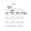
- the oscillation detecting circuit (2c) has the oscillation waveform as shown in Fig. 2(b) always entered into the same and if the oscillation amplitude becomes larger than a comparison voltage as shown in Fig. 2(b), an output signal is generated as shown in Fig. 2(c).
- This output signal is amplified by the amplifying circuit 2(d) and drives the power transistor (2e).
- a current shown in Fig. 2(d) flows through the primary winding (3a) of the ignition coil (3), and upon interrupting this current, a pulse voltage at a high voltage is generated as shown in Fig. 2(e).
- the secondary winding (3b) boosts the pulse voltage to provide a high voltage ignition pulse.
- An object of the present invention is to provide an ignition device for an internal combustion engine, having an improved compact construction.
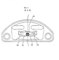
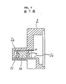
- the frame 5 forming the casing has the groove portion (5b) in the recess (5a) for the core (1b), and faults such as disconnection can be prevented by placing the leads for the coil (1c) in this groove portion (5b) in the inserting and assembling operation.
- the groove portion (5b) can be produced in the injection moulding of the frame (5), being disposed in a direction identical to the split direction of a split mold, so that it can be produced extremely easily without the necessity of special working.
Landscapes
- Engineering & Computer Science (AREA)
- Chemical & Material Sciences (AREA)
- Combustion & Propulsion (AREA)
- Mechanical Engineering (AREA)
- General Engineering & Computer Science (AREA)
- Ignition Installations For Internal Combustion Engines (AREA)
- Electrical Control Of Ignition Timing (AREA)
Applications Claiming Priority (2)
| Application Number | Priority Date | Filing Date | Title |
|---|---|---|---|
| JP1981119294U JPS5824473U (ja) | 1981-08-10 | 1981-08-10 | 内燃機関点火装置 |
| JP119294/81U | 1981-08-10 |
Publications (3)
| Publication Number | Publication Date |
|---|---|
| EP0085113A1 EP0085113A1 (en) | 1983-08-10 |
| EP0085113A4 EP0085113A4 (en) | 1984-01-10 |
| EP0085113B1 true EP0085113B1 (en) | 1987-11-11 |
Family
ID=14757843
Family Applications (1)
| Application Number | Title | Priority Date | Filing Date |
|---|---|---|---|
| EP82902382A Expired EP0085113B1 (en) | 1981-08-10 | 1982-08-10 | Ignition device for internal combustion engine |
Country Status (5)
| Country | Link |
|---|---|
| US (1) | US4516557A (cg-RX-API-DMAC7.html) |
| EP (1) | EP0085113B1 (cg-RX-API-DMAC7.html) |
| JP (1) | JPS5824473U (cg-RX-API-DMAC7.html) |
| DE (1) | DE3277634D1 (cg-RX-API-DMAC7.html) |
| WO (1) | WO1983000537A1 (cg-RX-API-DMAC7.html) |
Families Citing this family (1)
| Publication number | Priority date | Publication date | Assignee | Title |
|---|---|---|---|---|
| RU2171392C2 (ru) * | 1999-09-02 | 2001-07-27 | Репин Александр Федорович | Способ формирования многоимпульсного режима возбуждения катушки зажигания двигателя внутреннего сгорания и устройство для его осуществления |
Family Cites Families (12)
| Publication number | Priority date | Publication date | Assignee | Title |
|---|---|---|---|---|
| FR2086670A5 (fr) * | 1970-04-06 | 1971-12-31 | Compteurs Comp D | Détecteur de proximité. |
| US3853106A (en) * | 1970-08-27 | 1974-12-10 | Texaco Inc | High frequency continuous-wave ignition energy for an internal combustion engine |
| US3820521A (en) * | 1971-11-11 | 1974-06-28 | Lucas Industries Ltd | Vehicle ignitions systems |
| US3961613A (en) * | 1971-12-17 | 1976-06-08 | Texaco Inc. | Controlled spark-duration ignition system |
| JPS4917971A (cg-RX-API-DMAC7.html) * | 1972-06-07 | 1974-02-16 | ||
| US4037577A (en) * | 1974-07-08 | 1977-07-26 | Gallo Michael R | Auto ignition system |
| US4014308A (en) * | 1974-10-03 | 1977-03-29 | Delta Products, Inc. | Ignition system and apparatus and method for generating timing signals therefor |
| JPS52173A (en) * | 1975-06-23 | 1977-01-05 | Toshiba Corp | X-ray etching mask |
| US4109630A (en) * | 1976-05-17 | 1978-08-29 | The Magnavox Company | Breakerless electronic ignition system |
| US4109632A (en) * | 1976-11-01 | 1978-08-29 | Rca Corporation | GTO Ignition circuit |
| JPS55128663A (en) * | 1979-03-26 | 1980-10-04 | Hitachi Ltd | Distributor |
| JPS55139976A (en) * | 1979-04-17 | 1980-11-01 | Mitsubishi Electric Corp | Igniter for engine |
-
1981
- 1981-08-10 JP JP1981119294U patent/JPS5824473U/ja active Pending
-
1982
- 1982-08-10 WO PCT/JP1982/000313 patent/WO1983000537A1/ja not_active Ceased
- 1982-08-10 EP EP82902382A patent/EP0085113B1/en not_active Expired
- 1982-08-10 US US06/486,277 patent/US4516557A/en not_active Expired - Lifetime
- 1982-08-10 DE DE19823277634 patent/DE3277634D1/de not_active Expired
Also Published As
| Publication number | Publication date |
|---|---|
| WO1983000537A1 (fr) | 1983-02-17 |
| US4516557A (en) | 1985-05-14 |
| DE3277634D1 (cg-RX-API-DMAC7.html) | 1987-12-17 |
| EP0085113A4 (en) | 1984-01-10 |
| EP0085113A1 (en) | 1983-08-10 |
| JPS5824473U (ja) | 1983-02-16 |
Similar Documents
| Publication | Publication Date | Title |
|---|---|---|
| US5285760A (en) | Ignition coil device for an internal combustion engine | |
| US5144935A (en) | Ignition coil unit for an internal combustion engine | |
| EP0387993B1 (en) | Internal combustion engine ignition apparatus having a primary winding module | |
| US5172302A (en) | Ignition coil unit for an internal combustion engine | |
| US7710231B2 (en) | Ignition coil | |
| KR970001127B1 (ko) | 내연기관용 점화장치 및 그 제조방법 | |
| JP4872888B2 (ja) | コンデンサ放電式エンジン点火装置 | |
| US5313927A (en) | Ignition coil device for an internal combustion engine | |
| EP0085113B1 (en) | Ignition device for internal combustion engine | |
| EP0156917B2 (en) | High-energy ignition apparatus | |
| US7626481B2 (en) | Ignition coil | |
| US4499888A (en) | Ignition system for internal combustion engine | |
| US5271373A (en) | Ignition coil device for an internal combustion engine | |
| US5697352A (en) | Ignition apparatus for internal combustion engine | |
| JP3102993B2 (ja) | 内燃機関用点火コイル | |
| JPH0622386B2 (ja) | 内燃機関用磁石発電機の固定子 | |
| JPS6033352Y2 (ja) | 内燃機関点火装置 | |
| JP3714125B2 (ja) | 内燃機関用点火装置 | |
| JPH0441254Y2 (cg-RX-API-DMAC7.html) | ||
| JPS6130150B2 (cg-RX-API-DMAC7.html) | ||
| JP2796289B2 (ja) | 内燃機関用点火コイル一体型配電器 | |
| EP0131905A2 (en) | Contactless magnet ignition system | |
| JP2862760B2 (ja) | 点火コイル一体型配電器及び電磁ピックアップ | |
| JP3056002B2 (ja) | 磁石式発電機の固定子用端子装置 | |
| SU669452A1 (ru) | Статор электрической машины |
Legal Events
| Date | Code | Title | Description |
|---|---|---|---|
| PUAI | Public reference made under article 153(3) epc to a published international application that has entered the european phase |
Free format text: ORIGINAL CODE: 0009012 |
|
| 17P | Request for examination filed |
Effective date: 19830225 |
|
| AK | Designated contracting states |
Designated state(s): DE FR GB |
|
| GRAA | (expected) grant |
Free format text: ORIGINAL CODE: 0009210 |
|
| AK | Designated contracting states |
Kind code of ref document: B1 Designated state(s): DE FR GB |
|
| REF | Corresponds to: |
Ref document number: 3277634 Country of ref document: DE Date of ref document: 19871217 |
|
| ET | Fr: translation filed | ||
| PLBE | No opposition filed within time limit |
Free format text: ORIGINAL CODE: 0009261 |
|
| STAA | Information on the status of an ep patent application or granted ep patent |
Free format text: STATUS: NO OPPOSITION FILED WITHIN TIME LIMIT |
|
| 26N | No opposition filed | ||
| PGFP | Annual fee paid to national office [announced via postgrant information from national office to epo] |
Ref country code: DE Payment date: 20010806 Year of fee payment: 20 |
|
| PGFP | Annual fee paid to national office [announced via postgrant information from national office to epo] |
Ref country code: GB Payment date: 20010808 Year of fee payment: 20 |
|
| PGFP | Annual fee paid to national office [announced via postgrant information from national office to epo] |
Ref country code: FR Payment date: 20010810 Year of fee payment: 20 |
|
| REG | Reference to a national code |
Ref country code: GB Ref legal event code: IF02 |
|
| PG25 | Lapsed in a contracting state [announced via postgrant information from national office to epo] |
Ref country code: GB Free format text: LAPSE BECAUSE OF EXPIRATION OF PROTECTION Effective date: 20020809 |
|
| REG | Reference to a national code |
Ref country code: GB Ref legal event code: PE20 Effective date: 20020809 |