EP0084354A2 - Anti-skid chain with branched cross chains - Google Patents
Anti-skid chain with branched cross chains Download PDFInfo
- Publication number
- EP0084354A2 EP0084354A2 EP83100286A EP83100286A EP0084354A2 EP 0084354 A2 EP0084354 A2 EP 0084354A2 EP 83100286 A EP83100286 A EP 83100286A EP 83100286 A EP83100286 A EP 83100286A EP 0084354 A2 EP0084354 A2 EP 0084354A2
- Authority
- EP
- European Patent Office
- Prior art keywords
- chain
- tire anti
- skid chain
- connecting piece
- chain according
- Prior art date
- Legal status (The legal status is an assumption and is not a legal conclusion. Google has not performed a legal analysis and makes no representation as to the accuracy of the status listed.)
- Withdrawn
Links
Images

Classifications
-
- B—PERFORMING OPERATIONS; TRANSPORTING
- B60—VEHICLES IN GENERAL
- B60C—VEHICLE TYRES; TYRE INFLATION; TYRE CHANGING; CONNECTING VALVES TO INFLATABLE ELASTIC BODIES IN GENERAL; DEVICES OR ARRANGEMENTS RELATED TO TYRES
- B60C27/00—Non-skid devices temporarily attachable to resilient tyres or resiliently-tyred wheels
- B60C27/06—Non-skid devices temporarily attachable to resilient tyres or resiliently-tyred wheels extending over the complete circumference of the tread, e.g. made of chains or cables
Definitions
- the invention relates to a tire protection chain with a running part having branches.
- These branches form nodes in the chain network, in which several, generally three, chain sections meet. It is therefore necessary to have a Provide branch link, which holds three chain sections together, for example.
- this branching member consists of a welded ring, but this entails a number of disadvantages. First of all, this ring must be welded after it has been connected to the chain sections coming together at the node and then hardened, since it is exposed to at least the same abrasion process as the other chain links.
- the connecting piece is preferably made of steel wire and the wear piece is made of the same surface-hardened material with a tough core as the links of the chain sections. It is also advantageous for the two to interlock with each other, each essentially expanding in one plane, so that their main planes are oriented approximately perpendicular to one another.
- the joining of a plurality of chain sections at a branching point is preferably carried out by threading a pre-formed connecting piece formed from wire through the end links of the chain sections and through an open-worked wear piece and then bending them.
- Fig. 1 shows a branch in the running part of an anti-skid chain according to the invention. It denotes 1.2 Branching member, consisting of a connecting piece 1 bent from round steel and a wear piece 2.
- the material used for the former is preferably piano string steel of about 160 kg and the latter is an alloy which is customary for crawlers.
- the branching ver. binds three chain sections 3, 4a, 4b, which come together in a Y-shape at a node and form part of the running network of the anti-skid chain.
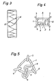
- Fig. 3 which schematically shows a top view of the tread of a tire equipped with an anti-skid chain, some possible locations of such nodes are designated by K.
- the chain sections 3 and 4a, 4b consist of chain links 5 and 6, respectively, which can be the same or different types.
- sections 4a and 4b have the same, section 3 thereof different chain links. All have a tough core in the manner customary for the running part of an anti-skid chain, surrounded by a hard surface produced by surface hardening.
- the ends of the heart-shaped connecting piece 1 are rolled up so that they form two eyes 8, in each of which an end link 6 of one of the chain sections 4a, 4b located in the figure is caught.
- the main planes of these end members like those of the end member of the section 3 located in the figure above, are thus perpendicular to the plane of the drawing, while the main plane of the connecting piece 1 is parallel to the plane of the drawing.
- a single chain link 2 which is also perpendicular to the plane of the drawing, is caught in both eyes 8 at the same time and, due to its position and position, protects the steel connecting piece 1 from contact with the road, as can be seen in particular from FIG. 2. It can also be seen from this figure that grip is particularly good if the vertical extent of the wear member 2 in this figure is equal to or greater than that of the end members 6 adjacent to it.
- Fig. 2 also shows how the elongated shape of the Link 2 and its double bracket prevent rolling on the floor, in contrast to usual, the connection piece only comprising extensive wear rings.
- the link 2 which acts as a wear piece, fills an existing gap between the sections 4a and 4b, and thereby also ensures improved traction.
- a third, closed eye 9 is also formed, which increases the stability of the whole and, above all, prevents the end links of the sections 4a, 4b from reaching the respective end 11a, 11b of the connecting piece when the anti-skid chain is not in use this eye 9 slip in, which can lead to undesirable knot formation.
- the top part 12 of the heart-shaped bent connecting piece 1 in FIG. 1 is relatively flat and the adjoining legs form an obtuse angle.
- the connector not only acts as a force-compensating balance, but also allows a certain right-left displacement of the connector and lower chain sections, relative to the upper chain section 3. This ensures that the entire chain is evenly applied Track chain on the tires possible even if the assembly is not completely uniform.
- FIG. 4 A corresponding embodiment of the branch point is shown purely schematically in FIG. 4. This figure corresponds in a stylized form to Fig.1, and parts with a corresponding function have the same characteristic numbers.
- Four chain sections 5, 6 coming together in a branching point are indicated, which are held together by a connecting piece 1. That close the connector Wear piece is designated 2.
Landscapes
- Engineering & Computer Science (AREA)
- Mechanical Engineering (AREA)
- Ropes Or Cables (AREA)
- Table Equipment (AREA)
- Forklifts And Lifting Vehicles (AREA)
- Vehicle Step Arrangements And Article Storage (AREA)
- Escalators And Moving Walkways (AREA)
- Chain Conveyers (AREA)
- Road Paving Structures (AREA)
Abstract
Description
Die Erfindung bezieht sich auf eine Reifenschutzkette mit einem Verzweigungen aufweisenden Laufteil. Diese verzweigungen bilden Knoten des Kettennetzes, in welchen mehrere, im allgemeinen drei, Kettenabschnitte zusammentreffen. Es ist somit notwendig, an diesen Stellen ein Ver- . zweigungsglied vorzusehen, welches beispielsweise drei Kettenabschnitte zusammenhält. In seiner üblichsten Ausführung besteht dieses Verzweigungsglied aus einem zugeschweissten Ring, was aber eine ganze Reihe von Nachteilen bedingt. In erster Linie muss dieser Ring nach seiner Verbindung mit den im Knotenpunkt zusammenkommenden Kettenabschnitten zugeschweisst und danach gehärtet werden, da er mindestens demselben Abriebvorgang ausgesetzt ist, wie die übrigen Kettenglieder. Praktisch ist der Verschleiss von an mehreren Punkten gehaltenen.Verzweigungsringen in der Regel sogar grösser als derjenige gewöhnlicher Kettenglieder, da beim Bremsen und Beschleunigen die Haltepunkte dazu neigen, paarweise zusammen zu rutschen, worauf der Ring etwa eine Viertelsdrehung machen kann, dann aber durch Verschränkung der Ketten in einer zur Lauffläche des Reifens mehr oder weniger senkrechten Lage blockiert wird, im Gegensatz zu einzelnen Kettengliedern, welche eine grössere Drehfreiheit haben. Fabrikationstechnisch ist das Zuschweisssen eines in drei Kettenstücke eingefädelten Ringes an sich schon umständlich, die nachträgliche Härtung aber noch problematischer, da das gesamte Y-förmige Gebilde, bestehend aus dem Ring und den drei daranhängenden, ungehärteten Kettenabschnitten zusammen behandelt werden muss. Industriell ist dies nur bei gleichzeitiger Härtung vieler solcher Gebilde, beispielsweise in einer Trommel, wirtschaftlich. Das regellose Aufeinanderliegen der Gebilde verhindert aber die wünschenswerte, gleichmässige Härtung auf eine vorgeschriebene Tiefe, wie sie für die Kettenabschnitte allein ohne weiteres, durch kontinuierliche Durchlauf-Härtung einer endlosen Kette und nachträgliches Auftrennen derselben in Kettenabschnitte, auf sehr wirtschaftliche Weise erreichbar ist. Man hat daher schon verschiedentlich nach Verzweigungsgliedern gesucht, die das Zusammenfügen von mehreren Kettenabschnitten ohne nachträgliches Schliessen durch Schweissen gestatten. Dabei haben sich schäkelartige, durch Schrauben und dergleichen schliessbare Verbindungs- und Verzweigungsglieder, wie etwa in den CH-PS 546 156 und 508 496 beschrieben, nur bei den grossen Dimensionen der als eigentliche Kettennetze ausgebildeten Gleitschutzvorrichtungen für Baumaschinen und dergleichen, als brauchbar erwiesen. Solche Glieder sind jedoch wegen ihrer Sperrigkeit, sowie aus Kosten- und Gewichtsgründen für die sogenannten Schneeketten leichterer Fahrzeuge ungeeignet. Dasselbe gilt für massive, entweder nach der Art von Brummel-Haken formschlüssig mit anderen Gliedern des Netzes verbundenen, oder zu diesem Zweck mit Schlüssellochartigen Durchbrüchen versehene Verbindungsglieder, von denen die CH-PS 551 239 einige Varianten zeigt. Andererseits bleibt die Verwendung von durch Nieten, Stiftverbindungen usw. geschlossenen Verbindungsglieder, wie etwa in der CH-PS 589 523 vorgeschlagen, aus Preisgründen sowie wegen ihrer grösseren Anfälligkeit gegen Abnützung, auf Reparaturzwecke beschränkt. Der an sich naheliegende Gebrauch eines einfachen, aus Stahl gefertigten und zu einem offenen Ring vorgebogenen Verzweigungsgliedes, welches nach Einfädeln in die Endglieder mehrerer Kettenabschnitte zugebogen, nicht aber zugeschweisst wird, hat sich nicht bewährt, zur Hauptsache weil er durch die zeitweise grossen auftretenden Kräfte aufgebogen wird. Es stellt sich also die Aufgabe, eine Gleitschutzkette zu schaffen, deren Verzweigungsglieder bei der Kettenherstellung in die Endglieder von schon gehärteten Kettenabschnitten eingeführt und ohne Schweissen, Schrauben oder Nieten sowie ohne einer nachträglichen Wärmebehandlung zu bedürfen, endgültig mit diesen verbunden werden können.The invention relates to a tire protection chain with a running part having branches. These branches form nodes in the chain network, in which several, generally three, chain sections meet. It is therefore necessary to have a Provide branch link, which holds three chain sections together, for example. In its most common version, this branching member consists of a welded ring, but this entails a number of disadvantages. First of all, this ring must be welded after it has been connected to the chain sections coming together at the node and then hardened, since it is exposed to at least the same abrasion process as the other chain links. In practice, the wear of branching rings held at several points is usually even larger than that of ordinary chain links, since when braking and accelerating the breakpoints tend to slide together in pairs, whereupon the ring can make about a quarter turn, but then by twisting the chains is blocked in one to the tread of the tire more or less vertical position, as opposed to individual chain links, which have a greater D rehfreiheit. In terms of manufacturing technology, the welding of a ring threaded into three chain pieces is in itself already cumbersome, the subsequent hardening is even more problematic, since the entire Y-shaped structure, consisting of the ring and the three attached, unhardened chain sections, has to be treated together. In industry, this is only economically viable if many such structures are hardened simultaneously, for example in a drum. However, the random stacking of the structures prevents the desirable, uniform hardening to a prescribed depth, as can be achieved for the chain sections alone, by continuous continuous hardening of an endless chain and subsequent separation of the chain sections, in a very economical manner. There have therefore been various searches for branching links which allow the joining of several chain sections without subsequent closing by welding. Shackle-like connecting and branching links which can be closed by screws and the like, as described for example in CH-PS 546 156 and 508 496, have proven to be useful only in the large dimensions of the anti-skid devices for construction machines and the like designed as actual chain nets. However, such links are unsuitable for the so-called snow chains of lighter vehicles because of their bulkiness and for reasons of cost and weight. The same applies to solid connecting links, either connected positively to other links in the network in the manner of humming hooks, or for this purpose provided with keyhole-like openings, of which the CH-PS 551 239 shows some variants. On the other hand, the use of connecting members closed by rivets, pin connections, etc., as proposed in CH-PS 589 523, remains limited to repair purposes for price reasons and because of their greater susceptibility to wear. The obvious use of a simple, made of steel and one Open ring pre-bent branch link, which is bent after threading into the end links of several chain sections, but not welded, has not proven itself, mainly because it is bent up by the occasionally large forces. It is therefore the task to create an anti-skid chain, the branching links of which are introduced into the end links of already hardened chain sections during chain production and can be finally connected to them without welding, screwing or riveting and without subsequent heat treatment.
Erfindungsgemäss wird dies durch die in Anspruch 1 definierte Anordnung erreicht. Dabei wird das Verbindungsstück vorzugsweise aus Stahldraht und das Abnützungsstück aus demselben oberflächengehärteten Material mit zähem Kern, wie die Glieder der Kettenabschnitte, gefertiat. Auch ist es vorteilhaft die beiden, sich je im wesentlichen in einer Ebene ausdehnenden Stücke so ineinander zu verschränken, dass ihre Hauptebenen etwa senkrecht zueinander ausgerichtet sinä. Das Zusammenfügen mehrer Kettenabschnitte an einer Verzweigungsstelle erfolgt vorzugsweise, indem ein aus Draht gebildetes, vorgeformtes Verbindungstück durch die Endglieder der Kettenabschnitte und durch ein durchbrochenes Abnützungsstück gefädelt und danach zugebogen wird.According to the invention, this is achieved by the arrangement defined in claim 1. The connecting piece is preferably made of steel wire and the wear piece is made of the same surface-hardened material with a tough core as the links of the chain sections. It is also advantageous for the two to interlock with each other, each essentially expanding in one plane, so that their main planes are oriented approximately perpendicular to one another. The joining of a plurality of chain sections at a branching point is preferably carried out by threading a pre-formed connecting piece formed from wire through the end links of the chain sections and through an open-worked wear piece and then bending them.
Es bietet die Erfindung eine Reihe von Vorteilen. So können insbesondere aus einer gleichmässig gehärteten Endloskette herausgetrennte Kettenabschnitte ohne spezielle Schweissapparatur durch einfache Verformungsarbeit zusammengesetzt werden, ohne dass eine nachträgliche Wärmebehandlung nötig wäre. Das für das Verbindungsstück verwendete Material kann aus einem bezüglich seiner Verformungseigenschaften optimal gewählten Material bestehen, welches weder schweissbar, noch gegen durch die Fahrbahn bewirkten Abrieb widerstandsfähig sein muss. Denn da das Verbindungsstück je einmal durch mindestens drei Kettenendglieder, und zweimal durch das Abnützungsstück hindurchtritt, wird es an mindestens fünf Stellen im Abstand von der Fahrbahn gehalten, die es somit praktisch nicht berühden kann. Die Existenz von drei getrennten Oeffnungen, in welchen Kettenendglieder gefangen sind, verhindert das sonst häufig auftretende Zusammenrutschen mehrerer Endglieder, nach welchem das Verzweigungsglied praktisch nur noch an zwei diametral entgegengesetzten Stellen gehalten wird, und sich um die diese Stellen verbindende Diagonale drehen kann. Da die Drehung, infolge Verschränkung der Ketten, vor einer halben Umdrehung aufhört, entsteht der berüchtigte, bevorzugte Abrieb der in einer aufgestellten Lage festgehaltenen bekannten Verzweigungsgliedern. Bei der Erfindung werden die gefangenen Kettenendglieder in genügendem Abstand voneinander gehalten, um das Kippen um eine bevorzugte Diagonale zu verhindern. Da sich zudem das vom Verbindungsstück zweimal durchdrungene Verschleissstück nicht drehen, und demnach nicht auf der Fahrbahn abrollen kann, wird ein weiterer gravierender Nachteil bekannter, mit Ver- schleissringen versehener Verzweigungsglieder vermieden. Weitere vorteilhafte Eigenschaften ergeben sich aus der folgenden Beschreibung bevorzugter Ausführungsbeispiele anhand der Zeichnungen. Es zeigen:
- Fig. 1 eine dreiteilige Verzweigungsstelle im Laufteil einer erfindungsgemässen Ketten,
- Fig. 2 einen Schnitt längs der Linie II-II der Fig.1,
- Fig. 3 die Lage der Verzweigungsstellen bei einer auf einem Reifen aufgezogenen Kette, und
- Fig. 4 und 5 Schemas einer vierteiligen bzw. dreiteiligen Verzweigungsstelle.
- 1 shows a three-part branching point in the running part of a chain according to the invention,
- 2 shows a section along the line II-II of FIG. 1,
- Fig. 3 shows the location of the branching points in a mounted on a tire chain, and
- 4 and 5 schemes of a four-part and three-part branching point.
Fig. Fig. 1 zeigt eine Verzweigung im Laufteil einer erfindungsgemässen Gleitschutzkette. Es bezeichnen 1,2 ein Verzweigungsglied, bestehend aus einem aus Rundstahl gebogenen Verbindungsstück 1 und einem Verschleissstück 2. Als Material wird für ersteres vorzugsweise Klaviersaitenstahl von etwa 160 kg verwendet und für letzteres einefür Laufketten übliche Legierung. Das Verzweigungsglied ver-. bindet drei in einem Knotenpunkt Y-förmig zusammenkommende Kettenabschnitte 3, 4a, 4b, die einen Teil des Laufnetzes der Gleitschutzkette bilden. In Fig. 3, welche schematisch eine Aufsicht auf die Lauffläche eines mit einer Gleitschutzkette bestückten Reifens zeigt, sind einige mögliche Lagen solcher Knotenpunkte mit K bezeichnet. Die Kettenabschnitte 3 und 4a, 4b bestehen aus Kettengliedern 5, respektive 6, welche gleich- oder verschiedenartig sein können. Im vorliegenden Beispiel weisen die Abschnitte 4a und 4b gleiche, der Abschnitt 3 davon unterschiedliche Kettenglieder auf. Alle weisen in der für den Laufteil einer Gleitschutzkette üblichen Weise einen zähen Kern, umgeben von einer durch Oberflächenhärtung erzeugen harten Oberfläche auf. Die Enden des herzförmig gebogenen Verbindungsstückes 1 sind so eingerollt, dass sie zwei Augen 8 bilden, in denen je ein Endglied 6 eines der in der Figur untenliegenden Kettenabschnitte 4a,4b gefangen ist. Die Hauptebenen dieser Endglieder, wie auch diejenigen des Endgliedes des in der Figur oben befindlichen Abschnittes 3 liegen somit senkrecht zur Zeichnungsebene, während die Hauptebene des Verbindungsstückes 1 parallel zur Zeichnungsebene liegt. Ein einzelnes Kettenglied 2 mit ebenfalls zur Zeichenebene senkrechten Hauptebene, ist gleichzeitig in beiden Augen 8 gefangen und schützt durch seine Lage und Stellung das stählerne Verbindungsstück 1 vor Berührung mit der Fahrbahn, wie insbesondere aus Fig. 2 ersichtlich. Aus dieser Figur ersieht man auch, dass die Bodenhaftung besonders gut wird, wenn die in dieser.Figur vertikal Ausdehnung des Verschleissgliedes 2 gleich oder grösser wie diejenige der ihm benachbarten Endglieder 6 ist.Fig. 1 shows a branch in the running part of an anti-skid chain according to the invention. It denotes 1.2 Branching member, consisting of a connecting piece 1 bent from round steel and a
Die Fig. 2 zeigt auch, wie die längliche Form des Gliedes 2 und seine zweifache Halterung ein Rollen am Boden verhindern, im Gegensatz zu üblichen, das Verbindungsstück nur einfach umfassenden Abnützungsringen.Fig. 2 also shows how the elongated shape of the
Zu Fig. 1 zurückkehrend ist zu bemerken, dass das als Verschleissstück wirkende Glied 2 eine an sich zwischen den Abschnitten 4a und 4b bestehende Lücke füllt, und auch dadurch eine verbesserte Bodenhaftung gewährleistet. Durch das Schliessen dieser Lücke wird ausserdem ein drittes, geschlossenes Auge 9 gebildet, was die Stabilität des Ganzen erhöht, und vor allem verhindert, dass bei Nichtgebrauch der Gleitschutzkette die Endglieder der Abschnitte 4a, 4b bis an das jeweilige Ende 11a, 11b des Verbindungsstückes in dieses Auge 9 hineinrutschen, was zu unerwünschter Knotenbildung führen kann.Returning to FIG. 1, it should be noted that the
Der in Fig. 1 obenliegende Scheitelteil 12 des herzförmig gebogenen Verbindungsstückes 1 ist verhältnismässig flach und die daran anschliessenden Schenkel bilden einen stumpfen Winkel. Dadurch wirkt das Verbindungsstück bei ungleichem Zug an den unteren Kettenabschnitten 4a, 4b nicht nur als eine kräfteausgleichenden Waage, sondern gestattet auch eine gewisse rechts-links-Verschiebung von Verbindungsstück und unteren Kettenabschnitten, gegenüber dem oberen Kettenabschnitt 3. Dadurch wird ein gleichmässiges Anliegen der gesamten Laufkette an den Reifen auch bei nicht vollkommen gleichmässiger Montage möglich.The
Bei gewissen Geometrien von Gleichschutzketten treten Knotenpunkte auf, in denen nicht drei, sonder vier Kettenabschnitte zusammenlaufen. Eine entsprechende Ausführungsform der Verzweigungsstelle ist in Fig. 4 rein schematisch dargestellt. Diese Figur entspricht in stilisierter Form der Fig.1, und Teile mit entsprechender Funktion tragen dieselben Kennzahlen. Es sind vier, in einer Verzweigungsstelle zusammenkommende Kettenabschnitte 5,6 angedeutet, welche durch ein Verbindungsstück 1 zusammengehalten werden. Das das Verbindungsstück schliessenäe Verschleissstück ist mit 2 bezeichnet. Zwei weitere mögliche Varianten ergeben sich z.B., wenn man die rechte, beziehungsweise linke Hälfte der Fig. 4 an. der Achse A spiegelt; es sind aber andere Formgebungen, etwa mit aussenliegendem Auge 8, ohne weiteres denkbar, wie etwa in Fig. 5 für einen dreiteiligen Knotenpunkt skizziert.With certain geometries of equal protection chains, nodes occur in which not three but four chain sections converge. A corresponding embodiment of the branch point is shown purely schematically in FIG. 4. This figure corresponds in a stylized form to Fig.1, and parts with a corresponding function have the same characteristic numbers. Four
Claims (10)
Applications Claiming Priority (2)
| Application Number | Priority Date | Filing Date | Title |
|---|---|---|---|
| CH346/82A CH654532A5 (en) | 1982-01-20 | 1982-01-20 | SLIP PROTECTION CHAIN WITH BRANCHED RUNNING PART. |
| CH346/82 | 1982-01-20 |
Publications (2)
| Publication Number | Publication Date |
|---|---|
| EP0084354A2 true EP0084354A2 (en) | 1983-07-27 |
| EP0084354A3 EP0084354A3 (en) | 1986-08-06 |
Family
ID=4184916
Family Applications (1)
| Application Number | Title | Priority Date | Filing Date |
|---|---|---|---|
| EP83100286A Withdrawn EP0084354A3 (en) | 1982-01-20 | 1983-01-14 | Anti-skid chain with branched cross chains |
Country Status (4)
| Country | Link |
|---|---|
| EP (1) | EP0084354A3 (en) |
| CH (1) | CH654532A5 (en) |
| DE (2) | DE3204374A1 (en) |
| NO (1) | NO830177L (en) |
Cited By (1)
| Publication number | Priority date | Publication date | Assignee | Title |
|---|---|---|---|---|
| EP0300289A2 (en) * | 1987-07-24 | 1989-01-25 | Milz Produkte AG | Attaching method for two pieces of an antislip chain, and attaching element for this purpose |
Citations (7)
| Publication number | Priority date | Publication date | Assignee | Title |
|---|---|---|---|---|
| FR20650E (en) * | 1915-12-14 | 1918-11-04 | Jules Fazan | Non-slip protective metal net for wheel tires |
| CH113480A (en) * | 1925-03-09 | 1926-01-02 | Union Ag | Anti-skid chain for rubber tires on vehicles. |
| US1855279A (en) * | 1929-11-28 | 1932-04-26 | Borg Gustaf Henning | Antiskid device for tires |
| DE724096C (en) * | 1940-11-23 | 1942-08-18 | Anton Oelsner | Angled open link for snow chains |
| DE738849C (en) * | 1940-05-25 | 1943-09-03 | Otto Bornemann & Co | Anti-skid chain composed of individual parts |
| FR1304668A (en) * | 1961-03-04 | 1962-09-28 | Anti-slip chain for automobile car | |
| CH487004A (en) * | 1968-05-02 | 1970-03-15 | Erlau Ag Eisen Drahtwerk | Replacement link for tire anti-skid chains |
-
1982
- 1982-01-20 CH CH346/82A patent/CH654532A5/en not_active IP Right Cessation
- 1982-02-09 DE DE19823204374 patent/DE3204374A1/en not_active Withdrawn
- 1982-02-09 DE DE19828203360U patent/DE8203360U1/en not_active Expired
-
1983
- 1983-01-14 EP EP83100286A patent/EP0084354A3/en not_active Withdrawn
- 1983-01-19 NO NO830177A patent/NO830177L/en unknown
Patent Citations (7)
| Publication number | Priority date | Publication date | Assignee | Title |
|---|---|---|---|---|
| FR20650E (en) * | 1915-12-14 | 1918-11-04 | Jules Fazan | Non-slip protective metal net for wheel tires |
| CH113480A (en) * | 1925-03-09 | 1926-01-02 | Union Ag | Anti-skid chain for rubber tires on vehicles. |
| US1855279A (en) * | 1929-11-28 | 1932-04-26 | Borg Gustaf Henning | Antiskid device for tires |
| DE738849C (en) * | 1940-05-25 | 1943-09-03 | Otto Bornemann & Co | Anti-skid chain composed of individual parts |
| DE724096C (en) * | 1940-11-23 | 1942-08-18 | Anton Oelsner | Angled open link for snow chains |
| FR1304668A (en) * | 1961-03-04 | 1962-09-28 | Anti-slip chain for automobile car | |
| CH487004A (en) * | 1968-05-02 | 1970-03-15 | Erlau Ag Eisen Drahtwerk | Replacement link for tire anti-skid chains |
Cited By (2)
| Publication number | Priority date | Publication date | Assignee | Title |
|---|---|---|---|---|
| EP0300289A2 (en) * | 1987-07-24 | 1989-01-25 | Milz Produkte AG | Attaching method for two pieces of an antislip chain, and attaching element for this purpose |
| EP0300289A3 (en) * | 1987-07-24 | 1989-04-05 | Milz Produkte Ag | Attaching method for two pieces of an antislip chain, and attaching element for this purpose |
Also Published As
| Publication number | Publication date |
|---|---|
| NO830177L (en) | 1983-07-21 |
| DE3204374A1 (en) | 1983-07-28 |
| EP0084354A3 (en) | 1986-08-06 |
| DE8203360U1 (en) | 1982-08-05 |
| CH654532A5 (en) | 1986-02-28 |
Similar Documents
| Publication | Publication Date | Title |
|---|---|---|
| DE602005001846T2 (en) | BAND WITH OPENINGS USED FOR SUPPORTING AND GUIDING CLOTHING IN HANGING SUPPORT SYSTEMS | |
| EP0084354A2 (en) | Anti-skid chain with branched cross chains | |
| DE1755524B2 (en) | Bridge link for tire protection chains | |
| CH649741A5 (en) | ANTI-SLIP CHAIN FOR VEHICLE TIRES. | |
| EP0155227B1 (en) | Antiskid chain | |
| DE1924969C3 (en) | Vertical link for chain strands of sliding or Tire protection chains or verticalless support links arranged on horizontal links | |
| CH661009A5 (en) | TIRE CHAIN AND METHOD FOR THE PRODUCTION THEREOF. | |
| DE2404055A1 (en) | TIRE PROTECTION CHAIN | |
| DE3212364C2 (en) | Tire chain, in particular anti-skid chain | |
| DE3305124C2 (en) | ||
| EP0125676B1 (en) | Anti-skid device for vehicle tyres | |
| DE932416C (en) | Endless conveyor with link chains (steel link belt) | |
| CH615392A5 (en) | Tyre chain for vehicle wheels | |
| DE10256707B4 (en) | Support member for use in a tire chain | |
| AT501232B1 (en) | SUPPORT MEMBER FOR USE IN A TIRE CHAIN AND TIRE CHAIN WITH SUD STAFF MEMBERS | |
| CH639607A5 (en) | Anti-skid chain for vehicle wheels | |
| DE3245513A1 (en) | Device for suspending a load on adjacent rock anchors in mining and tunnelling | |
| DE7437538U (en) | PROTECTIVE CHAIN FOR VEHICLE TIRES | |
| DE1813681A1 (en) | Tire protection or anti-skid net for vehicle tires | |
| DE1186699B (en) | Block chain | |
| CH629706A5 (en) | TIRE CHAIN. | |
| DE7026826U (en) | DRESSAGE COLLAR FOR DOGS. | |
| DE1755270A1 (en) | Tire protection or anti-skid net for vehicle tires | |
| DE1036189B (en) | Wire warping tip for the construction of the pit, especially for the extension of the route | |
| DE6608398U (en) | TIRE PROTECTION OR SLIDE PROTECTION CHAIN. |
Legal Events
| Date | Code | Title | Description |
|---|---|---|---|
| PUAI | Public reference made under article 153(3) epc to a published international application that has entered the european phase |
Free format text: ORIGINAL CODE: 0009012 |
|
| AK | Designated contracting states |
Designated state(s): AT BE DE FR IT |
|
| PUAL | Search report despatched |
Free format text: ORIGINAL CODE: 0009013 |
|
| AK | Designated contracting states |
Kind code of ref document: A3 Designated state(s): AT BE DE FR IT |
|
| STAA | Information on the status of an ep patent application or granted ep patent |
Free format text: STATUS: THE APPLICATION IS DEEMED TO BE WITHDRAWN |
|
| 18D | Application deemed to be withdrawn |
Effective date: 19870209 |