EP0084121A1 - Servo write head and method of writing magnetic servo information - Google Patents
Servo write head and method of writing magnetic servo information Download PDFInfo
- Publication number
- EP0084121A1 EP0084121A1 EP82111566A EP82111566A EP0084121A1 EP 0084121 A1 EP0084121 A1 EP 0084121A1 EP 82111566 A EP82111566 A EP 82111566A EP 82111566 A EP82111566 A EP 82111566A EP 0084121 A1 EP0084121 A1 EP 0084121A1
- Authority
- EP
- European Patent Office
- Prior art keywords
- track
- servo
- head
- writing
- fringe field
- Prior art date
- Legal status (The legal status is an assumption and is not a legal conclusion. Google has not performed a legal analysis and makes no representation as to the accuracy of the status listed.)
- Ceased
Links
Images


Classifications
-
- G—PHYSICS
- G11—INFORMATION STORAGE
- G11B—INFORMATION STORAGE BASED ON RELATIVE MOVEMENT BETWEEN RECORD CARRIER AND TRANSDUCER
- G11B5/00—Recording by magnetisation or demagnetisation of a record carrier; Reproducing by magnetic means; Record carriers therefor
- G11B5/012—Recording on, or reproducing or erasing from, magnetic disks
-
- G—PHYSICS
- G11—INFORMATION STORAGE
- G11B—INFORMATION STORAGE BASED ON RELATIVE MOVEMENT BETWEEN RECORD CARRIER AND TRANSDUCER
- G11B5/00—Recording by magnetisation or demagnetisation of a record carrier; Reproducing by magnetic means; Record carriers therefor
- G11B5/127—Structure or manufacture of heads, e.g. inductive
- G11B5/31—Structure or manufacture of heads, e.g. inductive using thin films
- G11B5/3109—Details
- G11B5/3116—Shaping of layers, poles or gaps for improving the form of the electrical signal transduced, e.g. for shielding, contour effect, equalizing, side flux fringing, cross talk reduction between heads or between heads and information tracks
-
- G—PHYSICS
- G11—INFORMATION STORAGE
- G11B—INFORMATION STORAGE BASED ON RELATIVE MOVEMENT BETWEEN RECORD CARRIER AND TRANSDUCER
- G11B5/00—Recording by magnetisation or demagnetisation of a record carrier; Reproducing by magnetic means; Record carriers therefor
- G11B5/48—Disposition or mounting of heads or head supports relative to record carriers ; arrangements of heads, e.g. for scanning the record carrier to increase the relative speed
- G11B5/58—Disposition or mounting of heads or head supports relative to record carriers ; arrangements of heads, e.g. for scanning the record carrier to increase the relative speed with provision for moving the head for the purpose of maintaining alignment of the head relative to the record carrier during transducing operation, e.g. to compensate for surface irregularities of the latter or for track following
- G11B5/596—Disposition or mounting of heads or head supports relative to record carriers ; arrangements of heads, e.g. for scanning the record carrier to increase the relative speed with provision for moving the head for the purpose of maintaining alignment of the head relative to the record carrier during transducing operation, e.g. to compensate for surface irregularities of the latter or for track following for track following on disks
- G11B5/59633—Servo formatting
Definitions
- This invention pertains to magnetic media storage devices wherein data and servo information are stored in adjoining tracks and more particularly to a structure and method for more effectively writing servo data on the media of such a device.
- Servo tracks for magnetic media recording are normally offset a half-track pitch from the associated data tracks whereupon the servo reading is accomplished by sensing the signals from two adjoining servo tracks and establishing the proper data track location by adjusting the servo head position until the signals read from the two interfacing tracks are of equal magnitude indicative of positioning on the centerline of the associated data track or tracks.
- Data tracks are spaced from adjoining data tracks and only occupy about 80 per cent of the track pitch; however, servo tracks are recorded with a width equal to the full track pitch or spacing between adjoining track centerlines. Consequently any condition that impairs the servo track width makes the system less accurate and less effective.
- the servo write head of the present invention has a configuration with a first transverse side of the head formed to minimize the writing of fringe fields while the second side, the transverse side opposite the first side, is configured to provide a low pole piece reluctance and reasonable write head efficiency. This permits compression of the field at the first transverse side.
- the fact that the structure of the second transverse side causes the writing of a wide fringe field is of no importance since servo writing using the head is accomplished by starting with the farthest servo track at the first side of the servo write head so that the narrow fringe field adjoins each previously written traclt, and the wide fringe field region adjacent the head second transverse side is overwritten by the next succeeding servo track.
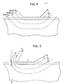
- the head assembly carried by the substrate 25 "flies" above the media 30 on an air bearing in a generally parallel attitude. Accordingly, the orientation of the head assembly parts and in particular the pole layer 7 have with respect to the lower surface 26 of substrate 25, is the same orientation that is maintained with the upper, cooperating surface of the magnetic media 30.
- a first side 33 of the pole piece forms an obtuse angle 9L with the substrate surface 26.
- the second side 34 at the opposite transverse side of the transducing gap 11 forms an acute angle OR with the substrate lower surface 26. Since the field at this side of the head is of no consequence, the angle can be as small as required for mechanical purposes and core efficiency. This may be as little as 30° or less.
- FIG. 4 shows a typical, current design ferrite head with 45° side walls on the read/write core.
- This 200 to 300 microinch dead band or band of no signal represents about a 15 per cent to 20 per cent reduction of signal for current magnetic disk designs, but is likely to become 30 per cent to 50 per cent degradation of signal in future magnetic disk drives where double track density or more will reduce the track pitch to half or less of the present track pitch.
- a partial erasure also occurs out to about 1000 microinches causing a non-uniform reduction of the signal across the track.
- the 500 oersted, 200 oersted and 100 oersted field levels which project laterally from side of the pole piece, where the obtuse angle eL occurs are less than half the width when compared to the corresponding field levels in FIG. 4.
- an extended fringe field region At the opposite side of the pole piece where the acute angle eR occurs there exists an extended fringe field region.
- angle eR By making angle eR smaller, it is possible to make OL larger causing compression of the field at the left side of the figure.
- the wide fringe field at the right side of FIG. 3 caused by the reduction of angle OR is unimportant, since as each track is written from left to right, the data written in the wide fringe field during the writing of one track is overwritten by the head during the writing of the next successive track.
- the transition region between tracks is therefore determined solely by the narrow fringe field at the left side of the head as seen in FIG. 3.
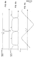
- FIGS. 5 and 6 are corresponding representations wherein FIG. 5 shows conditions related to a 45° ferrite head and FIG. 6 shows conditions related to the servo write head of the present invention having an obtuse angle at one pole side.
- the ordinate value is magnetization density and the abscissa is radial displacement along the data surface.
- FIG. 5A shows the effect of writing the current track (last track magnetization) on the magnetization of the data written on the prior adjoining track (previously written track).
- the left side of the servo head is positioned as indicated by the vertical line D.
- the previously written track has one set of information recorded with a level of magnetization as indicated by curve A and the current track has a second set of information as indicated by the curve B.
- the horizontal dotted line C represents the magnetization level of curve A prior to writing the current track as represented by curve B.
- FIG. 5B shows a series of track interfaces written with alternating track types as shown by the A and B curves.
- FIG. 5C shows the position error signal (PES) as generated by some standard method for distinguishing tracks A and B as the ordinate and the track centerline position as the abscissa.
- PES position error signal
- FIGS. 5A and 5B show the fringe field effect of curve B upon curve A wherein some erasure occurs over approximately 80% of the track pitch and generates a series of irregular curves having a reduced magnetization amplitude at the right side of each track magnetization curve.
- the zero value position error signal (FIG. 5C) is displaced about 20% of the track pitch since the integral sum of the area under the A curve must equal the integrated sum of the area under the B curve.
- FIG. 6 shows the same information with respect to tracks written using the servo head design of the present invention which suppresses the fringe fields at the side of the servo head which is of interest.
- the existence of the reduced fringe field reduces the side erasure resulting in a smaller asymmetry in the magnetization curve.
- the position error signal zero position F experiences a significantly lesser displacement from the head interface.
- the zero PES is identified as the centerline of the associated data track.
- the most significant effect of the more symmetrical magnetization curves is the generation of greater linearity of the position error signal.
- the length of the linear portion of the position error signal curve of FIG. 6C is almost twice that of 5C. Ideally the position error signal of FIGS. 5C and 6C would be triangular to maximize the linearity.
- the head design of this invention has been illustrated as a thin film head assembly since this would be the easiest technology in which to fabricate the transducer with the critical pole piece side at angle eL. It is also possible for this head design to be built of the conventional ferrite materials by sawing, grinding or other processing to obtain the angles. More difficulty can be anticipated with corner chipping and more extensive lapping may be required. The increased difficulty and lower yield should not be a significant factor since only a few transducer heads are required for servo writing purposes.
Landscapes
- Engineering & Computer Science (AREA)
- Manufacturing & Machinery (AREA)
- Magnetic Heads (AREA)
- Adjustment Of The Magnetic Head Position Track Following On Tapes (AREA)
Applications Claiming Priority (2)
| Application Number | Priority Date | Filing Date | Title |
|---|---|---|---|
| US06/339,940 US4458280A (en) | 1982-01-18 | 1982-01-18 | Servo writing transducer design and writing method |
| US339940 | 1982-01-18 |
Publications (1)
| Publication Number | Publication Date |
|---|---|
| EP0084121A1 true EP0084121A1 (en) | 1983-07-27 |
Family
ID=23331245
Family Applications (1)
| Application Number | Title | Priority Date | Filing Date |
|---|---|---|---|
| EP82111566A Ceased EP0084121A1 (en) | 1982-01-18 | 1982-12-14 | Servo write head and method of writing magnetic servo information |
Country Status (3)
| Country | Link |
|---|---|
| US (1) | US4458280A (enExample) |
| EP (1) | EP0084121A1 (enExample) |
| JP (1) | JPS58125217A (enExample) |
Families Citing this family (5)
| Publication number | Priority date | Publication date | Assignee | Title |
|---|---|---|---|---|
| JPS5971115A (ja) * | 1982-10-15 | 1984-04-21 | Hitachi Ltd | 磁気ヘッド |
| US4644432A (en) * | 1985-01-28 | 1987-02-17 | International Business Machines | Three pole single element magnetic read/write head |
| US6476995B1 (en) | 1999-01-15 | 2002-11-05 | Seagate Technology Llc | Method and apparatus for reducing track misregistration from servo track writing |
| US6775088B2 (en) * | 2001-06-01 | 2004-08-10 | Seagate Technology Llc | Vertically-oriented servo track writer and method |
| KR100718148B1 (ko) * | 2005-02-07 | 2007-05-14 | 삼성전자주식회사 | 비대칭형 수직자기기록헤드 및 그 제조 방법 |
Citations (5)
| Publication number | Priority date | Publication date | Assignee | Title |
|---|---|---|---|---|
| FR1032495A (fr) * | 1950-02-20 | 1953-07-02 | Blaupunkt Werke Gmbh | Lecteur de son pour disques enregistrés |
| DE932274C (de) * | 1951-12-19 | 1955-08-29 | Karl Dr Kesselschlaeger | Verfahren und Einrichtung zur Schallaufzeichnung auf Magnettontraeger mit saegezahnfoermigem Rillenprofil |
| US3105965A (en) * | 1960-04-11 | 1963-10-01 | Honeywell Regulator Co | Combined read-write and erase head assembly |
| US3810244A (en) * | 1970-09-14 | 1974-05-07 | Canon Kk | Cross type magnetic head |
| US4068268A (en) * | 1976-01-08 | 1978-01-10 | Idemoto Tom Y | Method and apparatus for writing servo-tracks on rotating magnetic memory surfaces |
Family Cites Families (6)
| Publication number | Priority date | Publication date | Assignee | Title |
|---|---|---|---|---|
| US3678482A (en) * | 1970-08-26 | 1972-07-18 | Burroughs Corp | Multiple surface fluid film bearing |
| JPS5210716A (en) * | 1975-06-24 | 1977-01-27 | Hitachi Ltd | Multi-element magnetic head |
| US4193103A (en) * | 1978-10-02 | 1980-03-11 | International Tapetronics Corporation | Magnetic transducer head |
| US4190872A (en) * | 1978-12-21 | 1980-02-26 | International Business Machines Corporation | Thin film inductive transducer |
| US4219855A (en) * | 1978-12-21 | 1980-08-26 | International Business Machines Corporation | Thin film magnetic head |
| US4219854A (en) * | 1978-12-21 | 1980-08-26 | International Business Machines Corporation | Thin film magnetic head assembly |
-
1982
- 1982-01-18 US US06/339,940 patent/US4458280A/en not_active Expired - Fee Related
- 1982-11-17 JP JP57200520A patent/JPS58125217A/ja active Granted
- 1982-12-14 EP EP82111566A patent/EP0084121A1/en not_active Ceased
Patent Citations (5)
| Publication number | Priority date | Publication date | Assignee | Title |
|---|---|---|---|---|
| FR1032495A (fr) * | 1950-02-20 | 1953-07-02 | Blaupunkt Werke Gmbh | Lecteur de son pour disques enregistrés |
| DE932274C (de) * | 1951-12-19 | 1955-08-29 | Karl Dr Kesselschlaeger | Verfahren und Einrichtung zur Schallaufzeichnung auf Magnettontraeger mit saegezahnfoermigem Rillenprofil |
| US3105965A (en) * | 1960-04-11 | 1963-10-01 | Honeywell Regulator Co | Combined read-write and erase head assembly |
| US3810244A (en) * | 1970-09-14 | 1974-05-07 | Canon Kk | Cross type magnetic head |
| US4068268A (en) * | 1976-01-08 | 1978-01-10 | Idemoto Tom Y | Method and apparatus for writing servo-tracks on rotating magnetic memory surfaces |
Non-Patent Citations (7)
| Title |
|---|
| IBM TECHNICAL DISCLOSURE BULLETIN, vol. 21, no. 12, May 1979, page 5002, New York, USA * |
| PATENTS ABSTRACTS OF JAPAN, vol. 1, no. 73, 14th July 1977, page 920E77 & JP - A - 52 10716 (HITACHI SEISAKUSHO K.K.) 27-01-1977 * |
| PATENTS ABSTRACTS OF JAPAN, vol. 2, no. 134, 9th November 1978, page 8296E78 & JP - A - 53 102 013 (NIPPON DENKI K.K.) 06-09-1978 * |
| PATENTS ABSTRACTS OF JAPAN, vol. 2, no. 145, 4th December 1978, page 9153E78 & JP - A - 53 112 711 (NIPPON DENKI K.K.) 02-10-1978 * |
| PATENTS ABSTRACTS OF JAPAN, vol. 3, no. 85(E-124), 21st July 1979, page 161E124 & JP - A - 54 63808 (TOKYO DENKI KAGAKU KOGYO K.K.) 23-05-1979 * |
| REVIEW OF THE ELECTRICAL COMMUNICATION LABORATORIES, vol. 25, no. 11-12, November/December 1977, pages 1305-1314, Tokyo, JP. * |
| REVIEW OF THE ELECTRICAL COMMUNICATION LABORATORIES, vol. 28, no. 5-6, May/June 1980, pages 392-404, Tokyo, JP. * |
Also Published As
| Publication number | Publication date |
|---|---|
| US4458280A (en) | 1984-07-03 |
| JPS635803B2 (enExample) | 1988-02-05 |
| JPS58125217A (ja) | 1983-07-26 |
Similar Documents
| Publication | Publication Date | Title |
|---|---|---|
| EP0558195B1 (en) | Thin film magnetic head | |
| US5296993A (en) | Magnetic head with magnetic substrate and an enhanced poletip thereon | |
| US5479696A (en) | Method of making combination read/write magnetic head | |
| US6496329B2 (en) | Highly aligned thin film tape head | |
| US7002775B2 (en) | Head for perpendicular magnetic recording with a shield structure connected to the return pole piece | |
| US6954340B2 (en) | Perpendicular magnetic recording head with nonmagnetic write gap greater than twice side shield gap distance | |
| US7113366B1 (en) | Double-nosed inductive transducer with reduced off-track writing | |
| US5331493A (en) | Bidirectional thin-film magnetoresistive tape head assembly | |
| US7009812B2 (en) | Magnetic transducer for perpendicular magnetic recording with single pole write head with trailing shield | |
| US5991119A (en) | Proximity head slider having recessed magnetoresistive read transducer | |
| US7142391B2 (en) | Thin film head, producing method thereof and magnetic disk apparatus | |
| US20060256471A1 (en) | Magnetic writing pole and a perpendicular writing element | |
| US20060126207A1 (en) | Dual mode servo pattern | |
| US5963401A (en) | Magnetic tape head assembly including modules having a plurality of magneto-resistive head elements | |
| US6987637B2 (en) | Magnetic recording system which eliminates skew angle effect | |
| US6456460B1 (en) | Track width definition by patterning of shared pole for integrated thin film/magnetoresistive head | |
| JP3551099B2 (ja) | 磁気テープ装置用薄膜磁気ヘッド | |
| US5184394A (en) | Method of making a thin film head on ferrite substrate with inclined top pole | |
| EP0521442A2 (en) | Composite thin film recording/reproducing head | |
| EP0111755A2 (en) | Dual element magnetic transducer | |
| US6369992B1 (en) | Yoke-type head with magneto-resistance effect film recessed from medium facing surface and extending across magnetic gap | |
| US4458280A (en) | Servo writing transducer design and writing method | |
| EP0265665A2 (en) | Twin track magnetic data read-write head improving track misregistration effects in twin track vertical recording | |
| JPS61276110A (ja) | 磁気抵抗効果型磁気ヘツド | |
| US7497008B2 (en) | Method of fabricating a thin film magnetic sensor on a wafer |
Legal Events
| Date | Code | Title | Description |
|---|---|---|---|
| PUAI | Public reference made under article 153(3) epc to a published international application that has entered the european phase |
Free format text: ORIGINAL CODE: 0009012 |
|
| AK | Designated contracting states |
Designated state(s): DE FR GB |
|
| 17P | Request for examination filed |
Effective date: 19831122 |
|
| STAA | Information on the status of an ep patent application or granted ep patent |
Free format text: STATUS: THE APPLICATION HAS BEEN REFUSED |
|
| 18R | Application refused |
Effective date: 19881024 |
|
| APAF | Appeal reference modified |
Free format text: ORIGINAL CODE: EPIDOSCREFNE |
|
| RIN1 | Information on inventor provided before grant (corrected) |
Inventor name: CUNNINGHAM, EARL ALBERT |