EP0083902A2 - Procédé pour l'alignement des arbres de machines montées de façon élastique - Google Patents
Procédé pour l'alignement des arbres de machines montées de façon élastique Download PDFInfo
- Publication number
- EP0083902A2 EP0083902A2 EP82730115A EP82730115A EP0083902A2 EP 0083902 A2 EP0083902 A2 EP 0083902A2 EP 82730115 A EP82730115 A EP 82730115A EP 82730115 A EP82730115 A EP 82730115A EP 0083902 A2 EP0083902 A2 EP 0083902A2
- Authority
- EP
- European Patent Office
- Prior art keywords
- foundation plate
- foundation
- adjusting devices
- shafts
- conditions
- Prior art date
- Legal status (The legal status is an assumption and is not a legal conclusion. Google has not performed a legal analysis and makes no representation as to the accuracy of the status listed.)
- Granted
Links
Images

Classifications
-
- F—MECHANICAL ENGINEERING; LIGHTING; HEATING; WEAPONS; BLASTING
- F16—ENGINEERING ELEMENTS AND UNITS; GENERAL MEASURES FOR PRODUCING AND MAINTAINING EFFECTIVE FUNCTIONING OF MACHINES OR INSTALLATIONS; THERMAL INSULATION IN GENERAL
- F16F—SPRINGS; SHOCK-ABSORBERS; MEANS FOR DAMPING VIBRATION
- F16F15/00—Suppression of vibrations in systems; Means or arrangements for avoiding or reducing out-of-balance forces, e.g. due to motion
- F16F15/02—Suppression of vibrations of non-rotating, e.g. reciprocating systems; Suppression of vibrations of rotating systems by use of members not moving with the rotating systems
- F16F15/04—Suppression of vibrations of non-rotating, e.g. reciprocating systems; Suppression of vibrations of rotating systems by use of members not moving with the rotating systems using elastic means
-
- F—MECHANICAL ENGINEERING; LIGHTING; HEATING; WEAPONS; BLASTING
- F01—MACHINES OR ENGINES IN GENERAL; ENGINE PLANTS IN GENERAL; STEAM ENGINES
- F01D—NON-POSITIVE DISPLACEMENT MACHINES OR ENGINES, e.g. STEAM TURBINES
- F01D25/00—Component parts, details, or accessories, not provided for in, or of interest apart from, other groups
- F01D25/04—Antivibration arrangements
-
- F—MECHANICAL ENGINEERING; LIGHTING; HEATING; WEAPONS; BLASTING
- F01—MACHINES OR ENGINES IN GENERAL; ENGINE PLANTS IN GENERAL; STEAM ENGINES
- F01D—NON-POSITIVE DISPLACEMENT MACHINES OR ENGINES, e.g. STEAM TURBINES
- F01D25/00—Component parts, details, or accessories, not provided for in, or of interest apart from, other groups
- F01D25/28—Supporting or mounting arrangements, e.g. for turbine casing
-
- F—MECHANICAL ENGINEERING; LIGHTING; HEATING; WEAPONS; BLASTING
- F16—ENGINEERING ELEMENTS AND UNITS; GENERAL MEASURES FOR PRODUCING AND MAINTAINING EFFECTIVE FUNCTIONING OF MACHINES OR INSTALLATIONS; THERMAL INSULATION IN GENERAL
- F16F—SPRINGS; SHOCK-ABSORBERS; MEANS FOR DAMPING VIBRATION
- F16F15/00—Suppression of vibrations in systems; Means or arrangements for avoiding or reducing out-of-balance forces, e.g. due to motion
- F16F15/02—Suppression of vibrations of non-rotating, e.g. reciprocating systems; Suppression of vibrations of rotating systems by use of members not moving with the rotating systems
- F16F15/022—Suppression of vibrations of non-rotating, e.g. reciprocating systems; Suppression of vibrations of rotating systems by use of members not moving with the rotating systems using dampers and springs in combination
-
- F—MECHANICAL ENGINEERING; LIGHTING; HEATING; WEAPONS; BLASTING
- F16—ENGINEERING ELEMENTS AND UNITS; GENERAL MEASURES FOR PRODUCING AND MAINTAINING EFFECTIVE FUNCTIONING OF MACHINES OR INSTALLATIONS; THERMAL INSULATION IN GENERAL
- F16M—FRAMES, CASINGS OR BEDS OF ENGINES, MACHINES OR APPARATUS, NOT SPECIFIC TO ENGINES, MACHINES OR APPARATUS PROVIDED FOR ELSEWHERE; STANDS; SUPPORTS
- F16M7/00—Details of attaching or adjusting engine beds, frames, or supporting-legs on foundation or base; Attaching non-moving engine parts, e.g. cylinder blocks
Definitions
- the invention relates to a method according to the preamble of the main claim.
- the flexurally elastic foundation plate assumes a bending line in accordance with the respective storage conditions. Since the bending line depends on the support forces, it can be corrected by changing these support forces. This also applies accordingly to the twisting of elastically supported plates and frames.
- the invention has for its object to provide in a method of the type mentioned the possibility of making the support forces adjustable in a simple manner.
- An elastic support usually consists of several support points, in which a group of support elements is arranged for each support point. In many cases it is sufficient to equip one bearing element per support point with an adjusting device to achieve the described effect.
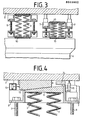
- a turbogenerator set 1 is set up on a foundation plate 2.
- the generally flexurally elastic foundation plate 2 is mounted on known elastic spring bodies 3, which in turn are arranged on foundation supports 4.
- a wave train 5 of the turboset is mounted in bearing blocks 6, which in turn are set up on the foundation plate 2.
- the spring bodies 3 correspond to the bending line the foundation plate 2 is biased before its construction for the expected operating loads. Then the foundation plate 2 is re-tensioned in a manner known per se, so that the shaft train 5 is expected to run smoothly during operation. Retensioning during later operation does not take place, but the messages that are required from time to time are carried out by aligning the bearing blocks 6 or the like. during maintenance, ie when the machine is at a standstill.
- separate adjusting devices 7 are attached in the spring bodies 3, which are for permanent residence and cause a change in the bearing conditions for the shaft train 5 by changing the load-bearing capacities of the spring bodies 3.
- hydraulic actuating devices 7 are arranged in the spring body shell 8, so that a uniform change in the load-bearing capacity of the spring body 3 takes place when the control devices 7 are actuated.
- Screws 9 are used for pre-tensioning before assembly.
- Intermediate layers 10 ensure a perfect, in particular non-slip, connection between spring body 3 and foundation plate 2 or foundation supports 4.
- the wedge connection 11, 12 is adjustable and is released by actuating the actuating device 7.
- An actuating cylinder 13 takes over the necessary adjustment of the wedge 12 in the wedge connection serving as a blocking device.
- the wedges carry the foundation plate, whereby the actuating device 7 is relieved.
- a measuring device 14 is used to record the state or the position of the wedge 12.
- Another measuring device 15 is used to record the state or the size of the change in the load capacity of the spring body 3.
- the corresponding data of the status indicators 14 and 15 enable the use of known principles of process calculation a constant automatic notification of the wave train 5 depending on the occurring changes in state.
- a corresponding control loop is indicated in FIG. 4.
- the bearing blocks 6 are equipped with vibration transmitters 16, which report deviations via channels 17, for example, from the smooth running of the wave train 5, to a process computer 18, which in turn sends corresponding commands via channels 19 to the position transmitters or Relays 20 forwards to cause the actuators 7 to act in the manner described above.
Landscapes
- Engineering & Computer Science (AREA)
- General Engineering & Computer Science (AREA)
- Mechanical Engineering (AREA)
- Physics & Mathematics (AREA)
- Acoustics & Sound (AREA)
- Aviation & Aerospace Engineering (AREA)
- Vibration Prevention Devices (AREA)
- Other Liquid Machine Or Engine Such As Wave Power Use (AREA)
Applications Claiming Priority (2)
| Application Number | Priority Date | Filing Date | Title |
|---|---|---|---|
| DE3200815 | 1982-01-11 | ||
| DE3200815A DE3200815C2 (de) | 1982-01-11 | 1982-01-11 | Verfahren zum Ausrichten der Wellen eines Wellenzuges |
Publications (3)
| Publication Number | Publication Date |
|---|---|
| EP0083902A2 true EP0083902A2 (fr) | 1983-07-20 |
| EP0083902A3 EP0083902A3 (en) | 1986-02-19 |
| EP0083902B1 EP0083902B1 (fr) | 1988-07-27 |
Family
ID=6152973
Family Applications (1)
| Application Number | Title | Priority Date | Filing Date |
|---|---|---|---|
| EP82730115A Expired EP0083902B1 (fr) | 1982-01-11 | 1982-09-03 | Procédé pour l'alignement des arbres de machines montées de façon élastique |
Country Status (3)
| Country | Link |
|---|---|
| EP (1) | EP0083902B1 (fr) |
| JP (2) | JPS58121336A (fr) |
| DE (1) | DE3200815C2 (fr) |
Cited By (4)
| Publication number | Priority date | Publication date | Assignee | Title |
|---|---|---|---|---|
| EP0294732A3 (fr) * | 1987-06-08 | 1989-07-12 | Vibro Dynamics Corporation | Système du type à assistance pour le montage d'équipement |
| US4930741A (en) * | 1987-06-08 | 1990-06-05 | Vibro Dynamics Corporation | Power assisted equipment mounting system |
| WO2018192524A1 (fr) * | 2017-04-22 | 2018-10-25 | 冯煜珵 | Système de support pour ensemble turbogénérateur |
| EP4345358A1 (fr) * | 2022-09-30 | 2024-04-03 | Etel S.A. | Système anti-vibration actif pour un système de mouvement de précision |
Families Citing this family (11)
| Publication number | Priority date | Publication date | Assignee | Title |
|---|---|---|---|---|
| JPH0612136B2 (ja) * | 1984-11-07 | 1994-02-16 | 日野自動車工業株式会社 | キャブの弾性支持装置 |
| US4860507A (en) * | 1988-07-15 | 1989-08-29 | Garza Tamez Federico | Structure stabilization system |
| JPH0389046A (ja) * | 1989-08-30 | 1991-04-15 | Ohbayashi Corp | 免震装置 |
| JP3182158B2 (ja) * | 1991-02-25 | 2001-07-03 | キヤノン株式会社 | 露光装置用のステージ支持装置 |
| US5797227A (en) * | 1996-04-09 | 1998-08-25 | Garza-Tamez; Federico | Structure stabilization system |
| US6115972A (en) * | 1996-04-09 | 2000-09-12 | Tamez; Federico Garza | Structure stabilization system |
| JP3936621B2 (ja) * | 2002-04-30 | 2007-06-27 | 隆夫 ▲高▼松 | 遊隙充填引張型制震構造 |
| JP5504075B2 (ja) * | 2010-07-06 | 2014-05-28 | 東洋ゴム工業株式会社 | ストッパ付空気ばね |
| RU2496036C2 (ru) * | 2011-12-29 | 2013-10-20 | Федеральное государственное бюджетное образовательное учреждение высшего профессионального образования "Московский государственный технический университет имени Н.Э. Баумана" (МГТУ им. Н.Э. Баумана) | Способ размещения виброизолирующих опор под рамой технологического агрегата |
| JP5897383B2 (ja) * | 2012-04-10 | 2016-03-30 | 学校法人上智学院 | 結合構造体の静剛性を維持又は向上させつつ動剛性及び減衰能を向上させる方法 |
| EP2711504A1 (fr) * | 2012-09-19 | 2014-03-26 | Siemens Aktiengesellschaft | Dispositif destiné au pontage d'un jeu |
Family Cites Families (7)
| Publication number | Priority date | Publication date | Assignee | Title |
|---|---|---|---|---|
| DE727537C (de) * | 1939-06-09 | 1942-11-05 | Maschf Augsburg Nuernberg Ag | Bettung fuer grosse liegende mehrzylindrige Kolbenmaschinen |
| GB1125171A (en) * | 1965-04-02 | 1968-08-28 | Ass Elect Ind | Improvements in or relating to steam turbine installations |
| CA797085A (en) * | 1966-05-26 | 1968-10-22 | Westinghouse Electric Corporation | Adjustable flexible mounting for rotating equipment |
| FR1571907A (fr) * | 1968-05-07 | 1969-06-20 | ||
| US4048842A (en) * | 1976-10-21 | 1977-09-20 | Korfund Dynamics Corporation | Shock and vibration control system for forging hammer |
| US4083433A (en) * | 1976-11-16 | 1978-04-11 | Westinghouse Electric Corporation | Active vibration damper with electrodynamic sensor and drive units |
| JPS5932644B2 (ja) * | 1979-07-13 | 1984-08-10 | 株式会社日立製作所 | 柔構造架台に対するタ−ビン発電機プラントの据付方法 |
-
1982
- 1982-01-11 DE DE3200815A patent/DE3200815C2/de not_active Expired
- 1982-09-03 EP EP82730115A patent/EP0083902B1/fr not_active Expired
- 1982-11-04 JP JP57193909A patent/JPS58121336A/ja active Granted
-
1987
- 1987-11-27 JP JP62299618A patent/JPS63172039A/ja active Pending
Cited By (5)
| Publication number | Priority date | Publication date | Assignee | Title |
|---|---|---|---|---|
| EP0294732A3 (fr) * | 1987-06-08 | 1989-07-12 | Vibro Dynamics Corporation | Système du type à assistance pour le montage d'équipement |
| US4930741A (en) * | 1987-06-08 | 1990-06-05 | Vibro Dynamics Corporation | Power assisted equipment mounting system |
| WO2018192524A1 (fr) * | 2017-04-22 | 2018-10-25 | 冯煜珵 | Système de support pour ensemble turbogénérateur |
| EP4345358A1 (fr) * | 2022-09-30 | 2024-04-03 | Etel S.A. | Système anti-vibration actif pour un système de mouvement de précision |
| US12203523B2 (en) | 2022-09-30 | 2025-01-21 | Etel S.A. | Active anti-vibration system for a precision motion system |
Also Published As
| Publication number | Publication date |
|---|---|
| EP0083902B1 (fr) | 1988-07-27 |
| JPS58121336A (ja) | 1983-07-19 |
| DE3200815A1 (de) | 1983-07-21 |
| EP0083902A3 (en) | 1986-02-19 |
| JPH0147662B2 (fr) | 1989-10-16 |
| JPS63172039A (ja) | 1988-07-15 |
| DE3200815C2 (de) | 1987-02-12 |
Similar Documents
| Publication | Publication Date | Title |
|---|---|---|
| EP0083902B1 (fr) | Procédé pour l'alignement des arbres de machines montées de façon élastique | |
| DE3141841C2 (fr) | ||
| EP0083903B1 (fr) | Elément de support élastique, en particulier élément ressort | |
| EP2013500B1 (fr) | Palier d'arrêt pour une machine électrique et machine électrique pourvue d'au moins un palier d'arrêt de ce type | |
| EP1580543A2 (fr) | Dispositif d'équilibrage pour compenser le déséquilibre des rotors des installations d'éoliennes | |
| AT520791B1 (de) | Verfahren zum Betreiben eines Stopfaggregats einer Gleisbaumaschine sowie Stopfvorrichtung zur Gleisbettverdichtung und Gleisbaumaschine | |
| EP0399296A2 (fr) | Justification automatique d'un laminoir universel après le changement des cylindres pour les profils neufs | |
| EP0690260B1 (fr) | Procédé de remplacement d'un élément de machine | |
| EP0483939B1 (fr) | Alignement de cylindres horizontaux | |
| EP0276364A2 (fr) | Ensemble de palier axial | |
| EP2768662A1 (fr) | Presse | |
| DE7508720U (de) | Einrichtung zur Änderung des Schwingungsverhaltens eines mindestens eine Welle aufweisenden, mehrfach gelagerten Wellenstranges | |
| DE2733793C2 (fr) | ||
| WO2021151578A1 (fr) | Dispositif et procédé de production d'énergie électrique dans une bande transporteuse d'un transporteur à bande | |
| EP0803720B1 (fr) | Station de mesure du balourd | |
| EP0232429A1 (fr) | Dispositif d'isolement contre les vibrations des machines et methode de demontage et montage | |
| EP0187784B1 (fr) | Dispositif d'essai pour elements en forme de barre, en particulier un segment d'ossature porteuse d'un ouvrage d'art | |
| DE2133234A1 (de) | Verfahren zur bestimmung des verhaltens eines in der radaufhaengung angeordneten stossdaempfers in den massen-federsystemen eines kraftfahrzeuges und vorrichtung zur durchfuehrung des verfahrens | |
| EP4179146B1 (fr) | Machine et procédé pour compacter un lit de ballast d'une voie | |
| DE3534660C2 (fr) | ||
| WO2020141082A1 (fr) | Installation d'ascenseur pourvue d'un dispositif de déplacement coulissant | |
| DE4422512C1 (de) | Gleitelement für Gehäuseauflagerungen | |
| EP4290205A2 (fr) | Dispositif de test pour composants soumis à des vibrations | |
| DE2713344A1 (de) | Einrichtung zur auswahl der walzensaetze fuer zwanzigwalzengerueste | |
| DE102006001626A1 (de) | Linearführungssystem an einer Betonsteinmaschine |
Legal Events
| Date | Code | Title | Description |
|---|---|---|---|
| PUAI | Public reference made under article 153(3) epc to a published international application that has entered the european phase |
Free format text: ORIGINAL CODE: 0009012 |
|
| AK | Designated contracting states |
Designated state(s): FR GB IT |
|
| PUAL | Search report despatched |
Free format text: ORIGINAL CODE: 0009013 |
|
| AK | Designated contracting states |
Designated state(s): FR GB IT |
|
| 17P | Request for examination filed |
Effective date: 19860219 |
|
| 17Q | First examination report despatched |
Effective date: 19870225 |
|
| GRAA | (expected) grant |
Free format text: ORIGINAL CODE: 0009210 |
|
| AK | Designated contracting states |
Kind code of ref document: B1 Designated state(s): FR GB IT |
|
| ET | Fr: translation filed | ||
| ITF | It: translation for a ep patent filed | ||
| GBT | Gb: translation of ep patent filed (gb section 77(6)(a)/1977) | ||
| PLBE | No opposition filed within time limit |
Free format text: ORIGINAL CODE: 0009261 |
|
| STAA | Information on the status of an ep patent application or granted ep patent |
Free format text: STATUS: NO OPPOSITION FILED WITHIN TIME LIMIT |
|
| 26N | No opposition filed | ||
| PGFP | Annual fee paid to national office [announced via postgrant information from national office to epo] |
Ref country code: GB Payment date: 19920908 Year of fee payment: 11 |
|
| PGFP | Annual fee paid to national office [announced via postgrant information from national office to epo] |
Ref country code: FR Payment date: 19920909 Year of fee payment: 11 |
|
| ITTA | It: last paid annual fee | ||
| PG25 | Lapsed in a contracting state [announced via postgrant information from national office to epo] |
Ref country code: GB Effective date: 19930903 |
|
| GBPC | Gb: european patent ceased through non-payment of renewal fee |
Effective date: 19930903 |
|
| PG25 | Lapsed in a contracting state [announced via postgrant information from national office to epo] |
Ref country code: FR Free format text: LAPSE BECAUSE OF NON-PAYMENT OF DUE FEES Effective date: 19940531 |
|
| REG | Reference to a national code |
Ref country code: FR Ref legal event code: ST |