EP0082748B1 - Machine de rectification plane frontale notamment pour rectifier les extrémités de fibres optiques - Google Patents
Machine de rectification plane frontale notamment pour rectifier les extrémités de fibres optiques Download PDFInfo
- Publication number
- EP0082748B1 EP0082748B1 EP82402230A EP82402230A EP0082748B1 EP 0082748 B1 EP0082748 B1 EP 0082748B1 EP 82402230 A EP82402230 A EP 82402230A EP 82402230 A EP82402230 A EP 82402230A EP 0082748 B1 EP0082748 B1 EP 0082748B1
- Authority
- EP
- European Patent Office
- Prior art keywords
- machine according
- slide
- spindle
- workpiece holder
- abrasive wheel
- Prior art date
- Legal status (The legal status is an assumption and is not a legal conclusion. Google has not performed a legal analysis and makes no representation as to the accuracy of the status listed.)
- Expired
Links
- 239000013307 optical fiber Substances 0.000 claims description 20
- 238000013519 translation Methods 0.000 claims description 7
- 230000000670 limiting effect Effects 0.000 claims description 3
- 239000000835 fiber Substances 0.000 description 38
- 239000000969 carrier Substances 0.000 description 15
- 238000000034 method Methods 0.000 description 6
- 238000005520 cutting process Methods 0.000 description 5
- XLYOFNOQVPJJNP-UHFFFAOYSA-N water Substances O XLYOFNOQVPJJNP-UHFFFAOYSA-N 0.000 description 4
- 239000006061 abrasive grain Substances 0.000 description 3
- 239000003795 chemical substances by application Substances 0.000 description 3
- 235000019589 hardness Nutrition 0.000 description 3
- 238000006748 scratching Methods 0.000 description 3
- 230000002393 scratching effect Effects 0.000 description 3
- 239000000853 adhesive Substances 0.000 description 2
- 230000001070 adhesive effect Effects 0.000 description 2
- 230000005540 biological transmission Effects 0.000 description 2
- 239000011449 brick Substances 0.000 description 2
- 229910003460 diamond Inorganic materials 0.000 description 2
- 239000010432 diamond Substances 0.000 description 2
- 229920001971 elastomer Polymers 0.000 description 2
- 230000004927 fusion Effects 0.000 description 2
- 230000036961 partial effect Effects 0.000 description 2
- 230000001681 protective effect Effects 0.000 description 2
- 238000007789 sealing Methods 0.000 description 2
- 241000669069 Chrysomphalus aonidum Species 0.000 description 1
- 241000826860 Trapezium Species 0.000 description 1
- 239000003082 abrasive agent Substances 0.000 description 1
- 230000001154 acute effect Effects 0.000 description 1
- 238000004026 adhesive bonding Methods 0.000 description 1
- 238000013459 approach Methods 0.000 description 1
- 239000002131 composite material Substances 0.000 description 1
- 230000006835 compression Effects 0.000 description 1
- 238000007906 compression Methods 0.000 description 1
- 238000006073 displacement reaction Methods 0.000 description 1
- 239000000806 elastomer Substances 0.000 description 1
- 230000005484 gravity Effects 0.000 description 1
- 230000000977 initiatory effect Effects 0.000 description 1
- 238000003780 insertion Methods 0.000 description 1
- 230000037431 insertion Effects 0.000 description 1
- 238000005304 joining Methods 0.000 description 1
- 239000010985 leather Substances 0.000 description 1
- 238000003754 machining Methods 0.000 description 1
- 239000000463 material Substances 0.000 description 1
- 230000003287 optical effect Effects 0.000 description 1
- 210000000056 organ Anatomy 0.000 description 1
- 230000002093 peripheral effect Effects 0.000 description 1
- 238000005498 polishing Methods 0.000 description 1
- 238000012545 processing Methods 0.000 description 1
- 230000000750 progressive effect Effects 0.000 description 1
- 230000002829 reductive effect Effects 0.000 description 1
- 230000002441 reversible effect Effects 0.000 description 1
- 238000005096 rolling process Methods 0.000 description 1
- 125000006850 spacer group Chemical group 0.000 description 1
- 239000007921 spray Substances 0.000 description 1
- 239000000758 substrate Substances 0.000 description 1
- 238000003466 welding Methods 0.000 description 1
Images


Classifications
-
- B—PERFORMING OPERATIONS; TRANSPORTING
- B24—GRINDING; POLISHING
- B24B—MACHINES, DEVICES, OR PROCESSES FOR GRINDING OR POLISHING; DRESSING OR CONDITIONING OF ABRADING SURFACES; FEEDING OF GRINDING, POLISHING, OR LAPPING AGENTS
- B24B19/00—Single-purpose machines or devices for particular grinding operations not covered by any other main group
- B24B19/22—Single-purpose machines or devices for particular grinding operations not covered by any other main group characterised by a special design with respect to properties of the material of non-metallic articles to be ground
- B24B19/226—Single-purpose machines or devices for particular grinding operations not covered by any other main group characterised by a special design with respect to properties of the material of non-metallic articles to be ground of the ends of optical fibres
-
- G—PHYSICS
- G02—OPTICS
- G02B—OPTICAL ELEMENTS, SYSTEMS OR APPARATUS
- G02B6/00—Light guides; Structural details of arrangements comprising light guides and other optical elements, e.g. couplings
- G02B6/24—Coupling light guides
- G02B6/36—Mechanical coupling means
- G02B6/38—Mechanical coupling means having fibre to fibre mating means
- G02B6/3807—Dismountable connectors, i.e. comprising plugs
- G02B6/3873—Connectors using guide surfaces for aligning ferrule ends, e.g. tubes, sleeves, V-grooves, rods, pins, balls
- G02B6/3885—Multicore or multichannel optical connectors, i.e. one single ferrule containing more than one fibre, e.g. ribbon type
-
- G—PHYSICS
- G02—OPTICS
- G02B—OPTICAL ELEMENTS, SYSTEMS OR APPARATUS
- G02B6/00—Light guides; Structural details of arrangements comprising light guides and other optical elements, e.g. couplings
- G02B6/24—Coupling light guides
- G02B6/25—Preparing the ends of light guides for coupling, e.g. cutting
-
- G—PHYSICS
- G02—OPTICS
- G02B—OPTICAL ELEMENTS, SYSTEMS OR APPARATUS
- G02B6/00—Light guides; Structural details of arrangements comprising light guides and other optical elements, e.g. couplings
- G02B6/24—Coupling light guides
- G02B6/36—Mechanical coupling means
- G02B6/38—Mechanical coupling means having fibre to fibre mating means
- G02B6/3807—Dismountable connectors, i.e. comprising plugs
- G02B6/3833—Details of mounting fibres in ferrules; Assembly methods; Manufacture
- G02B6/3863—Details of mounting fibres in ferrules; Assembly methods; Manufacture fabricated by using polishing techniques
Definitions
- the present invention relates to a front plane grinding machine comprising a grinding wheel, a grinding spindle movable parallel to its axis, means for rotating the spindle, a workpiece carrier and means for rotating the workpiece carrier around of an axis parallel to that of the grinding wheel spindle and in a circular sector at the ends of which workpieces to be ground supported by the workpiece carrier are respectively in front and by side of the working front face of the grinding wheel.
- the invention relates more particularly to such a grinding machine for grinding the faces of very small parts, and in particular of two parts to abut, such as the faces at the ends of optical fibers mounted on connection supports for two multi-fiber cables.
- the first two methods can generally be used when the fibers have to be connected one by one.
- the third method relates more particularly to the subject of the invention.
- several fibers have to be connected, such as the numerous fibers of two multi-fiber cables, it is advantageous, in particular with a view to reducing the individual handling for each pair of fibers and consequently the duration of the connection, to treat all the fibers at the same time.
- This simultaneous processing of the fibers is carried out both for stripping, positioning or bonding operations, as well as for the operation which consists in simultaneously erecting all the end faces of the fibers so as to locate them all on the same plane.
- Front planar grinding machines as defined in the preamble of claim 1 are described in patent documents US-A-3,299,579 and GB-A-441,022.
- the workpiece carrier is a rotating arm comprising a cavity for guiding a workpiece.
- the means for alternately rotating the workpiece carrier are of the connecting rod-crank type.
- Two superimposed and coaxial circular grinding wheels are provided for simultaneously grinding the two faces of a part.
- Each grinding wheel spindle with its rotational drive motor is manually slidable along vertical columns, parallel to its axis, by means of a flywheel in order to adjust the spacing between the working faces of the grinding wheels.
- Each grinding wheel is made up of three concentric abrasive portions having different grades or hardness so that the part, when it passes between the grinding wheels from their periphery towards their center, is first deburred and then more and more finely ground.
- the cavity of the workpiece carrier receives the lower part of a stack of such parts in a column when the workpiece holder is on the side of the grinding wheels, then the workpiece carrier turns towards the center of the grinding wheels in view gradually rectify the two faces of the part and finally the rectified part falls into a column coaxial with the spindle carrying the lower grinding wheel towards a conveyor.
- the workpiece is not really carried by the workpiece carrier arm but driven by it and guided during this rotation by a guide and then by the faces opposite the grinding wheels.
- the workpiece can even turn on itself when it is rectified by peripheral and intermediate abrasive portions.
- the workpiece carrier rotates from the center of the grinding wheels to the workpiece feed column, without "carrying" workpieces.
- the workpiece carrier is also driven in alternating rotation between the periphery and the center of two coaxial grinding wheels and superimposed by a system of connecting rod, crank and eccentric cam.
- the workpiece holder is a vice for enclosing one or more pieces such as bricks.
- the workpieces are adjusted during the two rotations in the opposite direction of the workpiece carrier.
- the parts are fragile, such as optical fibers, the scratching of the faces at the ends of the fibers gives a junction between butted fibers having a considerable insertion loss for the transmission of optical signals.
- the main object of the present invention is to remedy the above drawbacks.
- the workpieces must be ground during the rotation of the workpiece carrier, from the side towards the center of the grinding wheel, and must no longer be in contact with the wheel during the rotation of the workpiece carrier in reverse order '' avoid scratching the rectified parts.
- Such scratching must be avoided in particular when the working front face of the grinding wheel comprises concentric circular plates having different structures and / or grades.
- a frontal plane grinding machine is characterized according to claim 1.
- the rotation of the workpiece carrier towards the front face of the grinding wheel constitutes the single workpiece grinding pass, and the return of the workpiece carrier by side of the grinding wheel, without any contact of the ground parts with the grinding wheel, allows the removal of the ground parts.
- such an alternative rotation of the workpiece carrier makes it possible to provide at least a second workpiece carrier which is driven by means of alternative rotation similar to those of the first workpiece carrier.
- the two workpiece carriers are diametrically opposite with respect to the center of the grinding wheel or, in general, arranged symmetrically with respect to the grinding wheel, and are driven according to opposite rotational movements. This makes it possible to simultaneously rectify the edges of two multi-fiber supports and the faces of the ends of the optical fibers fixed to the supports, and thus to obtain strictly coplanar faces.
- the duration of the grinding operation is further reduced by the fact that the speed of rotation of the workpiece holder in the direction of rotation from the side towards the front of the working front face of the grinding wheel , for which the parts are ground by the grinding wheel, is smaller than that of the workpiece holder in the opposite direction of rotation from the front towards the side of the working front face of the grinding wheel for which the ground parts are not in contact with the wheel.
- the means for driving the rotary and sliding members included in the frame of the machine are pneumatic motors in order to ensure great safety for the personnel using the machine.
- the invention provides means of forced air circulation in the frame of the machine in order to cool the electric motors but also to suppress any introduction of water by tight seals surrounding the rotating members emerging from the frame.
- the pressurized water is sprayed by an auxiliary device to cool the working front face of the grinding wheel and the parts being ground.
- a vice is attached to each workpiece holder.
- the grips of the jaws can be semi-cylindrical and suitable for trapping two parallel longitudinal grooves made in the support, said grooves serving to receive cylinders for aligning two identical multifiber supports and abutting their fibers.
- the vice and the grips of its jaws are adapted to the shape of the support or workpiece.
- the vice is provided with means for limiting the clamping force, such as a spring, so as not to damage the fiber supports made of relatively fragile material.
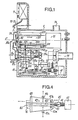
- the front planar grinding machine as shown in FIG. 1 comprises in front of the front face 10 of its frame 1, a cylindrical grinding wheel 2 and two oscillating workpiece carriers 3a and 3b.
- the grinding wheel 2 is clamped in a known manner to the external front end of a spindle 20 which is rotatably mounted in a bore 11 of the front face 10 of the frame through annular sealing means 110, such as O-rings. or flexible cuff of leather or rubber or the like.
- the grinding wheel spindle 20 extends in the upper internal part of the frame 1 along a horizontal longitudinal axis Z'Z and at its other end driven in rotation by motor means fixed to the frame 1.
- the motor means can be an electric motor, represented as a whole by block 21 in FIG. 1, or else a compressed air motor 22 associated with a pulley and belt drive system 23 as shown in FIG. 2.
- the grinding wheel 2 is enclosed in a protective cover 24 which is fixed on the front face 10 of the frame and in which two openings are made in the arc sector for the free passage of the upper oscillating ends 30a, 30b of the two workpiece carriers 3a, 3b which are intended to support the parts to be rectified.
- the workpiece carriers 3a, 3b are fixed to the external ends of two longitudinal shafts 31a, 31b which pass through two bores 12a, 12b of the front face 10 of the frame through sealing sleeves 120a, 120b or the like.
- the axes of rotation of the shafts 31 a, 31 b are symmetrical with respect to the vertical diametrical axis Y'Y of the grinding wheel 2 at a distance from the latter substantially equal to the mean radius of the working front surface of the grinding wheel 2.
- the distance between the horizontal plane containing the axes of the shafts 31a, 31b and the horizontal diametrical axis X'X of the grinding wheel 2 determines the length of the workpiece carriers or oscillating levers 3a, 3b so that the workpieces to be ground fixed at the ends 30a , 30b are substantially in the horizontal plane having for trace the axis X'X.
- the sealed bores 12a and 12b are extended longitudinally inside the frame by two composite bores 13a, 13b formed in two bosses 14a, 14b internal to the frame 1.
- Two sets of roller bearings 15a, 15b for example conical with symmetrical inclinations are embedded in the bores 13a, 13b and form bearings for the shafts 31a, 31b.
- Each internal end of a shaft 31a, 31b is secured by transverse keying or the like, indicated at 32a, 32b, of the first upper end of a slender, substantially vertical member 40a, 40b.
- Each pair composed of a shaft 31a, 31b and a member 40a, 40b is held stationary in longitudinal translation by means of two stops supported by the shaft.
- One of these stops 33a, 33b comprises a stack of elastic washers with backlash and is disposed against one of the bearings 15a, 15b while against the other bearing is applied a front shoulder of the shaft.
- the other stop 34a, 34b is arranged at the internal end of the shaft 31a, 31b against the rear upper end of the member 40a, 40b and is a locking stop with stop ring and nut.
- a roller 41 a, 41 b is mounted in substantially vertical rotation at the second lower end of the member 40a, 40b.
- the rollers 41 a and 41 b can roll against two respective ramps 42a, 42b which form the inclined sides of a central longitudinal slide 42 which has a horizontal profile in an isosceles trapezoid.
- the inclined sides 42a and 42b form an acute angle with respect to the longitudinal direction ZZ and therefore with respect to the axes of the rotating shafts 31 a and 31 b.
- the ends of a helical spring 410 are fixed between the first and second ends of the members 40a and 40b. The spring 410 attracts the rollers 41 a and 41 b against the respective inclined sides 42a, 42b.
- the slide 42 has an underlying tongue 420 which slides in the longitudinal groove 160 of a slide 16 which is fixed on the internal face of the bottom of the frame 1.
- the sliding axis of the slide 42 is horizontal and in the vertical plane diametral Y'Y-ZZ of the grinding wheel 2.
- the vertical ramps 42a and 42b are symmetrical with respect to the sliding axis and diverge in the direction of the front face of the frame. When the slide 42 progressively moves away from the front face 10, the rollers 4la and 41b roll on the vertical ramps 42a and 42b and deviate from the sliding axis.
- the ends 30a and 30b of the workpiece carriers supporting the workpieces to be adjusted approach the axis of rotation ZZ of the grinding wheel 2 and describe two arcs of a circle which are diametrically and respectively opposite to those described by the members 40a and 40b moving away.
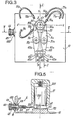
- the means for driving the slide 42 in slow rearward translation comprise, according to the embodiment illustrated in FIGS. 1 and 4, a connecting rod 43, a worm screw system 44 and nut 45, a means 46 for driving the nut 45 in translation perpendicular to the worm screw 44, and a motor 47.
- the two ends of the connecting rod 43 are rotatably mounted at the rear end of the slide 42 and on the nut 45, respectively.
- the declutching means 46 comprises an electromagnet, as shown in FIG. 1, or a jack, which allows the nut 45 to be reassembled or to mesh with the worm 44.
- the motor 47 can be an electric motor which is fixed on the internal face of the bottom of the frame 1 and which can cause according to the two directions of rotation the endless screw 44 around its longitudinal axis.
- the motor 47 can also be a pneumatic motor.
- the progressive retraction of the slide 42 towards the rear is achieved by the clutch of the nut 45 with the worm 44, which allows relatively slow rectification of the parts by the front face of the grinding wheel 2, compared to the rapid return rectified parts, as will be seen below.
- the adjustment of the speeds of the workpiece carriers 3a, 3b according to the two directions of rotation can be controlled by the variation of the speed of the motor 47.
- motor means are energized to drive in transla fast grinding wheel 2 parallel to its axis ZZ and backwards and to simultaneously drive the slide 42 in rapid forward translation and thus quickly move the grinding wheel away from the ends 30a, 30b of the workpiece carriers supporting the workpieces in front of the recoil of the wheel.
- These translation drive means are shown in FIG. 1 and comprise a pneumatic cylinder 50, the rod 51 of which is fixed for rotation on the lower arm of a lever 52.
- the articulation point 53 of the lever 52 is mounted for rotation about an axis parallel to the axis X ' X and secured to the frame between the pin 20 and the slide 42 above the internal bosses 14a and 14b; the upper arm of the lever is shorter than its lower arm and, consequently, the recoil stroke of the grinding wheel 2 is smaller compared to the advance of the slide 42 and the displacement of the ends 30a, 30b towards their initial positions.
- the lever 52 can oscillate in the vertical diametrical plane Y'Y - Z'Z of the grinding wheel 2, between the two internal bosses 14a and 14b.
- the end 520 of the lower arm of the lever 52 is intended to push an upper front protruding stop 421 of the slide 42 towards the front face 10.
- the end of the upper arm of the lever 52 is rotatably anchored at 521 to an underlying tongue 200 of the grinding wheel spindle 20 which slides in a longitudinal slide 17 made inside the frame, above the bosses 14a and 14b.
- the tongue 200 is in fact a part of the housing forming the spindle bearing. It is pushed against the front end of the slide 17 by a compression spring 201.
- the grinding machine comprises means 6 for adjusting the position of the front face of the grinding wheel 2 relative to the vertical surfaces of the workpieces to be ground, that is to say relative to the ends 30a, 30b of the workpiece carriers 3a, 3b.
- These means for adjusting the grinding pass depth 6 comprise a shim 60 having a horizontal section in a rectangular trapezium whose long side 61 is slightly inclined relative to the axis X'X and receives in abutment under the action of the spring.
- rear 201 the vertical front face with the same inclination 202 of the tongue 200 which slides in the upper slide 17.
- the other large side 62 of the wedge 60 is perpendicular to the axis ZZ and slides against the front vertical wall 170 of the slide 17.
- One end of the wedge 60 is extended by a threaded rod 63 which is screwed into the blind tapped hole 64 at the end of a nut 65.
- the knurled head 66 of the nut 65 is accessible on an external longitudinal wall of frame 1, as shown in FIG. 3.
- the smooth rod of the nut 65 between the head 66 and the blind hole 64 passes through an orifice 18 in the aforementioned wall of the frame 1 through an annular seal 67 and is stationary there axially by a conventional spacer by means of rings.
- the external stop ring 680 has a reference index.
- a vernier with a circular scale 69 is integral with the nut 65 and underlying the head 66.
- the rotation of the head 66 and of the vernier 69 results in the translation of the wedge 60 and, consequently, of the adjustment of the front position of the tongue 200 which is in abutment against the large inclined side 61 of the shim 60 during the entire grinding pass.
- the rotation of the vernier 69 with respect to the reference index indicates the depth of pass of the grinding wheel 2.
- the adjustment means 6 ensure great fineness of adjustment of the depth of pass.
- no sliding of members is provided outside the machine and the seal is produced on a cylindrical part such as the smooth rod of the nut 65.
- auxiliary means can be provided to improve the rectification operation and are accessible by the control console 7.
- Two nozzles 70a and 70b are supported by stirrups fixed on the front face 10 of the frame and on the protective cover 24 and are pointed symmetri only towards the working front surface of the grinding wheel 2 at the level of the transverse axis X'X.
- the nozzles 70a and 70b are connected by flexible pipes 71a and 71b to a water sprinkler device under air pressure which sprays it during the rectification pass.
- Two small light spots 72a and 72b are supplied through flexible conductive cords 73a and 73b by a low voltage generator.
- the two spots 72a and 72b are fixed by stirrups on the external face of the cover 24 and illuminate the two diametrically opposite working places on the grinding wheel 2.
- a forced air circulation can be obtained inside the frame 1 by means of a fan 74 which is inserted in an air suction pipe. 75 crossing the rear face of the frame, and an air exhaust pipe 76 crossing the upper wall of the frame 1.
- the fan 74 cools the electric motors and creates an overpressure inside the frame 1 which eliminates any risk water introduction by nozzles 70a and 70b in case the joints such as 110, 120a and 120b are not completely sealed.
- the workpiece carrier 3 and the respective member 40 may not be diametrically opposed; for example, the member 40 can oscillate above the shaft 31 and laterally to the spindle 20, while the slider 42 slides in a slide above the spindle 20.
- the function of the slide 42 can be obtained by means of a rotary cam driven by a geared motor and a freewheel hub.
- the frame of the machine forms a relatively small and light rectangular block, and easily portable.
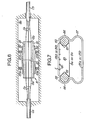
- the support 8 is an elongated parallelepipedic substrate of which one of the large faces is provided, over its entire length, with parallel longitudinal grooves in vee 80 which are adapted to each receive the stripped ends of two fibers to abut Fa and Fb.
- the longitudinal edges of the support 8 have parallel grooves 61 which have a large cross section in vee or in blunt vee shape and which are intended to receive two calibrated cylinders 82 and to be clamped by vice jaws of the grinding machine.
- the support 8 also includes one or more small transverse grooves 83 which are in the transverse median plane of the support.
- the groove 83 serves as a breaking or sawing start to separate the support 8 into two identical semi-supports 8a and 8b.
- the fibers Fa and Fb are folded back into the grooves 81 of the respective half-supports 8a and 8b and are held there by a rapid-curing adhesive 84 and / or by application by means of half-plates 84a, 84b which are also grooved and obtained from a single plate 84 and which cover the half-supports.
- the ends of the fibers slightly exceed the transverse edges of the half-supports 8a and 8b corresponding to the groove 83.
- edges 83 of the half-supports 8a and 8b are then rectified together with that of the ends of the optical fibers Fa and Fb by means of the rectification machine according to the invention.
- Fig. 8 shows in detail, by way of example, the end 30b of a workpiece holder such as 3b which is adapted to receive one of the half-supports such as 8b.
- a notch having a large vertical side 35 which is practically parallel to the plane Y'Y-ZZ when the half-support is being rectified, as shown in FIG. 3.
- the notch is turned away from the grinding wheel 2.
- One, 90, of the jaws of a vice 9b has a vertical cross-section, which square is applied against the long side 35 of the notch and against the horizontal top of the end 30b, by means of a screw 91 screwed into a horizontal tapped hole in the end 30b.
- the other jaw 92 of the vice 9b is parallelepipedic and is pivotable about a horizontal articulation axis 93 which is parallel to the longitudinal axis ZZ and which is fixed to the lower part of the other jaw 90 in front of the corner of the end notch 30b.
- the vice 9b is provided with means for limiting the clamping force, such as a helical tension spring 94, which can be embedded in a jaw and pushed the grip thereof towards that of the other or, as illustrated, which can be anchored in two holes 95, 96 of jaw 90, 92 and which recalls the jaw 92 against the jaw 90.
- the withdrawal of the half-support 8b from the vice 9b is effected by taking the upper end of the jaw 92 in which a gripping notch 920 is formed, and by the pivoting of the jaw 92 around the articulation axis 93 against the tensile force exerted by the spring 94.
- the grips of the jaws can both be in the form of calibrated half-cylinders which have the same diameter as the calibrated cylinders 82 (FIG. 7).
- the ends of the fibers Fb and the cutting edge of each half-support 8b will thus be coplanar and perpendicular to the longitudinal axis of the half-support after rectification.
- These geometrical arrangements are ensured in particular by the grip of the grooves 81 by the semi-cylindrical grips of the jaws 90, 92 having a function similar to the positioning cylinders 82.
- the grip 97 of the grip 90 fixed at the end 30b overhangs a small notch 98 above which the vee grooves 81 of the half-support 8b are trapped by the semi-cylindrical grips of the jaws.
- the semi-cylindrical grip 99 of the pivotable jaw 92 can be a semi-cylindrical elastomer buffer embedded in the jaw 92 in order to distribute the clamping pressure and to absorb, together with the spring 94, the thrust forces due to the work of the grinding wheel during the grinding operation.
- the edges 83 of the half-supports 8a and 8b are aligned in a plane parallel to the front face of the grinding wheel by means of shims 980.
- the depth of cut of the grinding wheel is adjusted by the adjusting means 6 (Fig. 5).
- the rectification is carried out by bringing the ends 30a and 30b of the workpieces closer together.
- the grinding wheel 2 is a diamond disc of the straight bushel type (Fig. 9A) or, preferably, of the bushel type with a single conical bevel (Fig. 9B) or with a double conical bevel (Fig. 9C).
- the diamond grinding wheels with conical bevel (Fig. 9B and 9C) advantageously make it possible to start the machining operation by cutting at least the ends of the optical fibers Fa, Fb beyond the sawing edges of the half-supports 8a, 8b.
- the structure of the grinding wheel that is to say the spacing coefficient of its abrasive grains or the concentration thereof, and its hardness, that is to say the grade or strength cohesion retaining the abrasive grains, can be staggered over several concentric areas of the working front face of the grinding wheel.
- the staggering of the pads is such that, from the periphery of the grinding wheel, the structures of the abrasive pads are more and more closed or tight, the sizes of their abrasive grains decrease and their hardnesses are increasingly higher.
- Such a staggering of the abrasives achieves in a single pass or approximation of the ends 30a and 30b of the workpiece carriers, the roughing and the finishing through. intermediate phases of rectification of the cutting edges of the half-supports 8a and 8b and of the ends of the optical fibers Fa and Fb.
- the rectified edges of the half-supports are abutted and aligned in pairs.
- they are coated with an index-matching agent which has a refractive index corresponding to that of the core of the optical fibers, in order to reduce the losses due to reflections at the ends of the fibers.
- the ends of the fibers Fa and Fb of the two half-supports 8a and 8b are aligned by the application of the two calibrated alignment cylinders 82 in the longitudinal V-shaped grooves 81, as shown in FIGS. 6 and 7.
- This application is exerted by at least two flexible fasteners or clips 85a and 85b in the form of a horseshoe with a flat or curved handle.
- the two angled S-shaped ends 86 of a clip 85 enclose the opposite peripheries of the cylinders 82.
- the handles 87 of these fasteners can be in contact with the internal walls of the housing 88 of the connection device in order to absorb any vibration, particularly radial, on the junction of the optical fibers both during connection and laying of cables in the field as after these.
- the fasteners can be double horseshoe rings, the parts of which are symmetrical with respect to the median horizontal plane of the half-supports are similar to the fastener shown in FIG. 7.
- the flat half-supports 8a and 8b may be cylindrical half-supports having vee alignment grooves, such as 81, diametrically opposite and small grooves 80 equally distributed circularly above and below the grooves d 'alignment.
- half-covering plates such as 84a, 84b are used, they are constituted by two semi-cylindrical half-shells. The latter can be replaced by a layer of fast-curing adhesive, equivalent to layer 84 having a thickness substantially equal to that of the half-plates 84a and 84b.
Landscapes
- Physics & Mathematics (AREA)
- Engineering & Computer Science (AREA)
- Mechanical Engineering (AREA)
- General Physics & Mathematics (AREA)
- Optics & Photonics (AREA)
- Grinding And Polishing Of Tertiary Curved Surfaces And Surfaces With Complex Shapes (AREA)
Applications Claiming Priority (2)
| Application Number | Priority Date | Filing Date | Title |
|---|---|---|---|
| FR8123721A FR2518443A1 (fr) | 1981-12-18 | 1981-12-18 | Machine de rectification plane frontale et son utilisation pour rectifier les extremites de fibres optiques |
| FR8123721 | 1981-12-18 |
Publications (2)
| Publication Number | Publication Date |
|---|---|
| EP0082748A1 EP0082748A1 (fr) | 1983-06-29 |
| EP0082748B1 true EP0082748B1 (fr) | 1986-09-10 |
Family
ID=9265176
Family Applications (1)
| Application Number | Title | Priority Date | Filing Date |
|---|---|---|---|
| EP82402230A Expired EP0082748B1 (fr) | 1981-12-18 | 1982-12-06 | Machine de rectification plane frontale notamment pour rectifier les extrémités de fibres optiques |
Country Status (4)
| Country | Link |
|---|---|
| US (1) | US4538383A (enExample) |
| EP (1) | EP0082748B1 (enExample) |
| DE (1) | DE3273244D1 (enExample) |
| FR (1) | FR2518443A1 (enExample) |
Families Citing this family (11)
| Publication number | Priority date | Publication date | Assignee | Title |
|---|---|---|---|---|
| KR910014726A (ko) * | 1990-01-19 | 1991-08-31 | 조오지 더블유.우드 | 광스위치 조립방법 |
| US5037176A (en) * | 1990-01-19 | 1991-08-06 | Adc Telecommunications, Inc. | Optical switch with reduced reflection |
| US6629877B2 (en) | 2001-02-21 | 2003-10-07 | Leon A. Cerniway | Precision glass grinding |
| US20030182015A1 (en) * | 2002-03-19 | 2003-09-25 | Domaille Michael D. | Polisher |
| AU2003302813A1 (en) * | 2002-12-10 | 2004-06-30 | Schleuniger Holding Ag | Separating device for cutting cables, especially optical waveguides |
| CN100465713C (zh) * | 2005-06-20 | 2009-03-04 | 乐金显示有限公司 | 液晶显示设备用研磨机轮和用其制造液晶显示设备的方法 |
| ITMI20131281A1 (it) | 2013-07-31 | 2015-02-01 | Pirelli | Metodo ed apparato per alimentare una pluralita' di fasce battistrada in un processo per confezionare pneumatici per ruote di veicoli |
| CN104858749A (zh) * | 2014-07-13 | 2015-08-26 | 杜正阔 | 一种可用于复合材料车削加工的数控机床 |
| CN114918792B (zh) * | 2022-05-31 | 2023-07-18 | 浙江博得新材料科技有限公司 | 一种多角度调节功能具有清洁机构的塑料产品用打磨装置 |
| US20240123562A1 (en) * | 2022-10-13 | 2024-04-18 | viaPhoton, Inc. | Fiber polishing system |
| CN116197781B (zh) * | 2023-05-04 | 2023-07-04 | 内蒙古工业大学 | 一种弧形新材料的内弧形面打磨机床 |
Citations (1)
| Publication number | Priority date | Publication date | Assignee | Title |
|---|---|---|---|---|
| US3299579A (en) * | 1964-01-17 | 1967-01-24 | Heald Machine Co | Grinding machine |
Family Cites Families (18)
| Publication number | Priority date | Publication date | Assignee | Title |
|---|---|---|---|---|
| DE565025C (de) * | 1932-11-25 | Franz Dohnalek | Flaechenschleifmaschine, insbesondere zum Ebenschleifen der Endflaechen von Schraubenfedern | |
| US1402700A (en) * | 1922-01-03 | A cobpobatiokt of | ||
| GB590952A (en) * | 1945-04-21 | 1947-08-01 | Heath Spring & Notion Company | Improvements relating to machines for grinding the ends of coiled springs |
| US653531A (en) * | 1899-07-10 | 1900-07-10 | Nat Carbon Co | Machine for grinding carbon diaphragms. |
| CH96860A (de) * | 1922-07-15 | 1922-11-16 | Sperisen Franz | Stoffhalter. |
| US1640715A (en) * | 1925-11-28 | 1927-08-30 | Allen W Morton | Face-grinding machine |
| US1966194A (en) * | 1930-03-10 | 1934-07-10 | Bunting Brass And Bronzc Compa | Grinding machine |
| GB441022A (en) * | 1934-07-13 | 1936-01-10 | Walter Harold Sabine Junior | Improvements in and relating to abrasive machinery |
| GB505891A (en) * | 1937-10-13 | 1939-05-15 | F E Rowland And Company Ltd | Improvements in and relating to grinding, polishing and like machines |
| US2424448A (en) * | 1943-08-06 | 1947-07-22 | Gardner Machine Co | Grinding machine |
| US2392819A (en) * | 1944-01-24 | 1946-01-15 | Gear Grinding Company | Gear grinding machine |
| US2799125A (en) * | 1952-02-18 | 1957-07-16 | Allen A Dicke | Rotary knife grinders |
| US2885832A (en) * | 1956-07-20 | 1959-05-12 | Rca Corp | Art of forming surfaces of peculiar contours |
| DE1170277B (de) * | 1958-03-14 | 1964-05-14 | Karl Hack | Federendenschleifmaschine |
| US3322423A (en) * | 1964-06-24 | 1967-05-30 | Popow Anatoliy | Vise jaw cover plate |
| US3653160A (en) * | 1969-04-23 | 1972-04-04 | Ind Micronics Inc | Lapping machine and method |
| US4384431A (en) * | 1980-03-31 | 1983-05-24 | Western Electric Company, Inc. | Methods of and apparatus for preparing an end portion of a lightguide fiber |
| US4335873A (en) * | 1980-05-21 | 1982-06-22 | C. J. Edwards Company | Toggle bolt clamp |
-
1981
- 1981-12-18 FR FR8123721A patent/FR2518443A1/fr active Granted
-
1982
- 1982-12-06 DE DE8282402230T patent/DE3273244D1/de not_active Expired
- 1982-12-06 EP EP82402230A patent/EP0082748B1/fr not_active Expired
- 1982-12-09 US US06/448,070 patent/US4538383A/en not_active Expired - Fee Related
Patent Citations (1)
| Publication number | Priority date | Publication date | Assignee | Title |
|---|---|---|---|---|
| US3299579A (en) * | 1964-01-17 | 1967-01-24 | Heald Machine Co | Grinding machine |
Also Published As
| Publication number | Publication date |
|---|---|
| FR2518443A1 (fr) | 1983-06-24 |
| US4538383A (en) | 1985-09-03 |
| DE3273244D1 (en) | 1986-10-16 |
| FR2518443B1 (enExample) | 1984-10-26 |
| EP0082748A1 (fr) | 1983-06-29 |
Similar Documents
| Publication | Publication Date | Title |
|---|---|---|
| EP0082748B1 (fr) | Machine de rectification plane frontale notamment pour rectifier les extrémités de fibres optiques | |
| EP0640435B1 (fr) | Machine à meuler | |
| FR2667530A1 (fr) | Procede et appareil de rectification des manetons de vilebrequin. | |
| EP1606079A1 (fr) | Machine de meulage de verres optiques | |
| FR2464798A1 (fr) | Machine de conditionnement pour brosser la face terminale d'un materiau metallique | |
| FR2947472A1 (fr) | Procede et dispositif d'usinage d'une piece par abrasion | |
| EP0456590A1 (fr) | Dispositif de rectification de la tête d'une soupape, notamment d'un moteur à combustion interne | |
| FR2986172A1 (fr) | Tete d'usinage pour centre d'usinage multiaxial | |
| EP0820837A1 (fr) | Machine de meulage de verres optiques | |
| FR2567057A1 (fr) | Appareil de meulage de plaques de verre | |
| EP2656969B1 (fr) | Poste de rectification pour usiner au moins un bloc de béton à coller. | |
| FR2972382A1 (fr) | Machine de meulage de verres optiques et procede de meulage associe | |
| EP0196941B1 (fr) | Dispositif de surfaçage et de polissage du chant vertical d'une pierre ou d'un élément préfabriqué massif | |
| EP0073725A1 (fr) | Machine pour la mise en état et/ou l'entretien des sols | |
| EP0038763B1 (fr) | Machine pour ponçage des angles arrondis | |
| EP2598288B1 (fr) | Dispositif d'avivage de meule de travail et son utilisation dans une rectifieuse sans centre de pastilles de combustible nucleaire | |
| FR2513556A1 (fr) | Procede et appareil d'ebarbage automatique de pieces mecaniques, a l'aide d'une brosse rotative | |
| FR2629448A1 (fr) | Appareillage pour decouper une piece en un materiau du type verre ou ceramique le long d'une ligne incisee | |
| EP0506533B1 (fr) | Appareil de sciage | |
| FR2541603A1 (fr) | Appareil a cintrer | |
| EP0035939B1 (fr) | Machine à outil rotatif pour les travaux de reproduction ou de finition | |
| FR2694715A1 (fr) | Procédé et appareil de rectification des manetons de villebrequin. | |
| BE838121R (fr) | Machine a chanfreiner les bords de plaques de verre | |
| CA1206756A (en) | Front surface grinding machine | |
| FR3012358A1 (fr) | Ensemble pour usiner au moins un bloc de beton a coller et poste de rectification comprenant un tel ensemble |
Legal Events
| Date | Code | Title | Description |
|---|---|---|---|
| PUAI | Public reference made under article 153(3) epc to a published international application that has entered the european phase |
Free format text: ORIGINAL CODE: 0009012 |
|
| AK | Designated contracting states |
Designated state(s): BE CH DE GB IT LI NL SE |
|
| 17P | Request for examination filed |
Effective date: 19830812 |
|
| GRAA | (expected) grant |
Free format text: ORIGINAL CODE: 0009210 |
|
| AK | Designated contracting states |
Kind code of ref document: B1 Designated state(s): BE CH DE GB IT LI NL SE |
|
| REF | Corresponds to: |
Ref document number: 3273244 Country of ref document: DE Date of ref document: 19861016 |
|
| ITF | It: translation for a ep patent filed | ||
| PLBE | No opposition filed within time limit |
Free format text: ORIGINAL CODE: 0009261 |
|
| STAA | Information on the status of an ep patent application or granted ep patent |
Free format text: STATUS: NO OPPOSITION FILED WITHIN TIME LIMIT |
|
| 26N | No opposition filed | ||
| PGFP | Annual fee paid to national office [announced via postgrant information from national office to epo] |
Ref country code: NL Payment date: 19871231 Year of fee payment: 6 |
|
| PG25 | Lapsed in a contracting state [announced via postgrant information from national office to epo] |
Ref country code: GB Effective date: 19881206 |
|
| PG25 | Lapsed in a contracting state [announced via postgrant information from national office to epo] |
Ref country code: LI Effective date: 19881231 Ref country code: CH Effective date: 19881231 Ref country code: BE Effective date: 19881231 |
|
| BERE | Be: lapsed |
Owner name: SOC. INDUSTRIELLE DE LIAISONS ELECTRIQUES SILEC Effective date: 19881231 Owner name: S.A. DE TELECOMMUNICATIONS Effective date: 19881231 Owner name: L'ETAT FRANCAIS REPRESENTE PAR LE MINISTRE DES P. Effective date: 19881231 |
|
| PG25 | Lapsed in a contracting state [announced via postgrant information from national office to epo] |
Ref country code: NL Effective date: 19890701 |
|
| NLV4 | Nl: lapsed or anulled due to non-payment of the annual fee | ||
| GBPC | Gb: european patent ceased through non-payment of renewal fee | ||
| REG | Reference to a national code |
Ref country code: CH Ref legal event code: PL |
|
| PG25 | Lapsed in a contracting state [announced via postgrant information from national office to epo] |
Ref country code: DE Effective date: 19890901 |
|
| PG25 | Lapsed in a contracting state [announced via postgrant information from national office to epo] |
Ref country code: SE Effective date: 19891207 |
|
| EUG | Se: european patent has lapsed |
Ref document number: 82402230.5 Effective date: 19900104 |