EP0081842B1 - Drossel oder Transformator - Google Patents
Drossel oder Transformator Download PDFInfo
- Publication number
- EP0081842B1 EP0081842B1 EP19820111580 EP82111580A EP0081842B1 EP 0081842 B1 EP0081842 B1 EP 0081842B1 EP 19820111580 EP19820111580 EP 19820111580 EP 82111580 A EP82111580 A EP 82111580A EP 0081842 B1 EP0081842 B1 EP 0081842B1
- Authority
- EP
- European Patent Office
- Prior art keywords
- insulating material
- choke
- ribs
- shaped
- transformer according
- Prior art date
- Legal status (The legal status is an assumption and is not a legal conclusion. Google has not performed a legal analysis and makes no representation as to the accuracy of the status listed.)
- Expired
Links
- 239000011810 insulating material Substances 0.000 claims description 28
- 238000004804 winding Methods 0.000 claims description 21
- 238000010276 construction Methods 0.000 claims description 2
- 239000012774 insulation material Substances 0.000 claims 1
- 239000002184 metal Substances 0.000 description 4
- 229910052751 metal Inorganic materials 0.000 description 4
- RYGMFSIKBFXOCR-UHFFFAOYSA-N Copper Chemical compound [Cu] RYGMFSIKBFXOCR-UHFFFAOYSA-N 0.000 description 2
- 229910052802 copper Inorganic materials 0.000 description 2
- 239000010949 copper Substances 0.000 description 2
- 238000003780 insertion Methods 0.000 description 2
- 230000037431 insertion Effects 0.000 description 2
- 238000004519 manufacturing process Methods 0.000 description 2
- 239000011162 core material Substances 0.000 description 1
- 230000017525 heat dissipation Effects 0.000 description 1
- 230000001771 impaired effect Effects 0.000 description 1
- 238000002347 injection Methods 0.000 description 1
- 239000007924 injection Substances 0.000 description 1
- 239000000463 material Substances 0.000 description 1
- 230000001681 protective effect Effects 0.000 description 1
- 239000003351 stiffener Substances 0.000 description 1
- 238000003466 welding Methods 0.000 description 1
Images


Classifications
-
- H—ELECTRICITY
- H01—ELECTRIC ELEMENTS
- H01F—MAGNETS; INDUCTANCES; TRANSFORMERS; SELECTION OF MATERIALS FOR THEIR MAGNETIC PROPERTIES
- H01F27/00—Details of transformers or inductances, in general
- H01F27/24—Magnetic cores
- H01F27/26—Fastening parts of the core together; Fastening or mounting the core on casing or support
- H01F27/266—Fastening or mounting the core on casing or support
-
- H—ELECTRICITY
- H01—ELECTRIC ELEMENTS
- H01F—MAGNETS; INDUCTANCES; TRANSFORMERS; SELECTION OF MATERIALS FOR THEIR MAGNETIC PROPERTIES
- H01F27/00—Details of transformers or inductances, in general
- H01F27/28—Coils; Windings; Conductive connections
- H01F27/32—Insulating of coils, windings, or parts thereof
- H01F27/324—Insulation between coil and core, between different winding sections, around the coil; Other insulation structures
- H01F27/326—Insulation between coil and core, between different winding sections, around the coil; Other insulation structures specifically adapted for discharge lamp ballasts
-
- H—ELECTRICITY
- H01—ELECTRIC ELEMENTS
- H01F—MAGNETS; INDUCTANCES; TRANSFORMERS; SELECTION OF MATERIALS FOR THEIR MAGNETIC PROPERTIES
- H01F38/00—Adaptations of transformers or inductances for specific applications or functions
- H01F38/08—High-leakage transformers or inductances
- H01F38/10—Ballasts, e.g. for discharge lamps
Definitions
- the invention relates to a choke or transformer in a jacket design, in particular for use as a ballast for gas discharge lamps, with a core package layered in the longitudinal direction of the choke or transformer, which sits on a mounting plate, with a self-supporting coil which is placed on the core and insulated from it , whose winding overhangs protrude from the core package on both end faces and which are covered there in a contact-safe manner in each case by an insulating material part, which has an attachment that engages behind the winding overhangs from above, in cooperation with the mounting plate, the attachment protruding at least above the height of the coil into the space between the coil and core package .
- Such a choke is known for example from DE-A-2244158.
- the touch-proof covering of the winding overhangs takes place there by means of the insulating material parts placed on the winding overhangs in the form of insulating material housings, which cover the winding overhangs of the coil by means of a rear wall, an end wall and three walls on the circumference and are accordingly constructed in a material-consuming and complicated manner.
- a choke coil is also known, which sits on a mounting plate and is covered overall by a box-shaped housing part.
- the object of the invention is to create a choke or a transformer of the type described in the introduction, which can be produced in automated production with the least possible expenditure of core, copper and insulating material, in particular with regard to the insulating material parts, and is easy to assemble.
- each Isollerstoffelles consists of two L-shaped ribs attached to the upper edge of the insulating material part, the outside distance of which is approximated to the inside diameter of the winding head, that the ribs connecting one their free ends Have cross bar and that a U-shaped housing part is placed on the core package overhanging the winding overhang on both end faces, overlapping the upper edge of the insulating material parts arranged on both end faces.
- the U-shaped housing part made of sheet metal which protrudes over both end faces of the core package Due to the U-shaped housing part made of sheet metal which protrudes over both end faces of the core package, the heat dissipation from the choke is considerably improved, as a result of which the layer height of the core package and accordingly the copper requirement of the coil are reduced.
- the U-shaped housing part covers the winding heads in a touch-proof manner on the circumference, while the plate-shaped insulating part made of plastic ensures the frontal cover.
- the insulating material parts can be easily manufactured with minimal material expenditure, without their assembly friendliness being impaired in the automatic production.
- the combination of the U-shaped housing part made of sheet metal with the plate-shaped insulating material parts made of plastic also results in a significantly improved mechanical strength of the protective device against accidental contact, since the risk of damage under mechanical stress is significantly reduced compared to an insulating material housing surrounding the winding head on all sides.
- the plate-shaped insulating part made of plastic expediently has a recess on its upper edge, into which a corresponding projection of the U-shaped housing part engages. This allows a simple fixation between the housing part and the insulating parts to be achieved.
- the ends of the ribs expediently protrude beyond the coil into the end stop with the I sheets and This makes it easier to put the E core package with the coil on the core onto the I package.
- the ends of the ribs are advantageously bevelled to facilitate the automatic insertion of the ribs between the winding heads and the core package.
- An additional transverse web can be provided between the ribs in order to improve the stability of the position of the ribs relative to one another.
- a U-shaped rib is advantageously provided on the edges of the inside of the insulating part, which is overlapped by the U-shaped housing part. This contributes to the additional fixing of the plate-shaped insulating material part in relation to the U-shaped housing part and to ensuring the touch-proof cover even when the insulating material part is very thin.
- the insulating material part In order to be able to further reduce the thickness of the insulating material part, it can be designed with undulating stiffeners.
- FIGs 1 and 2 a preferred embodiment of the throttle according to the invention is shown in perspective and in an exploded view.
- the throttle is designed in a jacket construction and with a core package layered in the throttle longitudinal direction with EI sheet metal cuts.
- the I-plates 1 sit on a mounting plate 2.
- the E-plates 3 are placed on the I-plates 1.
- the core of the core package 4 carries a cantilevered coil, insulated from the core, the winding heads 5 of which protrude from the end of the core package 4.
- a U-shaped housing part 6 is placed on the core package 4 and projects over the core package on both sides by approximately the protrusions of the winding heads 5.
- plastic insulating parts 7 are arranged, which cover the end windings 5 together with the mounting plate 2 and the U-shaped housing part 6 so that they are safe to touch.
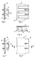
- the insulating parts 7 are expediently injection molded parts. They each consist of an end wall 8 and two L-shaped ribs 9 attached to the upper edge of the end wall 8.
- the ribs 9 protrude at least above the height of the coil into the space between the winding head 5 and the core package 4.
- the outer spacing of the ribs 9 is about equal to the core width.
- the ribs 9 have a transverse web 10 connecting their free ends, which serves in particular for the stability of the ribs 9.
- a clamp 11 is further placed for connecting the ends of the coil.
- the end wall 8 has on its upper side a recess 12 into which a corresponding projection 13 of the U-shaped housing part 6 engages. It can also be seen that the ends of the ribs 9 project beyond the coil into the end stop with the I-plates 1. This makes it easier to fix the core in relation to the I-plates during assembly. The ends of the ribs 9 are chamfered, which facilitates the insertion of the ribs between the core package 4 and the winding head 5. Finally, a U-shaped rib 14 is provided on the inside of the end wall 8, which is overlapped by the U-shaped housing part 6. The U-shaped housing 6 is expediently connected to the mounting plate 2 by spot welding.
- FIGS. 3 to 7 show two embodiments of the insulating material parts 7.
- a wavy stiffened end wall 8 is provided, while the insulating material part according to FIGS. 5 to 7 has a smooth plastic wall 8.
- Fig. 6 also shows that an additional transverse web 15 can be provided between the ribs 9 for reasons of stability. Otherwise, the insulating material part 7 shown in FIGS. 5 to 7 essentially corresponds to the insulating material part shown in FIGS. 1 and 2.
Landscapes
- Engineering & Computer Science (AREA)
- Power Engineering (AREA)
- Coils Or Transformers For Communication (AREA)
- Insulating Of Coils (AREA)
Applications Claiming Priority (2)
| Application Number | Priority Date | Filing Date | Title |
|---|---|---|---|
| DE3149853 | 1981-12-16 | ||
| DE19813149853 DE3149853C1 (de) | 1981-12-16 | 1981-12-16 | Drossel oder Transformator |
Publications (3)
| Publication Number | Publication Date |
|---|---|
| EP0081842A2 EP0081842A2 (de) | 1983-06-22 |
| EP0081842A3 EP0081842A3 (en) | 1983-07-20 |
| EP0081842B1 true EP0081842B1 (de) | 1986-03-26 |
Family
ID=6148907
Family Applications (1)
| Application Number | Title | Priority Date | Filing Date |
|---|---|---|---|
| EP19820111580 Expired EP0081842B1 (de) | 1981-12-16 | 1982-12-14 | Drossel oder Transformator |
Country Status (3)
| Country | Link |
|---|---|
| EP (1) | EP0081842B1 (enExample) |
| DE (1) | DE3149853C1 (enExample) |
| GR (1) | GR82296B (enExample) |
Families Citing this family (2)
| Publication number | Priority date | Publication date | Assignee | Title |
|---|---|---|---|---|
| FR2544543B1 (fr) * | 1983-04-15 | 1985-06-14 | Thomson Csf | Transformateur vhf de puissance |
| CH683214A5 (de) * | 1992-03-26 | 1994-01-31 | Knobel Lichttech | Gegen Berührung isolierter Kleinleistungstransformator. |
Family Cites Families (8)
| Publication number | Priority date | Publication date | Assignee | Title |
|---|---|---|---|---|
| CH391876A (de) * | 1961-11-09 | 1965-05-15 | Leuenberger H | Eisenkernanordnung in Drosselspule oder Transformator |
| FR1407092A (fr) * | 1964-04-06 | 1965-07-30 | Bobinage Pour L Ind Et La Radi | Procédé d'assemblage de circuits magnétiques pour transformateurs, sels ou autresappareils électriques statiques ou tournants |
| YU33139B (en) * | 1970-02-02 | 1976-04-30 | Elektrokovina Tovarna Elektrok | Dusilaka z brezvijacno sponko |
| NL157738B (nl) * | 1970-02-18 | 1978-08-15 | Philips Nv | Transformator. |
| DE7136866U (de) * | 1971-09-29 | 1972-06-22 | Plathner E Gmbh | Gehaeuse fuer transformatoren drosseln od.dgl. |
| DE2244158C3 (de) * | 1972-09-08 | 1979-09-06 | Fa. Hermann Schwabe, 7067 Urbach | Drossel oder Transformator, insbesondere als Vorschaltgerät für Gasentladungslampen |
| ATA909272A (de) * | 1972-10-24 | 1975-10-15 | Zumtobel Kg | Transformator oder drosselspule |
| DD148401A1 (de) * | 1980-01-07 | 1981-05-20 | Eberhard Wolf | Wickelkopfisolation |
-
1981
- 1981-12-16 DE DE19813149853 patent/DE3149853C1/de not_active Expired
-
1982
- 1982-07-23 GR GR68845A patent/GR82296B/el unknown
- 1982-12-14 EP EP19820111580 patent/EP0081842B1/de not_active Expired
Also Published As
| Publication number | Publication date |
|---|---|
| EP0081842A2 (de) | 1983-06-22 |
| EP0081842A3 (en) | 1983-07-20 |
| GR82296B (enExample) | 1984-12-13 |
| DE3149853C1 (de) | 1983-04-07 |
Similar Documents
| Publication | Publication Date | Title |
|---|---|---|
| DE2233571C3 (de) | Spulenkörper, insbesondere für Transformatoren | |
| DE2656050A1 (de) | Transformator | |
| DE8716135U1 (de) | Transformator, Drossel und dgl. | |
| EP0793243B1 (de) | Transformator | |
| EP0081842B1 (de) | Drossel oder Transformator | |
| DE2244158C3 (de) | Drossel oder Transformator, insbesondere als Vorschaltgerät für Gasentladungslampen | |
| EP0843325B1 (de) | Kleintransformator | |
| DE10131739A1 (de) | Stromwandler | |
| DE3506354C1 (de) | Elektromagnetisches Relais mit Isolierkappe und Verfahren zur Herstellung der Isolierkappe | |
| EP1636809B1 (de) | Induktives miniatur-bauelement für smd-montage | |
| DE9102841U1 (de) | Temperaturschalter mit Schalteinheit und Aufnahmeteil | |
| DE3020574A1 (de) | Wicklungstraeger fuer transformatoren und verfahren zur befestigung von drahtenden von transformatorwicklungen unter verwendung des wicklungstraegers | |
| EP0121676B1 (de) | Drossel oder Transformator, insbesondere als Vorschaltgerät für Gasentladungslampen | |
| DE8115956U1 (de) | Induktives geraet | |
| EP0222687B1 (de) | Stromwandler für einen Leistungsschalter | |
| EP0240737B1 (de) | Vorschaltdrossel, insbesondere für Gasentladungslampen | |
| DE2950727C2 (de) | Drosselspule für das Vorschaltgerät von Leuchtstofflampen | |
| DE4036275A1 (de) | Ringfoermiger spulenkoerper fuer klein- und sicherheitstranformatoren und verfahren zu seiner herstellung | |
| EP0152096B1 (de) | Vorschaltgerät für Gasentladungslampen | |
| DE3312513A1 (de) | Transformator | |
| DE3108555C2 (de) | Verbindungsanordnung zum dichten Verbinden von zwei Gehäuseteilen aus Kunststoff für elektrische, spannungsführende Bauteile | |
| DD281047A1 (de) | Isolationsanordnung mit distanzelementen fuer wicklungsausleitungen von transformatoren und drosselspulen | |
| DE2725450C2 (de) | Entmagnetisierungseinrichtung für Farbfernseher | |
| DE10114744A1 (de) | Einrichtung zum Bilden von Kühlluft-Kanälen | |
| DE2837351C2 (de) | Spulenkörper für die Statorwicklung einer kleinen elektrischen Maschine |
Legal Events
| Date | Code | Title | Description |
|---|---|---|---|
| PUAI | Public reference made under article 153(3) epc to a published international application that has entered the european phase |
Free format text: ORIGINAL CODE: 0009012 |
|
| PUAL | Search report despatched |
Free format text: ORIGINAL CODE: 0009013 |
|
| AK | Designated contracting states |
Designated state(s): FR GB IT NL SE |
|
| AK | Designated contracting states |
Designated state(s): FR GB IT NL SE |
|
| 17P | Request for examination filed |
Effective date: 19830908 |
|
| ITF | It: translation for a ep patent filed | ||
| GRAA | (expected) grant |
Free format text: ORIGINAL CODE: 0009210 |
|
| AK | Designated contracting states |
Kind code of ref document: B1 Designated state(s): FR GB IT NL SE |
|
| ET | Fr: translation filed | ||
| PLBE | No opposition filed within time limit |
Free format text: ORIGINAL CODE: 0009261 |
|
| STAA | Information on the status of an ep patent application or granted ep patent |
Free format text: STATUS: NO OPPOSITION FILED WITHIN TIME LIMIT |
|
| 26N | No opposition filed | ||
| PGFP | Annual fee paid to national office [announced via postgrant information from national office to epo] |
Ref country code: GB Payment date: 19901214 Year of fee payment: 9 |
|
| PGFP | Annual fee paid to national office [announced via postgrant information from national office to epo] |
Ref country code: SE Payment date: 19901221 Year of fee payment: 9 |
|
| PGFP | Annual fee paid to national office [announced via postgrant information from national office to epo] |
Ref country code: FR Payment date: 19901228 Year of fee payment: 9 |
|
| ITTA | It: last paid annual fee | ||
| PGFP | Annual fee paid to national office [announced via postgrant information from national office to epo] |
Ref country code: NL Payment date: 19901231 Year of fee payment: 9 |
|
| PG25 | Lapsed in a contracting state [announced via postgrant information from national office to epo] |
Ref country code: GB Effective date: 19911214 |
|
| PG25 | Lapsed in a contracting state [announced via postgrant information from national office to epo] |
Ref country code: SE Effective date: 19911215 |
|
| PG25 | Lapsed in a contracting state [announced via postgrant information from national office to epo] |
Ref country code: NL Effective date: 19920701 |
|
| GBPC | Gb: european patent ceased through non-payment of renewal fee | ||
| NLV4 | Nl: lapsed or anulled due to non-payment of the annual fee | ||
| PG25 | Lapsed in a contracting state [announced via postgrant information from national office to epo] |
Ref country code: FR Effective date: 19920831 |
|
| REG | Reference to a national code |
Ref country code: FR Ref legal event code: ST |
|
| EUG | Se: european patent has lapsed |
Ref document number: 82111580.5 Effective date: 19920704 |