EP0081608B1 - Space frame - Google Patents
Space frame Download PDFInfo
- Publication number
- EP0081608B1 EP0081608B1 EP81110501A EP81110501A EP0081608B1 EP 0081608 B1 EP0081608 B1 EP 0081608B1 EP 81110501 A EP81110501 A EP 81110501A EP 81110501 A EP81110501 A EP 81110501A EP 0081608 B1 EP0081608 B1 EP 0081608B1
- Authority
- EP
- European Patent Office
- Prior art keywords
- node
- screw
- interior
- screw connectors
- tubular struts
- Prior art date
- Legal status (The legal status is an assumption and is not a legal conclusion. Google has not performed a legal analysis and makes no representation as to the accuracy of the status listed.)
- Expired
Links
Images

Classifications
-
- E—FIXED CONSTRUCTIONS
- E04—BUILDING
- E04B—GENERAL BUILDING CONSTRUCTIONS; WALLS, e.g. PARTITIONS; ROOFS; FLOORS; CEILINGS; INSULATION OR OTHER PROTECTION OF BUILDINGS
- E04B1/00—Constructions in general; Structures which are not restricted either to walls, e.g. partitions, or floors or ceilings or roofs
- E04B1/18—Structures comprising elongated load-supporting parts, e.g. columns, girders, skeletons
- E04B1/19—Three-dimensional framework structures
- E04B1/1903—Connecting nodes specially adapted therefor
- E04B1/1906—Connecting nodes specially adapted therefor with central spherical, semispherical or polyhedral connecting element
-
- E—FIXED CONSTRUCTIONS
- E04—BUILDING
- E04B—GENERAL BUILDING CONSTRUCTIONS; WALLS, e.g. PARTITIONS; ROOFS; FLOORS; CEILINGS; INSULATION OR OTHER PROTECTION OF BUILDINGS
- E04B1/00—Constructions in general; Structures which are not restricted either to walls, e.g. partitions, or floors or ceilings or roofs
- E04B1/18—Structures comprising elongated load-supporting parts, e.g. columns, girders, skeletons
- E04B1/19—Three-dimensional framework structures
- E04B2001/1924—Struts specially adapted therefor
- E04B2001/1927—Struts specially adapted therefor of essentially circular cross section
-
- E—FIXED CONSTRUCTIONS
- E04—BUILDING
- E04B—GENERAL BUILDING CONSTRUCTIONS; WALLS, e.g. PARTITIONS; ROOFS; FLOORS; CEILINGS; INSULATION OR OTHER PROTECTION OF BUILDINGS
- E04B1/00—Constructions in general; Structures which are not restricted either to walls, e.g. partitions, or floors or ceilings or roofs
- E04B1/18—Structures comprising elongated load-supporting parts, e.g. columns, girders, skeletons
- E04B1/19—Three-dimensional framework structures
- E04B2001/1957—Details of connections between nodes and struts
- E04B2001/196—Screw connections with axis parallel to the main axis of the strut
Definitions
- the invention relates to a space frame consisting of tubular rods, the ends of the tubular rods connecting hollow spherical knot pieces with holes in the knot pieces for screw connections between the pipe rod ends and the knot pieces, the screw connections protrude into the interior of the knot piece, and the knot pieces have closable mounting openings through which the screw connections in the interior are accessible for the purpose of assembly.
- These space frameworks are scaffolds that are built on playgrounds for children, for example, and serve as climbing frames.
- the scaffolding can also carry nets that serve the same purpose.
- Spatial frameworks of similar training can be used as exhibition stands, as hall roofs, as partition walls, possibly also as scaffolding or for similar purposes.
- DE-AS 27 36 635 describes such a screw connection, wherein a screw is used between the tube rod end and the node piece, which rests with its head lying in the tube on a connecting element at the tube end and by means of a ring-shaped or disk-shaped part on the outside Has key surfaces, can be rotated. In this way, the connecting screw can be screwed into a threaded hole in the node piece.
- the type of fastening of the tube rod ends to the node piece is visible from the outside, which is often undesirable.
- the fastening means for example the elements with the wrench flats, are also accessible from the outside, and precisely because of the wrench flats, sharp edges at the connection points of the pipe rod ends on the node piece are unavoidable.
- FR-A-2 452 628 also describes a node piece which can be connected to pipe ends by means of screws. It is proposed that the pipe ends taper towards the node piece, since otherwise the assembly is impossible. The supporting end of the pipe end is supported on the small remaining end surface at the end of the pipe, which is adapted to the curvature of the node part. This contact area is very small. If transverse forces occur in the area of the connection between the pipe end and the node piece, these must only be absorbed by the fastening screw. Due to the small support surface, moments are difficult to transmit. In addition, the pipes, which have a narrow cross section at their end, require an increased design effort.
- FR-A-2 439 935 describes a similar construction with conical pipe ends.
- the pipe ends do not extend to the node piece, but the connection between the node piece and the pipe consists of the fastening screw, which entails a high risk of injury.
- a cover is arranged, but this means an additional effort.
- the invention proposes that the node piece has annular recesses on the outside, into which the ends of the tubular rods, which have an undiminished cross-section, extend as far as the node piece.
- the invention not only a simple smooth exterior is obtained for the knot pieces and the pipe pieces.
- the invention also provides good support for the pipe rod ends on the node piece, so that not only tensile and compressive forces, but also bending moments can be transmitted well.
- Another advantage is that commercially available pipes can be used in this invention, which reduces the design effort.
- the node piece 3 of the embodiment of the invention essentially has the shape of a hollow ball.
- the invention can be used not only with geometrically precise hollow spheres, but also with the use of node pieces that deviate from the spherical shape and are designed, for example, as a rotational ellipsoid.
- the outer surface of the node piece can also be composed of a large number of flat or slightly curved partial surfaces, if this appears to be advantageous for other purposes from the special application purposes of the invention.
- a spherical shape is preferred, since in a space framework not all node pieces have the same design or the node pieces are to be provided with different bores 4 or 5 for connecting the ends 2 of the tubular rods 1.
- the interior 7 of the node piece 3 is accessible through the mounting opening 8, which is closed by a lens-shaped sealing plug 10.
- this sealing plug has a snap closure by appropriately designing its inner flange 14.
- the screw connections 6 for fastening the pipes to the node pieces of a space framework will have a similar design.
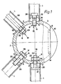
- Fig. 1 of the drawings four different variants of such screw connections are indicated.
- a screw 20 with a head 21, which is adapted to the inside diameter of the tubular rod 1 is welded into the end 2 of the tubular rod.
- the shaft 22 of this screw 20 is held by the nut 23.
- a washer is indicated at 24.
- a screw 27 engages in the disk 25, which is welded into the end of the tubular rod 1.
- the head 26 is accessible from the interior 7.
- a tie rod 28 is provided which extends between two knot pieces and carries a thread 29 for the nut 30 at the end.
- the tie rod 28 is separate from the tube 1 and presses it into the recess 15.
- a screw 31 is inserted into the disk 25 and secured against falling out by the ring 32.
- the screw 31 can be rotated relative to the shank 25 and can be screwed in from the interior 7, for example by means of a special tool, for which the screw 31 has a suitable inner recess, for example.
- assembly can also be carried out from the other end of the tubular rod 2 before this end is connected to a node piece which then has, for example, a screw connection according to variant 16 or 17.
- annular recesses 13 are machined into the node piece 3, for example cast or screwed in, which receive the ends of the tubes 1, which are not shown.
- the illustration in FIG. 2 makes it clear that the invention can be used without further ado if the tubular rods form an angle of 90 ° or 45 ° with one another, but that any other orientation of the tubular rods can also be controlled.
- the mounting opening 8 is to be arranged taking into account the arrangement of the holes 4 and 5, respectively.
- the node piece 3 consists of the two parts 11 and 12, each of which has approximately hemispherical shape. It is possible with the invention to subdivide the node piece exactly in a central plane. However, the two parts 11 and 12 can also have different dimensions.
- the connection of the two hemispheres 11 and 12 takes place by means of a screw 33, the recessed head 34 of which is covered by a cover 35 made of elastic material. At the parting plane of the two hemispheres 11 and 12 there is the mounting opening 9.
- the holes 4 and 5 for the screw connections can be provided not only in one hemispherical part 11, but also in the other part 12.
- the node pieces 3 are cast, for example, from aluminum or an aluminum alloy. With a diameter of the tubular bars of approximately 60 millimeters, it is advisable to provide an outer diameter of approximately 250 millimeters for the node piece.
Abstract
Description
Die Erfindung betrifft ein Raumfachwerk, bestehend aus RohrstÄben, die Enden der RohrstÄbe verbindenden hohlkugelfÖrmigen Knotenstücken mit Bohrungen in den Knotenstücken für Schraubverbindungen zwischen den Rohrstabenden und den Knotenstücken, wobei die Schraubverbindungen in den Innenraum des Knotenstückes hineinragen, und die Knotenstücke verschließbare Montageöffnungen besitzen, durch die die Schraubverbindungen im Innenraum zum Zwecke der Montage zugÄnglich sind.The invention relates to a space frame consisting of tubular rods, the ends of the tubular rods connecting hollow spherical knot pieces with holes in the knot pieces for screw connections between the pipe rod ends and the knot pieces, the screw connections protrude into the interior of the knot piece, and the knot pieces have closable mounting openings through which the screw connections in the interior are accessible for the purpose of assembly.
Raumfachwerke der vorstehend beschriebenen Art sind in verschiedenen Ausführungsformen bekannt geworden.Space trusses of the type described above have become known in various embodiments.
Diese Raumfachwerke sind Gerüste, die beispielsweise auf SpielplÄtzen für Kinder aufgebaut werden und als Klettergerüste dienen. Die Gerüste kÖnnen auch dem gleichen Zweck dienende Netze tragen.These space frameworks are scaffolds that are built on playgrounds for children, for example, and serve as climbing frames. The scaffolding can also carry nets that serve the same purpose.
Raumfachwerke ähnlicher Ausbildung kÖnnen als MessestÄnde, als HallendÄcher, als TrennwÄnde, gegebenenfalls auch als Baugerüste oder für ähnliche Zwecke Verwendung finden.Spatial frameworks of similar training can be used as exhibition stands, as hall roofs, as partition walls, possibly also as scaffolding or for similar purposes.
Ein wesentliches technisches Problem derartiger Raumfachwerke ist in der Anordnung und Ausbildung der Verbindung der Rohrstabenden und der Knotenstücke zu sehen. Die DE-AS 27 36 635 beschreibt eine derartige Schraubverbindung, wobei zwischen dem Rohrstabende und dem Knotenstück eine Schraube benützt wird, die mit ihrem im Rohr liegenden Kopf an einem Anschlußelement am Rohrende anliegt und mittels eines ring- oder scheibenfÖrmigen Teiles, das auf der Außenseite SchlüsselflÄchen aufweist, gedreht werden kann. Auf diese Weise lÄßt sich die Verbindungsschraube in eine Gewindebohrung des Knotenstückes eindrehen.An essential technical problem of such space trusses can be seen in the arrangement and design of the connection of the tube rod ends and the node pieces. DE-AS 27 36 635 describes such a screw connection, wherein a screw is used between the tube rod end and the node piece, which rests with its head lying in the tube on a connecting element at the tube end and by means of a ring-shaped or disk-shaped part on the outside Has key surfaces, can be rotated. In this way, the connecting screw can be screwed into a threaded hole in the node piece.
Bei Schraubverbindungen bzw. Raumfachwerken der beschriebenen Art ist die Art der Befestigung der Rohrstabenden am Knotenstück von außen sichtbar, was hÄufig unerwünscht ist. Insbesondere sind auch die Befestigungsmittel, beispielsweise die Elemente mit den SchlüsselflÄchen, von außen zugÄnglich, und gerade wegen der SchlüsselflÄchen sind scharfe Kanten an den Anschlußstellen der Rohrstabenden am Knotenstück unvermeidbar.In the case of screw connections or space trusses of the type described, the type of fastening of the tube rod ends to the node piece is visible from the outside, which is often undesirable. In particular, the fastening means, for example the elements with the wrench flats, are also accessible from the outside, and precisely because of the wrench flats, sharp edges at the connection points of the pipe rod ends on the node piece are unavoidable.
Die Verwendung derartiger Raumfachwerke als Klettergerüste für SpielplÄtze bringt somit eine erhebliche Unfallgefahr mit sich. Zu beachten ist, daß insbesondere an den Anschlußstellen mit einem Kontakt mit den Gerüstteilen gerechnet werden muß, beispielsweise bei einem beabsichtigten oder unbeabsichtigten Abrutschen an den RohrstÄben.The use of such trusses as climbing frames for playgrounds therefore entails a considerable risk of accidents. It should be noted that, especially at the connection points, contact with the scaffolding parts must be expected, for example if the pipe rods slide intentionally or unintentionally.
Die besondere Bauweise der bekannten Schraubverbindungen, wobei bei der Montage die Schraube das Rohrstabende über das Element mit den SchlüsselflÄchen auf das Knotenstück preßt, führt dazu, daß beim Anschrauben das Rohr beim Schraubvorgang mit verdreht wird. Gekrümmte oder geknickte RohrstÄbe, die manchmal zu verwenden sind, sind daher nur schwer auszurichten. Auch benÖtigen die mit den SchlüsselflÄchen versehenen Schraubelemente für die Montage einen ausreichenden Abstand von Nachbarelementen, was oft schwierig zu vefWirklichen ist. QuerkrÄfte müssen allein von der Befestigungsschraube aufgenommen werden.The special design of the known screw connections, the screw pressing the pipe rod end over the element with the key surfaces onto the node piece during assembly, means that when screwing on the pipe is also rotated during the screwing process. Curved or kinked pipe rods, which are sometimes to be used, are therefore difficult to align. The provided with the key areas screw elements for the assembly require a sufficient distance from neighboring elements, which is often difficult to irklichen vef W. Lateral forces have to be absorbed by the fastening screw alone.
In der FR-A-2 452 628 wird ebenfalls ein Knotenstück beschrieben, das mittels Schrauben mit Rohrenden verbunden werden kann. Dabei wird vorgeschlagen, daß die Rohrenden zum Knotenstück hin konisch zulaufen, da sonst die Montage unmÖglich ist. Die Abstützung der des Kohrenden an den Knotenstücken erfolgt auf der kleinen verbliebenen EndflÄche am Rohrende, die der WÖlbung des Knotenstückes angepaßt ist. Diese AuflageflÄche ist aber sehr klein. Falls QuerkrÄfte im Bereich der Verbindung zwischen Rohrende und Knotenstück auftreten, müssen diese allein von der Befestigungsschraube aufgenommen werden. Wegen der kleinen AbstützflÄche kÖnnen Momente nur schlecht übertragen werden. Dazu kommt, daß die Rohre, die einen verengten Querschnitt an ihrem Ende besitzen, einen erhÖhten konstruktiven Aufwand erfordern.FR-A-2 452 628 also describes a node piece which can be connected to pipe ends by means of screws. It is proposed that the pipe ends taper towards the node piece, since otherwise the assembly is impossible. The supporting end of the pipe end is supported on the small remaining end surface at the end of the pipe, which is adapted to the curvature of the node part. This contact area is very small. If transverse forces occur in the area of the connection between the pipe end and the node piece, these must only be absorbed by the fastening screw. Due to the small support surface, moments are difficult to transmit. In addition, the pipes, which have a narrow cross section at their end, require an increased design effort.
Eine ähnliche Bauweise mit konischen Rohrenden beschreibt die FR-A-2 439 935. Die Rohrenden reichen jedoch nicht bis zum Knotenstück, sondern die Verbindung zwischen Knotenstück und Rohr besteht aus der Befestigungsschraube, was eine hohe Verletzungsgefahr mit sich bringt. Um diese Gefahr zu vermindern, wird eine Abdeckung angeordnet, was aber einen zusÄtzlichen Aufwand bedeutet.FR-A-2 439 935 describes a similar construction with conical pipe ends. However, the pipe ends do not extend to the node piece, but the connection between the node piece and the pipe consists of the fastening screw, which entails a high risk of injury. In order to reduce this risk, a cover is arranged, but this means an additional effort.
Es ist ein Ziel der Erfindung, ein Raumfachwerk der eingangs beschriebenen Art dahingehend zu verbessern, daß weitgehend glatte AußenflÄchen erhalten werden, durch die die Unfallgefahr verringert wird, und daß hohe QuerkrÄfte und Momente gut übertragen werden.It is an object of the invention to improve a space framework of the type described at the outset in such a way that largely smooth outer surfaces are obtained, by means of which the risk of accidents is reduced, and that high transverse forces and moments are transmitted well.
Zur LÖsung dieser Aufgabe schlÄgt die Erfindung vor, daß das Knotenstück auf der Außenseite ringfÖrmige Ausnehmungen aufweist, in die unmittelbar die Enden der mit unvermindertem Querschnitt bis zum Knotenstück hingeführten RohrstÄbe eingreifen.In order to achieve this object, the invention proposes that the node piece has annular recesses on the outside, into which the ends of the tubular rods, which have an undiminished cross-section, extend as far as the node piece.
Bei der Erfindung wird nicht nur ein einfaches glattes Äußere für die Knotenstücke und die Rohrstücke erhalten. Insbesondere erreicht die Erfindung auch eine gute Abstützung der Rohrstabenden am Knotenstück, so daß nicht nur Zug- und DruckkrÄfte, sondern auch Biegemomente gut übertragen werden kÖnnen.In the invention, not only a simple smooth exterior is obtained for the knot pieces and the pipe pieces. In particular, the invention also provides good support for the pipe rod ends on the node piece, so that not only tensile and compressive forces, but also bending moments can be transmitted well.
Ein weiterer Vorteil ist, daß bei dieser Erfindung handelsübliche Rohre verwendet werden kÖnnen, was den konstruktiven Aufwand verringert.Another advantage is that commercially available pipes can be used in this invention, which reduces the design effort.
In der Zeichnung sind einige Ausführungsbeispiele der Erfindung schematisch dargestellt. Es zeigen:
- Fig. 1 einen teilweisen Schnitt durch ein Knotenstück mit angeschlossenen Rohrstabenden eines Raumfachwerks gemÄß der Erfindung,
- Fig. 2 einen Schnitt durch ein Knotenstück eines abgewandelten Ausführungsbeispiels und
- Fig. 3 einen Schnitt durch ein weiteres Knotenstück einer anderen Ausbildungsform der Erfindung.
- 1 shows a partial section through a node piece with connected tube rod ends of a space framework according to the invention,
- Fig. 2 shows a section through a node piece of a modified embodiment and
- Fig. 3 shows a section through another node piece of another embodiment of the invention.
Das Knotenstück 3 des Ausführungsbeispiels der Erfindung besitzt im wesentlichen die Form einer Hohlkugel. Die Erfindung ist aber nicht nur bei geometrisch exakten Hohlkugeln anwendbar, sondern auch unter Verwendung solcher Knotenstücke, die von der Kugelform abweichen und beispielsweise als Rotations-Ellipsoid ausgebildet sind. Die AußenflÄche des Knotenstückes kann sich auch aus einer Vielzahl ebener oder leicht gekrümmter TeilflÄchen zusammensetzen, wenn dies für die besonderen Anwendungszwecke der Erfindung aus anderen Überlegungen günstig erscheint.The
Entsprechendes gilt für die Kontur des Innenraums 7.The same applies to the contour of the
Im allgemeinen ist jedoch eine Kugelform zu bevorzugen, da bei einem Raumfachwerk nicht alle Knotenstücke eine gleichartige Ausbildung besitzen bzw. die Knotenstücke mit verschiedenen Bohrungen 4 oder 5 für den Anschluß der Enden 2 der RohrstÄbe 1 zu versehen sind. Im Ausführungsbeispiel der Fig. 1 ist der Innenraum 7 des Knotenstückes 3 durch die MontageÖffnung 8 zugÄnglich, die von einem linsenfÖrmigen Verschlußstopfen 10 verschlossen ist. Dieser Verschlußstopfen besitzt, wie an sich bekannt, einen Schnappverschluß durch entsprechende Ausbildung seines Innenflansches 14.In general, however, a spherical shape is preferred, since in a space framework not all node pieces have the same design or the node pieces are to be provided with
Für den Anschluß der Enden 2 der RohrstÄbe 1 sind im Knotenstück 3 einfache Bohrungen 4 vorgesehen bzw. auch Gewindebohrungen 5. Auf der Außenseite sind die Bohrungen 4 bzw. 5 von den Ausnehmungen 15 umgeben, in die die Enden 2 der RohrstÄbe 1 eingreifen.For the connection of the
Im allgemeinen werden die Schraubverbindungen 6 zur Befestigung der Rohre an den Knotenstücken eines Raumfachwerkes eine gleichartige Ausbildung aufweisen. In der Fig. 1 der Zeichnungen sind vier verschieden Varianten solcher Schraubverbindungen angedeutet. Bei der Variante 16 ist eine Schraube 20 mit einem Kopf 21, der dem Innendurchmesser des Rohrstabes 1 angepaßt ist, in das Ende 2 des Rohrstabes eingeschweißt. Der Schaft 22 dieser Schraube 20 wird durch die Mutter 23 gehalten. Eine Unterlegscheibe ist mit 24 bezeichnet.In general, the
Bei der Variante 17 greift eine Schraube 27 in die Scheibe 25 ein, die in das Ende des Rohrstabs 1 eingeschweißt ist.In the
Der Kopf 26 ist vom Innenraum 7 her zugÄnglich.The
Bei der Variante 18 ist ein Zuganker 28 vorgesehen, der sich zwischen zwei Knotenstücken erstreckt und jeweils am Ende ein Gewinde 29 für die Mutter 30 trÄgt. Der Zuganker 28 ist getrennt vom Rohr 1 und drückt dieses in die Ausnehmung 15.In the
Bei der Variante 19 ist in die Scheibe 25 eine Schraube 31 eingesetzt und durch den Ring 32 gegen Herausfallen gesichert. Die Schraube 31 ist gegenüber der Schebe 25 verdrehbar und kann beispielsweise mittels eines Spezialwerkzeuges vom Innenraum 7 her eingedreht werden, wofür zum Beispiel die Schraube 31 eine geeignete Innenausnehmung aufweist.In the
Bei entsprechender Ausbildung des Kopfes 36 kann auch eine Montage vom anderen Ende des Rohrstabes 2 her erfolgen, bevor dieses Ende mit einem Knotenstück verbunden ist, daß dann beispielsweise eine Schraubverbindung gemÄß der Variante 16 oder 17 besitzt.With a corresponding design of the
Beim Ausführungsbeispiel nach der Fig. 2 sind in das Knotenstück 3 ringfÖrmige Ausnehmungen 13 eingearbeitet, beispielsweise eingegossen oder eingedreht, die die nicht dargestellten Enden der Rohre 1 aufnehmen. Die Darstellung der Fig. 2 macht deutlich, daß die Erfindung ohne weiteres anwendbar ist, wenn die RohrstÄbe miteinander einen Winkel von 90° oder 45° einschließen, daß aber auch jede andere Ausrichtung der RohrstÄbe beherrschbar ist. Je nach der GrÖße des Knotenstückes bzw. der Durchmesser der Hohlkugel und der RohrstÄbe kann natürlich ein bestimmter spitzer Winkel nicht unterschritten werden.In the exemplary embodiment according to FIG. 2,
Die MontageÖffnung 8 ist jeweils unter Berücksichtigung der Anordnung der Bohrungen 4 bzw. 5 anzuordnen.The mounting opening 8 is to be arranged taking into account the arrangement of the
Bei der Variante nach der Fig. 3 besteht das Knotenstück 3 aus den beiden Teilen 11 und 12, die jeweils annÄhernd Halbkugelform aufweisen. Es ist bei der Erfindung mÖglich, das Knotenstück genau in einer Mittelebene zu unterteilen. Die beiden Teile 11 und 12 kÖnnen jedoch auch unterschiedliche Dimensionen besitzen. Die Verbindung der beiden Halbkugeln 11 und 12 erfolgt mittels einer Schraube 33, deren versenkt angeordneter Kopf 34 durch eine Abdeckung 35 aus elastischem Material verdeckt ist. An der Trennebene der beiden Halbkugeln 11 und 12 ergibt sich die MontageÖffnung 9.In the variant according to FIG. 3, the
Falls es sich als notwendig erweist, kÖnnen die Bohrungen 4 bzw. 5 für die Schraubverbindungen nicht nur in dem einen halbkugelfÖrmigen Teil 11, sondern auch im anderen Teil 12 vorgesehen werden.If it proves necessary, the
Die Knotenstücke 3 werden bei der Erfindung beispielsweise aus Aluminium oder einer Aluminiumlegierung gegossen. Bei einem Durchmesser der RohrstÄbe von etwa 60 Millimetern empfiehlt es sich, beim Knotenstück einen Außendurchmesser von etwa 250 Millimeter vorzusehen.In the invention, the
Claims (1)
- Space frame formed from tubular struts (1) which have ends (2) for connection with hollow spherical node members (3), said node members (3) having bores (4,5) therein to receive screw connectors (6) between the ends of the tubular struts and the node member so that the screw connectors project into the interior (7) of the node member, the node members having closeable assembly apertures (8, 9) through which the screw connectors in the interior are accessible for assembly purposes, characterised in that the node member is provided on its external surface with annular cut-out portions (13) in which are directly engaged the ends (2) of the tubular struts (I), which lead up to the node member (3) with no reduction in their cross section.
Priority Applications (3)
| Application Number | Priority Date | Filing Date | Title |
|---|---|---|---|
| DE8181110501T DE3173539D1 (en) | 1981-12-16 | 1981-12-16 | Space frame |
| AT81110501T ATE17509T1 (en) | 1981-12-16 | 1981-12-16 | SPACE FRAMEWORK. |
| EP81110501A EP0081608B1 (en) | 1981-12-16 | 1981-12-16 | Space frame |
Applications Claiming Priority (1)
| Application Number | Priority Date | Filing Date | Title |
|---|---|---|---|
| EP81110501A EP0081608B1 (en) | 1981-12-16 | 1981-12-16 | Space frame |
Publications (2)
| Publication Number | Publication Date |
|---|---|
| EP0081608A1 EP0081608A1 (en) | 1983-06-22 |
| EP0081608B1 true EP0081608B1 (en) | 1986-01-15 |
Family
ID=8188072
Family Applications (1)
| Application Number | Title | Priority Date | Filing Date |
|---|---|---|---|
| EP81110501A Expired EP0081608B1 (en) | 1981-12-16 | 1981-12-16 | Space frame |
Country Status (3)
| Country | Link |
|---|---|
| EP (1) | EP0081608B1 (en) |
| AT (1) | ATE17509T1 (en) |
| DE (1) | DE3173539D1 (en) |
Cited By (1)
| Publication number | Priority date | Publication date | Assignee | Title |
|---|---|---|---|---|
| DE3406550A1 (en) * | 1984-02-23 | 1985-09-05 | Ed. Züblin AG, 7000 Stuttgart | Joint connection of a framework bar comprising a rectangular pipe |
Families Citing this family (10)
| Publication number | Priority date | Publication date | Assignee | Title |
|---|---|---|---|---|
| DE3471125D1 (en) * | 1984-02-13 | 1988-06-16 | Inchaurbe Jose Maria Jav Galan | Spacial structure |
| DE3405282A1 (en) * | 1984-02-15 | 1985-08-22 | Leitner GmbH, 7000 Stuttgart | NODE POINT FOR CONNECTING ADDITIONAL COMPONENTS |
| DE3504807A1 (en) * | 1985-02-13 | 1986-08-14 | SCHÜCO Heinz Schürmann GmbH & Co, 4800 Bielefeld | SPACIOUS |
| FR2590332B1 (en) * | 1985-11-19 | 1988-05-27 | Chamayou Gerard | ASSEMBLY DEVICE FOR TUBES OR BARS |
| EP0228930A1 (en) * | 1985-11-19 | 1987-07-15 | Gérard Chamayou | Device for assembling tubes or rods |
| FR2592446B1 (en) * | 1985-12-27 | 1988-05-27 | Chamayou Gerard | ASSEMBLY DEVICE FOR TUBES OR BARS WITH TAPPED MOUTHPIECES |
| ES2092938B1 (en) * | 1993-06-10 | 1997-11-16 | Univ De A Coru A | FLAT OR SPACE STRUCTURE OF HOLLOW SECTION BARS OF GLUE LAMINATED WOOD. |
| DE102007036764B3 (en) * | 2007-08-03 | 2009-01-29 | Butzkies Stahlbau Gmbh | Tower for e.g. wind energy plant, has lattice shaped tower section with three corner posts, and tubular tower section with circular cross section, where free ends of inner profiles are connected with inner wall of tubular tower section |
| CN101793058A (en) * | 2010-03-09 | 2010-08-04 | 浙江东南网架股份有限公司 | Bowl type bolt hollow sphere node |
| CH717621A1 (en) * | 2020-07-07 | 2022-01-14 | Cataldo Antonio | Modular structure. |
Family Cites Families (3)
| Publication number | Priority date | Publication date | Assignee | Title |
|---|---|---|---|---|
| DE2736635C2 (en) * | 1977-08-13 | 1982-02-11 | Mero-Raumstruktur GmbH & Co Würzburg, 8700 Würzburg | Screw connection between the tubular rods and a junction piece of junction connections of a space framework |
| FR2439935A1 (en) * | 1978-10-25 | 1980-05-23 | Bretagne Ste Metallurg | Prefabricated roof framework - has tubular supports bolted onto hollow spheres at various angles |
| FR2452628A1 (en) * | 1979-03-27 | 1980-10-24 | Chateau Stephane Du | ASSEMBLY OF BARS FOR CROSSLINKED STRUCTURES OF METAL FRAMES |
-
1981
- 1981-12-16 EP EP81110501A patent/EP0081608B1/en not_active Expired
- 1981-12-16 AT AT81110501T patent/ATE17509T1/en not_active IP Right Cessation
- 1981-12-16 DE DE8181110501T patent/DE3173539D1/en not_active Expired
Cited By (1)
| Publication number | Priority date | Publication date | Assignee | Title |
|---|---|---|---|---|
| DE3406550A1 (en) * | 1984-02-23 | 1985-09-05 | Ed. Züblin AG, 7000 Stuttgart | Joint connection of a framework bar comprising a rectangular pipe |
Also Published As
| Publication number | Publication date |
|---|---|
| DE3173539D1 (en) | 1986-02-27 |
| ATE17509T1 (en) | 1986-02-15 |
| EP0081608A1 (en) | 1983-06-22 |
Similar Documents
| Publication | Publication Date | Title |
|---|---|---|
| EP0191426B1 (en) | Three-dimensional framework structure | |
| DE2520510A1 (en) | CONNECTING NODE | |
| EP0081608B1 (en) | Space frame | |
| DE1609341B2 (en) | BUILDING CONSTRUCTION IN THE FORM OF A ROTATING AREA | |
| DE901955C (en) | Component for trusses, in particular scaffolding made of steel pipes, with coupling device | |
| DE2246478C3 (en) | Junction connection of spatial framework constructions | |
| DE2526660C3 (en) | Building construction with a space framework made of bars and junction pieces and an outer skin | |
| DE3636462C2 (en) | ||
| DE2743269C2 (en) | Junction point connection for space frameworks made of rods and ball-like junction pieces | |
| DE3111930A1 (en) | ROD JOINT CLAMP | |
| DE3629135C2 (en) | ||
| DE2451133C2 (en) | table | |
| DE1929847A1 (en) | Method of forming anchoring heads on metal rods | |
| EP0229605B1 (en) | Joint connection for space frames | |
| EP0153633B1 (en) | Connection node for joining adjacent building parts | |
| DE2227755C2 (en) | Electrical isolator | |
| DE1409068B1 (en) | Node for spatial structures | |
| AT218715B (en) | Component for bridges, collapsible halls, armor or the like. | |
| DE3122873A1 (en) | Device which comprises an abutment piece and a nut element, in particular for the building industry | |
| DE1409068C (en) | Junction piece for spatial structures | |
| CH682099A5 (en) | Knot piece for fixture of framework bars - comprises core piece with cylindrical throat around which collar comprising two half rings is rotatably located | |
| DE2022614C3 (en) | Column-shaped component | |
| AT213989B (en) | Fitting for insulator links of a multi-link insulator chain for high-voltage lines connected to one another by connecting eyes | |
| DE1975449U (en) | LENGTH-CHANGEABLE BODY. | |
| AT222199B (en) | Long rod insulator combination for supports |
Legal Events
| Date | Code | Title | Description |
|---|---|---|---|
| PUAI | Public reference made under article 153(3) epc to a published international application that has entered the european phase |
Free format text: ORIGINAL CODE: 0009012 |
|
| AK | Designated contracting states |
Designated state(s): AT BE CH DE FR GB IT LI LU NL SE |
|
| 17P | Request for examination filed |
Effective date: 19830709 |
|
| RAP1 | Party data changed (applicant data changed or rights of an application transferred) |
Owner name: PFEIFER SEIL- UND HEBETECHNIK GMBH & CO. |
|
| ITF | It: translation for a ep patent filed |
Owner name: ING. MISITANO A. GIULIO |
|
| GRAA | (expected) grant |
Free format text: ORIGINAL CODE: 0009210 |
|
| AK | Designated contracting states |
Designated state(s): AT BE CH DE FR GB IT LI LU NL SE |
|
| REF | Corresponds to: |
Ref document number: 17509 Country of ref document: AT Date of ref document: 19860215 Kind code of ref document: T |
|
| ET | Fr: translation filed | ||
| REF | Corresponds to: |
Ref document number: 3173539 Country of ref document: DE Date of ref document: 19860227 |
|
| R20 | Corrections of a patent specification |
Effective date: 19860407 |
|
| PLBE | No opposition filed within time limit |
Free format text: ORIGINAL CODE: 0009261 |
|
| STAA | Information on the status of an ep patent application or granted ep patent |
Free format text: STATUS: NO OPPOSITION FILED WITHIN TIME LIMIT |
|
| 26N | No opposition filed | ||
| PG25 | Lapsed in a contracting state [announced via postgrant information from national office to epo] |
Ref country code: LU Free format text: LAPSE BECAUSE OF NON-PAYMENT OF DUE FEES Effective date: 19861231 |
|
| PGFP | Annual fee paid to national office [announced via postgrant information from national office to epo] |
Ref country code: CH Payment date: 19891102 Year of fee payment: 9 |
|
| PGFP | Annual fee paid to national office [announced via postgrant information from national office to epo] |
Ref country code: SE Payment date: 19901112 Year of fee payment: 10 |
|
| PGFP | Annual fee paid to national office [announced via postgrant information from national office to epo] |
Ref country code: AT Payment date: 19901221 Year of fee payment: 10 |
|
| ITTA | It: last paid annual fee | ||
| PG25 | Lapsed in a contracting state [announced via postgrant information from national office to epo] |
Ref country code: LI Effective date: 19901231 Ref country code: CH Effective date: 19901231 |
|
| PGFP | Annual fee paid to national office [announced via postgrant information from national office to epo] |
Ref country code: BE Payment date: 19910114 Year of fee payment: 10 |
|
| REG | Reference to a national code |
Ref country code: CH Ref legal event code: PL |
|
| PG25 | Lapsed in a contracting state [announced via postgrant information from national office to epo] |
Ref country code: AT Effective date: 19911216 |
|
| PG25 | Lapsed in a contracting state [announced via postgrant information from national office to epo] |
Ref country code: SE Effective date: 19911217 |
|
| PG25 | Lapsed in a contracting state [announced via postgrant information from national office to epo] |
Ref country code: BE Effective date: 19911231 |
|
| BERE | Be: lapsed |
Owner name: PFEIFER SEIL- UND HEBETECHNIK G.M.B.H. & CO. Effective date: 19911231 |
|
| EUG | Se: european patent has lapsed |
Ref document number: 81110501.4 Effective date: 19920704 |
|
| NLS | Nl: assignments of ep-patents |
Owner name: BERLINER SEILFABRIK GMBH & CO. |
|
| REG | Reference to a national code |
Ref country code: GB Ref legal event code: 732E |
|
| REG | Reference to a national code |
Ref country code: FR Ref legal event code: TP |
|
| PGFP | Annual fee paid to national office [announced via postgrant information from national office to epo] |
Ref country code: DE Payment date: 19990223 Year of fee payment: 18 |
|
| PGFP | Annual fee paid to national office [announced via postgrant information from national office to epo] |
Ref country code: GB Payment date: 19991126 Year of fee payment: 19 |
|
| PGFP | Annual fee paid to national office [announced via postgrant information from national office to epo] |
Ref country code: FR Payment date: 19991217 Year of fee payment: 19 |
|
| PGFP | Annual fee paid to national office [announced via postgrant information from national office to epo] |
Ref country code: NL Payment date: 19991223 Year of fee payment: 19 |
|
| PG25 | Lapsed in a contracting state [announced via postgrant information from national office to epo] |
Ref country code: DE Free format text: LAPSE BECAUSE OF NON-PAYMENT OF DUE FEES Effective date: 20001003 |
|
| PG25 | Lapsed in a contracting state [announced via postgrant information from national office to epo] |
Ref country code: GB Free format text: LAPSE BECAUSE OF NON-PAYMENT OF DUE FEES Effective date: 20001216 |
|
| PG25 | Lapsed in a contracting state [announced via postgrant information from national office to epo] |
Ref country code: NL Free format text: LAPSE BECAUSE OF NON-PAYMENT OF DUE FEES Effective date: 20010701 |
|
| GBPC | Gb: european patent ceased through non-payment of renewal fee |
Effective date: 20001216 |
|
| PG25 | Lapsed in a contracting state [announced via postgrant information from national office to epo] |
Ref country code: FR Free format text: LAPSE BECAUSE OF NON-PAYMENT OF DUE FEES Effective date: 20010831 |
|
| NLV4 | Nl: lapsed or anulled due to non-payment of the annual fee |
Effective date: 20010701 |
|
| REG | Reference to a national code |
Ref country code: FR Ref legal event code: ST |