EP0228930A1 - Device for assembling tubes or rods - Google Patents
Device for assembling tubes or rods Download PDFInfo
- Publication number
- EP0228930A1 EP0228930A1 EP86402564A EP86402564A EP0228930A1 EP 0228930 A1 EP0228930 A1 EP 0228930A1 EP 86402564 A EP86402564 A EP 86402564A EP 86402564 A EP86402564 A EP 86402564A EP 0228930 A1 EP0228930 A1 EP 0228930A1
- Authority
- EP
- European Patent Office
- Prior art keywords
- screw
- core
- ring
- tubes
- thread
- Prior art date
- Legal status (The legal status is an assumption and is not a legal conclusion. Google has not performed a legal analysis and makes no representation as to the accuracy of the status listed.)
- Withdrawn
Links
- 238000007789 sealing Methods 0.000 claims description 15
- 238000002347 injection Methods 0.000 claims description 3
- 239000007924 injection Substances 0.000 claims description 3
- 230000000295 complement effect Effects 0.000 claims description 2
- 238000010079 rubber tapping Methods 0.000 description 2
- 125000006850 spacer group Chemical group 0.000 description 2
- 229920005830 Polyurethane Foam Polymers 0.000 description 1
- 230000000903 blocking effect Effects 0.000 description 1
- 239000004568 cement Substances 0.000 description 1
- 230000006835 compression Effects 0.000 description 1
- 238000007906 compression Methods 0.000 description 1
- 230000007797 corrosion Effects 0.000 description 1
- 238000005260 corrosion Methods 0.000 description 1
- 239000006260 foam Substances 0.000 description 1
- 230000008014 freezing Effects 0.000 description 1
- 238000007710 freezing Methods 0.000 description 1
- 239000000463 material Substances 0.000 description 1
- 230000004048 modification Effects 0.000 description 1
- 238000012986 modification Methods 0.000 description 1
- 239000004033 plastic Substances 0.000 description 1
- 229920003023 plastic Polymers 0.000 description 1
- 239000011496 polyurethane foam Substances 0.000 description 1
- 239000003566 sealing material Substances 0.000 description 1
- 238000000926 separation method Methods 0.000 description 1
Images

Classifications
-
- F—MECHANICAL ENGINEERING; LIGHTING; HEATING; WEAPONS; BLASTING
- F16—ENGINEERING ELEMENTS AND UNITS; GENERAL MEASURES FOR PRODUCING AND MAINTAINING EFFECTIVE FUNCTIONING OF MACHINES OR INSTALLATIONS; THERMAL INSULATION IN GENERAL
- F16B—DEVICES FOR FASTENING OR SECURING CONSTRUCTIONAL ELEMENTS OR MACHINE PARTS TOGETHER, e.g. NAILS, BOLTS, CIRCLIPS, CLAMPS, CLIPS OR WEDGES; JOINTS OR JOINTING
- F16B7/00—Connections of rods or tubes, e.g. of non-circular section, mutually, including resilient connections
- F16B7/18—Connections of rods or tubes, e.g. of non-circular section, mutually, including resilient connections using screw-thread elements
- F16B7/185—Connections of rods or tubes, e.g. of non-circular section, mutually, including resilient connections using screw-thread elements with a node element
-
- E—FIXED CONSTRUCTIONS
- E04—BUILDING
- E04B—GENERAL BUILDING CONSTRUCTIONS; WALLS, e.g. PARTITIONS; ROOFS; FLOORS; CEILINGS; INSULATION OR OTHER PROTECTION OF BUILDINGS
- E04B1/00—Constructions in general; Structures which are not restricted either to walls, e.g. partitions, or floors or ceilings or roofs
- E04B1/18—Structures comprising elongated load-supporting parts, e.g. columns, girders, skeletons
- E04B1/19—Three-dimensional framework structures
- E04B1/1903—Connecting nodes specially adapted therefor
- E04B1/1906—Connecting nodes specially adapted therefor with central spherical, semispherical or polyhedral connecting element
-
- E—FIXED CONSTRUCTIONS
- E04—BUILDING
- E04B—GENERAL BUILDING CONSTRUCTIONS; WALLS, e.g. PARTITIONS; ROOFS; FLOORS; CEILINGS; INSULATION OR OTHER PROTECTION OF BUILDINGS
- E04B1/00—Constructions in general; Structures which are not restricted either to walls, e.g. partitions, or floors or ceilings or roofs
- E04B1/18—Structures comprising elongated load-supporting parts, e.g. columns, girders, skeletons
- E04B1/19—Three-dimensional framework structures
- E04B2001/1924—Struts specially adapted therefor
- E04B2001/1927—Struts specially adapted therefor of essentially circular cross section
-
- E—FIXED CONSTRUCTIONS
- E04—BUILDING
- E04B—GENERAL BUILDING CONSTRUCTIONS; WALLS, e.g. PARTITIONS; ROOFS; FLOORS; CEILINGS; INSULATION OR OTHER PROTECTION OF BUILDINGS
- E04B1/00—Constructions in general; Structures which are not restricted either to walls, e.g. partitions, or floors or ceilings or roofs
- E04B1/18—Structures comprising elongated load-supporting parts, e.g. columns, girders, skeletons
- E04B1/19—Three-dimensional framework structures
- E04B2001/1957—Details of connections between nodes and struts
- E04B2001/196—Screw connections with axis parallel to the main axis of the strut
-
- F—MECHANICAL ENGINEERING; LIGHTING; HEATING; WEAPONS; BLASTING
- F16—ENGINEERING ELEMENTS AND UNITS; GENERAL MEASURES FOR PRODUCING AND MAINTAINING EFFECTIVE FUNCTIONING OF MACHINES OR INSTALLATIONS; THERMAL INSULATION IN GENERAL
- F16B—DEVICES FOR FASTENING OR SECURING CONSTRUCTIONAL ELEMENTS OR MACHINE PARTS TOGETHER, e.g. NAILS, BOLTS, CIRCLIPS, CLAMPS, CLIPS OR WEDGES; JOINTS OR JOINTING
- F16B2200/00—Constructional details of connections not covered for in other groups of this subclass
- F16B2200/40—Clamping arrangements where clamping parts are received in recesses of elements to be connected
- F16B2200/403—Threaded clamping parts
-
- Y—GENERAL TAGGING OF NEW TECHNOLOGICAL DEVELOPMENTS; GENERAL TAGGING OF CROSS-SECTIONAL TECHNOLOGIES SPANNING OVER SEVERAL SECTIONS OF THE IPC; TECHNICAL SUBJECTS COVERED BY FORMER USPC CROSS-REFERENCE ART COLLECTIONS [XRACs] AND DIGESTS
- Y10—TECHNICAL SUBJECTS COVERED BY FORMER USPC
- Y10T—TECHNICAL SUBJECTS COVERED BY FORMER US CLASSIFICATION
- Y10T403/00—Joints and connections
- Y10T403/34—Branched
- Y10T403/341—Three or more radiating members
- Y10T403/342—Polyhedral
-
- Y—GENERAL TAGGING OF NEW TECHNOLOGICAL DEVELOPMENTS; GENERAL TAGGING OF CROSS-SECTIONAL TECHNOLOGIES SPANNING OVER SEVERAL SECTIONS OF THE IPC; TECHNICAL SUBJECTS COVERED BY FORMER USPC CROSS-REFERENCE ART COLLECTIONS [XRACs] AND DIGESTS
- Y10—TECHNICAL SUBJECTS COVERED BY FORMER USPC
- Y10T—TECHNICAL SUBJECTS COVERED BY FORMER US CLASSIFICATION
- Y10T403/00—Joints and connections
- Y10T403/34—Branched
- Y10T403/347—Polyhedral
-
- Y—GENERAL TAGGING OF NEW TECHNOLOGICAL DEVELOPMENTS; GENERAL TAGGING OF CROSS-SECTIONAL TECHNOLOGIES SPANNING OVER SEVERAL SECTIONS OF THE IPC; TECHNICAL SUBJECTS COVERED BY FORMER USPC CROSS-REFERENCE ART COLLECTIONS [XRACs] AND DIGESTS
- Y10—TECHNICAL SUBJECTS COVERED BY FORMER USPC
- Y10T—TECHNICAL SUBJECTS COVERED BY FORMER US CLASSIFICATION
- Y10T403/00—Joints and connections
- Y10T403/47—Molded joint
- Y10T403/473—Socket or open cup for bonding material
-
- Y—GENERAL TAGGING OF NEW TECHNOLOGICAL DEVELOPMENTS; GENERAL TAGGING OF CROSS-SECTIONAL TECHNOLOGIES SPANNING OVER SEVERAL SECTIONS OF THE IPC; TECHNICAL SUBJECTS COVERED BY FORMER USPC CROSS-REFERENCE ART COLLECTIONS [XRACs] AND DIGESTS
- Y10—TECHNICAL SUBJECTS COVERED BY FORMER USPC
- Y10T—TECHNICAL SUBJECTS COVERED BY FORMER US CLASSIFICATION
- Y10T403/00—Joints and connections
- Y10T403/55—Member ends joined by inserted section
- Y10T403/556—Section threaded to member
Definitions
- the present invention relates to a device for assembling a first element to a second element, such as tubes or bars, provided with threaded ends.
- the present invention aims to overcome this drawback.
- the invention firstly relates to a device for assembling a first element to a second element provided with a threaded end, comprising a screw capable of cooperating with said end piece and provided with a head arranged to be held in said first element, characterized in that it comprises clamping means comprising a ring, integral in rotation with the body of said screw and capable of sliding freely on said body.
- the invention also relates to an assembly device for tubes or bars provided with threaded ends, characterized in that it comprises a hollow core comprising a plurality of holes and at least two screws each having a thread at each of its ends, each screw passing through one of said holes and having its internal thread at the core screwed onto a nut and its external thread screwed onto the end of one of said tubes or bars, one of the holes having dimensions greater than those of the nuts to allow the introduction of the nuts into said core, tightening means being provided to ensure the tightening of each screw on the corresponding end piece.
- the hole through which the nuts are introduced should only have dimensions just larger than these nuts.
- the clamping means may for example comprise a clamping ring engaged on the body of the screw between the two threads, said ring being integral in rotation with the body but being able to slide freely on it.
- the assembly is then carried out by introducing a nut inside the core, by making penetrate by one of the holes the corresponding thread of one of the screws, to screw the nut on this thread then, using the ring tightening, turn the screw so as to engage its other thread in the threaded end of the tube or bar.
- the ring when the screw is tightened, has one of its ends in abutment on the outer surface of the core and its other end in abutment on said endpiece.
- this body and the inner surface of the ring may include complementary longitudinal grooves.
- removable means can for example comprise a dowel forcibly engaged in a radial hole in the ring, and having its internal end in abutment on the body of the screw, or even include a clip pinched on the ring and provided with an engaged projection in the external thread of the screw.
- the two threads of each screw have opposite directions, so that, when the screw is tightened on the end piece, the tightening of the screw on the nut is increased.
- the core is substantially spherical, but other forms can of course be envisaged.
- the sealing element consists of a compressible annular seal interposed between the facing faces of the shutter and of the wall of the orifice housing the latter.
- the sealing element consists of a curable mass injected by an injection orifice provided for this purpose in the wall of the core and at least partially filling the interior cavity of the core.
- curable material there may be mentioned, for example, cement or expandable foams, for example closed cell polyurethane foams.
- the sealing material can be injected directly into the cavity or inside a deformable pocket placed in the cavity.
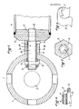
- the device according to FIG. 1 comprises a hollow spherical core 1 in which are made holes of small dimensions and a hole 3 of larger dimensions, capable of being closed by a shutter in the form of cap of which different embodiments are illustrated in FIGS. 5 to 8 under the references 115 a to 115 d .
- the number of holes 2 depends on the number of tubes such as 4 that one wishes to assemble to the core 1.
- the tubes 4 are provided with ends 5 at their ends in which a thread 6 is formed.
- a screw 7 has a central body 8 on the surface of which are longitudinal grooves 9.
- the screw 7 has on the other hand at one of its ends a thread 10 corresponding to the thread 6 and at its other end, a thread 11 of direction opposite thread 10.
- the thread 11 which, as will be seen below, is intended to work inside the core 1, preferably has a cross section greater than that of the thread 10. The latter can indeed be controlled much more easily.
- the screw 7 is engaged inside one of the holes 2 so that its thread 11 can be screwed onto a nut 12.
- a washer 13 is interposed between the nut 12 and the interior surface of the sphere 1.
- a ring 14 the inner surface of which is provided with grooves corresponding to the grooves 9 in the body of the screw, is engaged on this body so as to be able to drive it in rotation, for example using a wrench.
- the pin 15 is then removed and the thread 10 is screwed into the internal thread 6 by turning the screw 7 using the ring 14 by means of the grooves 9.
- the ends of the ring 14 come to bear on the one hand on the outer surface of the sphere 1, and on the other hand on the end piece 5, the two threads 10 and 11 are blocked, one in the internal thread 6 and the other in the nut 12, because that these threads are reversed.
- the tube 4 is thus firmly secured to the sphere 1.
- FIGS. 3 and 4 show a variant of the means for temporarily securing the ring 14 relative to the screw 7.
- a clip 16 is mounted on the ring 14 by pinching and has a projection 17 folded back towards the screw so as to engage in threads of the thread 10.
- the clip 16 is held on the clamping ring 14 as long as the thread 10 is not engaged in the internal thread 6. When this is done, the clip 7 is removed and the tightening is carried out as above.
- the sealing element is a curable mass 114 filling the interior cavity of the core and injected through a small injection port 105 made in the wall of the core 1. Besides its sealing function the mass 114 provides an additional function of blocking the internal locking nuts 12.
- the sealing element is a compressible annular seal 116 of frustoconical profile placed between frustoconical bearing surfaces facing the orifice 3 formed in the core and the shaped obturator cap 115c.
- two sealing elements are provided, namely on the one hand a curable base 114 filling the cavity of the core and, on the other hand, a compressible annular seal 116 also arranged between frustoconical surfaces facing the orifice 3 and the shutter 115d.
- the shutter 115a illustrated in FIG. 5 is secured to the core by being provided with a thread 117 in which engages a screw 118 introduced by a hole 2 diametrically opposite the orifice 3.
- a spacer 119 provided with a captive nut 120 in which is screwed a screw 121 engaged in a hole 122 provided for this purpose in the shutter 115b.
- FIG. 8 shows a variant of a shutter 115d, the inner face of which is secured to a screw 123 engaging by screwing in a nut 124, itself secured to a spacer 125.
- the shutter 115d constitutes in a way the head of the screw 123 and can be driven in rotation by an operating key (not shown) engaging in notches 126 formed for this purpose in the outer wall. shutter 115d.
- the grooves which allow the longitudinal sliding of the ring on the body of the screw while ensuring the rotational drive could possibly be replaced by one or more pins fixed to the body of the screw and cooperating with longitudinal slots in the ring.
Abstract
L'invention est relative à un dispositif pour tubes ou barres munis d'embouts taraudés. Il comprend un noyau creux (1) comportant une pluralité de trous (2, 3) et au moins deux vis (7) possèdant chacune un filetage (10, 11) à chacune de ses extrémités, chaque vis traversant un desdits trous (2) et ayant son filetage (11) intérieur au noyau vissé sur un écrou (12) et son filetage (10) extérieur vissé sur l'embout (9) d'un desdits tubes ou barres (4), l'un des trous (3) ayant des dimensions supérieures à celles des écrous pour permettre l'introduction des écrous dans ledit noyau, des moyens de serrage (14) étant prévus pour assurer le serrage de chaque vis sur l'embout correspondant.The invention relates to a device for tubes or bars provided with threaded ends. It comprises a hollow core (1) comprising a plurality of holes (2, 3) and at least two screws (7) each having a thread (10, 11) at each of its ends, each screw passing through one of said holes (2) and having its internal thread (11) at the core screwed onto a nut (12) and its external thread (10) screwed onto the end piece (9) of one of said tubes or bars (4), one of the holes (3 ) having dimensions greater than those of the nuts to allow the introduction of the nuts into said core, tightening means (14) being provided to ensure the tightening of each screw on the corresponding end piece.
Description
La présente invention concerne un dispositif d'assemblage d'un premier élément à un deuxième élément, tels que des tubes ou barres, munis d'embouts taraudés.The present invention relates to a device for assembling a first element to a second element, such as tubes or bars, provided with threaded ends.
On connaît déjà de tels dispositifs dans lesquels les extrémités d'une pluralité de tubes ou de barres sont réunies au niveua d'un noyau d'assemblage. Ces dispositifs connus présentent toutefois l'inconvénient que, pour permettre le vissage des extrémités des tubes, les noyaux doivent être de grande dimension, et par conséquent, lourds, onéreux et inesthétiques.Such devices are already known in which the ends of a plurality of tubes or bars are joined at the level of an assembly core. These known devices however have the drawback that, to allow the ends of the tubes to be screwed on, the cores must be large, and therefore heavy, expensive and unsightly.
La présente invention vise à pallier cet inconvénient.The present invention aims to overcome this drawback.
A cet effet, l'invention a tout d'abord pour objet un dispositif d'assemblage d'un premier élément à un deuxième élément muni d'un embout taraudé, comprenant une vis susceptible de coopérer avec ledit embout et munie d'une tête agencée pour être maintenue dans ledit premier élément, caractérisé par le fait qu'il comprend des moyens de serrage comprenant une bague, solidaire en rotation du corps de ladite vis et pouvant coulisser librement sur ledit corps.To this end, the invention firstly relates to a device for assembling a first element to a second element provided with a threaded end, comprising a screw capable of cooperating with said end piece and provided with a head arranged to be held in said first element, characterized in that it comprises clamping means comprising a ring, integral in rotation with the body of said screw and capable of sliding freely on said body.
L'invention a également pour objet un dispositif d'assemblage pour tubes ou barres munis d'embouts taraudés, caractérisé par le fait qu'il comprend un noyau creux comportant une pluralité de trous et au moins deux vis possédant chacune un filetage à chacune de ses extrémités, chaque vis traversant un desdits trous et ayant son filetage intérieur au noyau vissé sur un écrou et son filetage extérieur vissé sur l'embout d'un desdits tubes ou barres, l'un des trous ayant des dimensions supérieures à celles des écrous pour permettre l'introduction des écrous dans ledit noyau, des moyens de serrage étant prévus pour assurer le serrage de chaque vis sur l'embout correspondant.The invention also relates to an assembly device for tubes or bars provided with threaded ends, characterized in that it comprises a hollow core comprising a plurality of holes and at least two screws each having a thread at each of its ends, each screw passing through one of said holes and having its internal thread at the core screwed onto a nut and its external thread screwed onto the end of one of said tubes or bars, one of the holes having dimensions greater than those of the nuts to allow the introduction of the nuts into said core, tightening means being provided to ensure the tightening of each screw on the corresponding end piece.
Le fait d'utiliser une vis et un écrou séparés présente un certain nombre d'avantages.Using a separate screw and nut has a number of advantages.
Tout d'abord, le trou par lequel sont introduits les écrous ne doit avoir que des dimensions juste supérieures à ces écrous.First of all, the hole through which the nuts are introduced should only have dimensions just larger than these nuts.
La résistance mécanique du noyau n'en est donc que très peu diminuée.The mechanical resistance of the core is therefore only very slightly reduced.
Par ailleurs, il n'est pas nécessaire de prévoir des manipulations de la vis à l'intérieur du noyau. Celui-ci peut par conséquent être de faibles dimensions.Furthermore, it is not necessary to provide manipulations of the screw inside the core. This can therefore be small.
Les moyens de serrage peuvent comprendre par exemple une bague de serrage engagée sur le corps de la vis entre les deux filetages, ladite bague étant solidaire en rotation du corps mais pouvant coulisser librement sur lui.The clamping means may for example comprise a clamping ring engaged on the body of the screw between the two threads, said ring being integral in rotation with the body but being able to slide freely on it.
Le montage s'effectue alors en introduisant un écrou à l'intérieur du noyau, en faisant pénétrer par un des trous le filetage correspondant d'une des vis, à visser l'écrou sur ce filetage puis, à l'aide de la bague de serrage, à faire tourner la vis de manière à engager son autre filetage dans l'embout taraudé du tube ou de la barre.The assembly is then carried out by introducing a nut inside the core, by making penetrate by one of the holes the corresponding thread of one of the screws, to screw the nut on this thread then, using the ring tightening, turn the screw so as to engage its other thread in the threaded end of the tube or bar.
On peut de la sorte assembler au noyau deux ou plusieurs tubes ou barres.It is thus possible to assemble two or more tubes or bars to the core.
Dans un mode de réalisation particulier de l'invention, lorsque la vis est serrée, la bague a une de ses extrémités en appui sur la surface extérieure du noyau et son autre extrémité en appui sur ledit embout.In a particular embodiment of the invention, when the screw is tightened, the ring has one of its ends in abutment on the outer surface of the core and its other end in abutment on said endpiece.
On obtient ainsi une excellente résistance mécanique de la liaison entre le tube et le noyau du fait que la vis se trouve alors en traction entre l'écrou intérieur au noyau et l'embout, alors qu la bague se trouve en compression.Excellent mechanical resistance is thus obtained from the connection between the tube and the core because the screw is then in tension between the nut inside the core and the end piece, while the ring is in compression.
De manière à assurer le coulissement longitudinal de la bague sur le corps de la vis et l'entraînement en rotation, ce corps et la surface intérieure de la bague peuvent comporter des canelures longitudinales complémentaires.In order to ensure the longitudinal sliding of the ring on the body of the screw and the rotation drive, this body and the inner surface of the ring may include complementary longitudinal grooves.
Avantageusement, on peut prévoir des moyens amovibles pour empêcher le coulissement de la bague sur le corps de la vis.Advantageously, it is possible to provide removable means to prevent the sliding of the ring on the body of the screw.
Ces moyens ont deux fonctions. D'une part, ils empêchent la séparation de la bague et de la vis avant le montage, évitant en particulier la perte de la bague.These means have two functions. On the one hand, they prevent the separation of the ring and the screw before mounting, in particular preventing the loss of the ring.
Par ailleurs, ils permettent de présenter convenablement l'extrémité du filetage de la vis par rapport au début du taraudage de l'embout et facilite ainsi le début du vissage.Furthermore, they make it possible to present the end of the thread of the screw suitably relative to the start of the tapping of the end piece and thus facilitate the start of the screwing.
Ces moyens amovibles peuvent par exemple comprendre une cheville engagée à force dans un trou radial de la bague, et ayant son extrémité interne en appui sur le corps de la vis, ou encore comprendre un clip pincé sur la bague et muni d'une saillie engagée dans le filetage extérieur de la vis.These removable means can for example comprise a dowel forcibly engaged in a radial hole in the ring, and having its internal end in abutment on the body of the screw, or even include a clip pinched on the ring and provided with an engaged projection in the external thread of the screw.
Avantageusement, les deux filetages de chaque vis ont des sens opposés, de sorte que, lorsque l'on serre la vis sur l'embout, le serrage de la vis sur l'écrou en est augmenté.Advantageously, the two threads of each screw have opposite directions, so that, when the screw is tightened on the end piece, the tightening of the screw on the nut is increased.
Dans une forme de réalisation particulière de l'invention, le noyau est sensiblement sphèrique, mais d'autres formes peuvent bien entendu être envisagées.In a particular embodiment of the invention, the core is substantially spherical, but other forms can of course be envisaged.
Dans le cas où la structure assemblée est soumise à un environnement difficile pouvant entraîner des conséquences dommageables au niveau du noyau par suite de phénomènes de gel ou de corrosion, on peut avantageusement prévoir au moins un élément d'étanchéité rapporté apte à isoler de façon étanche vis-à-vis de l'extérieur la cavité intérieur du noyau.In the case where the assembled structure is subjected to a difficult environment which can lead to damaging consequences at the level of the core as a result of freezing or corrosion phenomena, it is possible to advantageously provide at least one attached sealing element capable of sealingly isolating the interior cavity of the core from the outside.
Dans un premier mode de réalisation, l'élément d'étanchéité est constitué par un joint annulaire compressible interposé entre les faces en regard de l'obturateur et de la paroi de l'orifice logeant celui-ci.In a first embodiment, the sealing element consists of a compressible annular seal interposed between the facing faces of the shutter and of the wall of the orifice housing the latter.
Dans un second mode de réalisation, l'élément d'étanchéité est constitué par une masse durcissable injectée par un orifice d'injection prévu à cet effet dans la paroi du noyau et remplissant au moins partiellement la cavité intérieure du noyau. Comme matériau durcissable, on peut citer par exemple le ciment ou les mousses expansibles, par exemple des mousses de polyuréthane à cellules fermées.In a second embodiment, the sealing element consists of a curable mass injected by an injection orifice provided for this purpose in the wall of the core and at least partially filling the interior cavity of the core. As curable material, there may be mentioned, for example, cement or expandable foams, for example closed cell polyurethane foams.
Le matériau d'étanchéité peut être injecté directement dans la cavité ou à l'intérieur d'une poche déformable mise en place dans la cavité.The sealing material can be injected directly into the cavity or inside a deformable pocket placed in the cavity.
On peut également selon l'invention réaliser l'étanchéité en associant l'élément d'étanchéité du premier mode de réalisation et l'élément d'étanchéité selon le second mode de réalisation.According to the invention, it is also possible to achieve sealing by combining the sealing element of the first embodiment and the sealing element according to the second embodiment.
On décrira maintenant à titre d'exemple non limitatif des modes de réalisation particulier de l'invention en référence aux dessins schématiques annexés dans lesquels :
- - la figure 1 est une vue en coupe d'un premier dispositif selon l'invention sur lequel un seul tube est monté,
- - la figure 2 est une vue en coupe selon la ligne II-II de la figure 1,
- - la figure 3 est une vue en perspective d'un clip selon l'invention,
- - la figure 4 est une vue partielle en coupe montrant le clip de la figure 3 monté sur le dispositif.
- - la figure 5 illustre en coupe une deuxième forme de réalisation de l'invention, dans laquelle les vis de liaison n'ont pas été représentés,
- - la figure 6 est une vue analogue à la figure 5 illustrant une autre forme de réalisation,
- - la figure 7 est une vue analogue illustrant une autre forme de réalisation, et
- - la figure 8 est une vue analogue représentant une autre forme de réalisation.
- FIG. 1 is a sectional view of a first device according to the invention on which a single tube is mounted,
- FIG. 2 is a sectional view along the line II-II of FIG. 1,
- FIG. 3 is a perspective view of a clip according to the invention,
- - Figure 4 is a partial sectional view showing the clip of Figure 3 mounted on the device.
- FIG. 5 illustrates in section a second embodiment of the invention, in which the connecting screws have not been shown,
- FIG. 6 is a view similar to FIG. 5 illustrating another embodiment,
- FIG. 7 is a similar view illustrating another embodiment, and
- - Figure 8 is a similar view showing another embodiment.
Le dispositif selon la figure 1 comprend un noyau sphèrique creux 1 dans lequel sont ménagés des trous de petites dimensions et un trou 3 de plus grandes dimensions, apte à être fermé par un obturateur en forme de calotte dont différentes formes d'exécution sont illustrées aux figures 5 à 8 sous les références 115a à 115 d.The device according to FIG. 1 comprises a hollow spherical core 1 in which are made holes of small dimensions and a
Le nombre de trous 2 dépend du nombre de tubes tels que 4 que l'on souhaite assembler au noyau 1.The number of
Les tubes 4 sont munis à leurs extrémités d'embouts 5 dans lesquels est formé un taraudage 6.The tubes 4 are provided with ends 5 at their ends in which a
Une vis 7 comporte un corps central 8 à la surface duquel sont formées des canelures longitudinales 9. La vis 7 possède d'autre part à une de ses extrémités un filetage 10 correspondant au taraudage 6 et à son autre extrémité, un filetage 11 de sens opposé au filetage 10.A
Le filetage 11 qui, comme on le verra ci-après, est destiné à travailler à l'intérieur du noyau 1, a de préférence une section supérieure à celle du filetage 10. Ce dernier peut en effet être contrôlé beaucoup plus facilement.The
La vis 7 est engagée à l'intérieur d'un des trous 2 de sorte que son filetage 11 puisse être vissé sur un écrou 12. Une rondelle 13 est interposée entre l'écrou 12 et la surface intérieure de la sphère 1.The
Une bague 14 dont la surface intérieure est munie de canelures correspondant aux canelures 9 du corps de la vis est engagée sur ce corps de manière à pouvoir l'entraîner en rotation, par exemple à l'aide d'une clé.A
Une cheville 15, par exemple en matière plastique, est engagée à force dans un trou radial de la bague jusqu'à venir en contact avec le corps 8 de la vis 7 pour empêcher temporairement la bague 14 de coulisser par rapport à cette vis.A
La rondelle 13 et l'écrou 12 ayant été introduits dans la sphère 1 par le trou 3 dont les dimensions sont prévues à cet effet, la vis 7 est vissée sur l'écrou 11 et l'extrémité du filetage 10 est engagée dans le taraudage 6 en s'aidant de la bague 14 qui est encore solidaire de la vis.The
La cheville 15 est alors retirée et le filetage 10 est vissé dans le taraudage 6 en faisant tourner la vis 7 à l'aide de la bague 14 par l'intermédiaire des canelures 9. Lorsque les extrémités de la bague 14 viennent en appui d'une part sur la surface extérieure de la sphère 1, et d'autre part sur l'embout 5, les deux filetages 10 et 11 sont bloqués, l'un dans le taraudage 6 et l'autre dans l'écrou 12, du fait que ces filetages sont inversés.The
Le tube 4 est ainsi fermement solidarisé à la sphère 1.The tube 4 is thus firmly secured to the sphere 1.
D'autres tubes 4 peuvent alors être assemblés au noyau sphèrique 1 au niveau des autres trous 2.Other tubes 4 can then be assembled to the spherical core 1 at the level of the
Les figures 3 et 4 représentent une variante des moyens de solidarisation temporaire de la bague 14 par rapport à la vis 7.FIGS. 3 and 4 show a variant of the means for temporarily securing the
Un clip 16 est monté sur la bague 14 par pincement et possède une saillie 17 rabattue vers la vis de manière à venir s'engager dans des filets du filetage 10. Le clip 16 est maintenu sur la bague de serrage 14 tant que le filetage 10 n'est pas engagé dans le taraudage 6. Lorsque ceci est effectué, le clip 7 est retiré et le serrage s'effectue comme précédemment.A
Dans les formes de réalisations illustrées aux figures 5 et 6, l'élément d'étanchéité est une masse durcissable 114 remplissant la cavité intérieure du noyau et injectée par un orifice d'injection de faibles dimensions 105 réalisé dans la paroi du noyau 1. Outre sa fonction d'étanchéité la masse 114 assure une fonction supplémentaire de blocage des écrous intérieurs de blocage 12.In the embodiments illustrated in FIGS. 5 and 6, the sealing element is a
Dans le mode de réalisation de la figure 7, l'élément d'étanchéité est un joint annulaire compressible 116 de profil tronconique mis en place entre des portées tronconiques en regard de l'orifice 3 ménagé dans le noyau et de l'obturateur en forme de calotte 115c.In the embodiment of FIG. 7, the sealing element is a compressible
Dans le mode de réalisation de la figure 8, il est prévu deux éléments d'étanchéité, à savoir d'une part une mase durcissable 114 remplissant la cavité du noyau et, d'autre part, un joint annulaire compressible 116 disposé également entre des portées tronconiques en regard de l'orifice 3 et de l'obturateur 115d.In the embodiment of FIG. 8, two sealing elements are provided, namely on the one hand a
L'obturateur 115a illustré à la figure 5 est solidarisé du noyau en étant muni d'un taraudage 117 dans lequel s'engage une vis 118 introduite par un trou 2 diamétralement opposé à l'orifice 3.The
Dans le mode de réalisation de la figure 6, il est prévu pour immobiliser l'obturateur 115b, une entretoise 119 munie d'un écrou prisonnier 120 dans lequel est vissée une vis 121 engagée dans un trou 122 prévu à cet effet dans l'obturateur 115b.In the embodiment of Figure 6, there is provided to immobilize the
Le même montage est prévu pour l'obturateur 115c de la forme de réalisation de la figure 7.The same assembly is provided for the shutter 115c of the embodiment of FIG. 7.
On voit à la figure 8, une variante d'obturateur 115d dont la face intérieure est solidaire d'une vis 123 s'engageant par vissage dans un écrou 124, lui-même solidaire d'une entretoise 125.FIG. 8 shows a variant of a
Dans ce mode de réalisation, l'obturateur 115d constitue en quelque sorte la tête de la vis 123 et peut être entraîné en rotation par une clé de manoeuvre (non représentée) s'engageant dans des encoches 126 ménagées à cet effet dans la paroi extérieure de l'obturateur 115d.In this embodiment, the
Diverses variantes et modifications peuvent bien entendu être apportées à la description qui précède sans sortir pour autant du cadre ni de l'esprit de l'invention.Various variants and modifications can of course be made to the above description without departing from the scope or the spirit of the invention.
C'est ainsi, en particulier, que les cannelures qui permettent le coulissement longitudinal de la bague sur le corps de la vis tout en assurant l'entraînement en rotation pourraient éventuellement être remplacées par un ou plusieurs tétons fixés au corps de la vis et coopérant avec des fentes longitudinales de la bague.Thus, in particular, the grooves which allow the longitudinal sliding of the ring on the body of the screw while ensuring the rotational drive could possibly be replaced by one or more pins fixed to the body of the screw and cooperating with longitudinal slots in the ring.
Claims (14)
Applications Claiming Priority (4)
| Application Number | Priority Date | Filing Date | Title |
|---|---|---|---|
| FR8517055A FR2590332B1 (en) | 1985-11-19 | 1985-11-19 | ASSEMBLY DEVICE FOR TUBES OR BARS |
| FR8517055 | 1985-11-19 | ||
| FR8519308 | 1985-12-27 | ||
| FR8519308A FR2592446B1 (en) | 1985-12-27 | 1985-12-27 | ASSEMBLY DEVICE FOR TUBES OR BARS WITH TAPPED MOUTHPIECES |
Publications (1)
| Publication Number | Publication Date |
|---|---|
| EP0228930A1 true EP0228930A1 (en) | 1987-07-15 |
Family
ID=26224829
Family Applications (1)
| Application Number | Title | Priority Date | Filing Date |
|---|---|---|---|
| EP86402564A Withdrawn EP0228930A1 (en) | 1985-11-19 | 1986-11-19 | Device for assembling tubes or rods |
Country Status (2)
| Country | Link |
|---|---|
| US (1) | US4806041A (en) |
| EP (1) | EP0228930A1 (en) |
Cited By (3)
| Publication number | Priority date | Publication date | Assignee | Title |
|---|---|---|---|---|
| WO1990006449A1 (en) * | 1988-12-05 | 1990-06-14 | Hassid Jean Pierre | System for the high-speed mutual assembly of two elements and process for its implementation |
| GB2281368A (en) * | 1993-08-21 | 1995-03-01 | Mark Anthony Dennis | Concealed fixing device |
| GB2303190A (en) * | 1995-07-07 | 1997-02-12 | Terence Philip Bourne | Frameworks formed of rods and nodal connectors |
Families Citing this family (8)
| Publication number | Priority date | Publication date | Assignee | Title |
|---|---|---|---|---|
| US5473852A (en) * | 1988-12-22 | 1995-12-12 | British Technology Group Ltd. | Mechanical devices and structures |
| DE29800939U1 (en) * | 1998-01-21 | 1998-03-05 | Festo Ag & Co | Connecting device |
| DE10118150B4 (en) * | 2001-04-11 | 2008-10-02 | Hewi Heinrich Wilke Gmbh | fastening device |
| TR200802137A1 (en) * | 2008-03-31 | 2009-03-23 | Aysan Nezi̇h | Space roof fasteners. |
| FR3014967B1 (en) * | 2013-12-13 | 2016-07-29 | Airbus Operations Sas | DEVICE FOR FIXING AN OBJECT BY LIQUID INJECTION |
| DE102016002895A1 (en) * | 2016-03-09 | 2017-09-14 | Boris Pushkin | Bar element for a scaffold made of prefabricated components |
| TWI770599B (en) * | 2020-09-04 | 2022-07-11 | 賴祥瑞 | Modular connection device |
| CN113216381B (en) * | 2021-03-29 | 2022-08-12 | 中建一局钢结构工程有限公司 | Simplified net rack bolt-ball connection node and construction method thereof |
Citations (8)
| Publication number | Priority date | Publication date | Assignee | Title |
|---|---|---|---|---|
| GB1189235A (en) * | 1968-01-29 | 1970-04-22 | Peter Benjamin Wright Crighton | Improvements in or relating to Connecting Devices |
| DE2426973A1 (en) * | 1974-06-04 | 1975-12-11 | Armin Mylaeus | KIT FOR CREATING FRAMEWORK |
| FR2273914A1 (en) * | 1974-06-06 | 1976-01-02 | Mannesmann Roehren Werke Ag | THREE-DIMENSIONAL FRAMEWORK |
| DE2736635B1 (en) * | 1977-08-13 | 1978-10-05 | Mero Raumstruktur Gmbh & Co | Screw connection between the pipe rods and a junction piece of junction connections of a space framework |
| FR2434903A1 (en) * | 1978-09-04 | 1980-03-28 | Martinez Apezteguia Juan | Node and bar prefabricated space frame - has bar connector with two opposite threads and tightening nut |
| FR2439935A1 (en) * | 1978-10-25 | 1980-05-23 | Bretagne Ste Metallurg | Prefabricated roof framework - has tubular supports bolted onto hollow spheres at various angles |
| FR2474641A1 (en) * | 1980-01-28 | 1981-07-31 | Allegheny Ludlum Ind Inc | Spherical connector for tubular sections - has integral, radial pipe receiving outlets in housing with bevel for weld |
| EP0081608A1 (en) * | 1981-12-16 | 1983-06-22 | Pfeifer Seil- und Hebetechnik GmbH & Co. | Space frame |
Family Cites Families (12)
| Publication number | Priority date | Publication date | Assignee | Title |
|---|---|---|---|---|
| GB591570A (en) * | 1945-05-14 | 1947-08-21 | Spencer Alfred Mason | Improvements in or relating to means for drawing and securing together tubes or other tubular objects |
| US1914260A (en) * | 1930-12-04 | 1933-06-13 | Kennedy Valve Mfg Co | Valve |
| BE570158A (en) * | 1958-05-09 | |||
| US4027449A (en) * | 1973-01-30 | 1977-06-07 | Alcalde Cilveti Francisco Javi | System for constructing spatial structures |
| AT339094B (en) * | 1974-02-20 | 1977-09-26 | Frantl Conprojekt | NODE CONNECTION FOR FRAMEWORKS |
| DE2457674A1 (en) * | 1974-12-06 | 1976-06-10 | Bodner Wolf M | Angle connecting joint for space frameworks - spherical shell has several slots on different diameters and connecting struts |
| US4129206A (en) * | 1976-05-24 | 1978-12-12 | Coors Container Company | Container rotating means in apparatus for curing inks and decorative coatings |
| US4161088A (en) * | 1977-11-11 | 1979-07-17 | Gugliotta Paul F | Pipe-and-ball truss array |
| US4313687A (en) * | 1978-09-05 | 1982-02-02 | Juan Martinez Apeztegui | Prefabricated spatial structure |
| FR2452628A1 (en) * | 1979-03-27 | 1980-10-24 | Chateau Stephane Du | ASSEMBLY OF BARS FOR CROSSLINKED STRUCTURES OF METAL FRAMES |
| US4666326A (en) * | 1982-09-11 | 1987-05-19 | Metal Bond (Technology) Limited | Reinforcing bar coupling system |
| US4692054A (en) * | 1985-08-26 | 1987-09-08 | Northwest Design Products, Inc. | Connector system for structural framework |
-
1986
- 1986-11-19 US US06/932,275 patent/US4806041A/en not_active Expired - Fee Related
- 1986-11-19 EP EP86402564A patent/EP0228930A1/en not_active Withdrawn
Patent Citations (8)
| Publication number | Priority date | Publication date | Assignee | Title |
|---|---|---|---|---|
| GB1189235A (en) * | 1968-01-29 | 1970-04-22 | Peter Benjamin Wright Crighton | Improvements in or relating to Connecting Devices |
| DE2426973A1 (en) * | 1974-06-04 | 1975-12-11 | Armin Mylaeus | KIT FOR CREATING FRAMEWORK |
| FR2273914A1 (en) * | 1974-06-06 | 1976-01-02 | Mannesmann Roehren Werke Ag | THREE-DIMENSIONAL FRAMEWORK |
| DE2736635B1 (en) * | 1977-08-13 | 1978-10-05 | Mero Raumstruktur Gmbh & Co | Screw connection between the pipe rods and a junction piece of junction connections of a space framework |
| FR2434903A1 (en) * | 1978-09-04 | 1980-03-28 | Martinez Apezteguia Juan | Node and bar prefabricated space frame - has bar connector with two opposite threads and tightening nut |
| FR2439935A1 (en) * | 1978-10-25 | 1980-05-23 | Bretagne Ste Metallurg | Prefabricated roof framework - has tubular supports bolted onto hollow spheres at various angles |
| FR2474641A1 (en) * | 1980-01-28 | 1981-07-31 | Allegheny Ludlum Ind Inc | Spherical connector for tubular sections - has integral, radial pipe receiving outlets in housing with bevel for weld |
| EP0081608A1 (en) * | 1981-12-16 | 1983-06-22 | Pfeifer Seil- und Hebetechnik GmbH & Co. | Space frame |
Cited By (6)
| Publication number | Priority date | Publication date | Assignee | Title |
|---|---|---|---|---|
| WO1990006449A1 (en) * | 1988-12-05 | 1990-06-14 | Hassid Jean Pierre | System for the high-speed mutual assembly of two elements and process for its implementation |
| GB2281368A (en) * | 1993-08-21 | 1995-03-01 | Mark Anthony Dennis | Concealed fixing device |
| GB2281368B (en) * | 1993-08-21 | 1996-06-12 | Mark Anthony Dennis | Concealed fixing device |
| US5613793A (en) * | 1993-08-21 | 1997-03-25 | Dennis; Mark A. | Concealed fixing device |
| GB2303190A (en) * | 1995-07-07 | 1997-02-12 | Terence Philip Bourne | Frameworks formed of rods and nodal connectors |
| GB2303190B (en) * | 1995-07-07 | 1999-11-10 | Terence Philip Bourne | Constructional apparatus |
Also Published As
| Publication number | Publication date |
|---|---|
| US4806041A (en) | 1989-02-21 |
Similar Documents
| Publication | Publication Date | Title |
|---|---|---|
| EP0793024B1 (en) | Device for assembling and locking telescopic tubes | |
| FR2475812A1 (en) | ELECTRICAL CONNECTING DEVICE COMPRISING AN IMPROVED MECHANISM OPPOSING THE DISASSEMBLY | |
| FR2694791A1 (en) | Safety bolts, nuts and bolt body. | |
| EP0228930A1 (en) | Device for assembling tubes or rods | |
| FR2534646A1 (en) | PLASTIC COLLAR FOR TUBES | |
| FR2976987A1 (en) | Assembling device for fixing seat belt return strap on lining part of passenger compartment of vehicle, has screw whose surface exerts constraint on retaining unit to maintain unit in locking position when device is in service configuration | |
| FR2810087A1 (en) | Insert for implanting pipe connection in tapped housing comprises body which fits against tapped section, on which rings with anchor lugs are mounted, each lug being compressible from position above outer surface of insert to below it | |
| WO1993021448A1 (en) | Telescoping tubular assembly | |
| EP0402198B1 (en) | Locking-nut assembly | |
| BE1000113A5 (en) | Fitting pipe. | |
| EP0574357A1 (en) | Assembling device through clamping an elastic compressible piece | |
| EP1605195B1 (en) | Pipe coupling system and associated method of assembly | |
| EP0581637B1 (en) | Cock with cylindrical plug | |
| EP0002405B1 (en) | Device for positively locking a screw in a threaded bore | |
| FR2799515A1 (en) | GAME RETRIEVAL SYSTEM FOR ATTACHING TWO PIECES TO EACH OTHER USING A SCREW TYPE FASTENER | |
| FR2590332A1 (en) | Assembly device for tubes or bars | |
| EP0207833B1 (en) | Threaded stud comprising a torque-limiting means | |
| EP3106587A1 (en) | Device for fixing an object immersed in an underwater pool | |
| FR2595122A1 (en) | Assembly device for tubes or bars | |
| FR2596473A1 (en) | Fastening device | |
| FR2620179A1 (en) | DEVICE FOR CONNECTING SCREWS BETWEEN TWO PIECES WITH POSSIBILITY OF ADJUSTING THE SPACING BETWEEN THEM | |
| EP0972955A2 (en) | Nut fixing device | |
| FR2547369A1 (en) | Wall fixing device | |
| EP0572296B1 (en) | System for the chemical sealing of or fastening element in a hollow material | |
| WO1998053214A1 (en) | Device for fixing an element to a thin support |
Legal Events
| Date | Code | Title | Description |
|---|---|---|---|
| PUAI | Public reference made under article 153(3) epc to a published international application that has entered the european phase |
Free format text: ORIGINAL CODE: 0009012 |
|
| AK | Designated contracting states |
Kind code of ref document: A1 Designated state(s): DE ES GB IT NL |
|
| 17P | Request for examination filed |
Effective date: 19880106 |
|
| 17Q | First examination report despatched |
Effective date: 19890216 |
|
| STAA | Information on the status of an ep patent application or granted ep patent |
Free format text: STATUS: THE APPLICATION IS DEEMED TO BE WITHDRAWN |
|
| 18D | Application deemed to be withdrawn |
Effective date: 19910126 |