EP0078076A2 - Schneider für Bänder - Google Patents
Schneider für Bänder Download PDFInfo
- Publication number
- EP0078076A2 EP0078076A2 EP82201280A EP82201280A EP0078076A2 EP 0078076 A2 EP0078076 A2 EP 0078076A2 EP 82201280 A EP82201280 A EP 82201280A EP 82201280 A EP82201280 A EP 82201280A EP 0078076 A2 EP0078076 A2 EP 0078076A2
- Authority
- EP
- European Patent Office
- Prior art keywords
- strip
- label
- knife
- carrier
- wheel
- Prior art date
- Legal status (The legal status is an assumption and is not a legal conclusion. Google has not performed a legal analysis and makes no representation as to the accuracy of the status listed.)
- Withdrawn
Links
Images

Classifications
-
- B—PERFORMING OPERATIONS; TRANSPORTING
- B26—HAND CUTTING TOOLS; CUTTING; SEVERING
- B26D—CUTTING; DETAILS COMMON TO MACHINES FOR PERFORATING, PUNCHING, CUTTING-OUT, STAMPING-OUT OR SEVERING
- B26D7/00—Details of apparatus for cutting, cutting-out, stamping-out, punching, perforating, or severing by means other than cutting
- B26D7/01—Means for holding or positioning work
- B26D7/018—Holding the work by suction
-
- B—PERFORMING OPERATIONS; TRANSPORTING
- B26—HAND CUTTING TOOLS; CUTTING; SEVERING
- B26D—CUTTING; DETAILS COMMON TO MACHINES FOR PERFORATING, PUNCHING, CUTTING-OUT, STAMPING-OUT OR SEVERING
- B26D7/00—Details of apparatus for cutting, cutting-out, stamping-out, punching, perforating, or severing by means other than cutting
- B26D7/08—Means for treating work or cutting member to facilitate cutting
-
- B—PERFORMING OPERATIONS; TRANSPORTING
- B65—CONVEYING; PACKING; STORING; HANDLING THIN OR FILAMENTARY MATERIAL
- B65C—LABELLING OR TAGGING MACHINES, APPARATUS, OR PROCESSES
- B65C3/00—Labelling other than flat surfaces
- B65C3/06—Affixing labels to short rigid containers
- B65C3/08—Affixing labels to short rigid containers to container bodies
- B65C3/14—Affixing labels to short rigid containers to container bodies the container being positioned for labelling with its centre-line vertical
- B65C3/16—Affixing labels to short rigid containers to container bodies the container being positioned for labelling with its centre-line vertical by rolling the labels onto cylindrical containers, e.g. bottles
-
- B—PERFORMING OPERATIONS; TRANSPORTING
- B65—CONVEYING; PACKING; STORING; HANDLING THIN OR FILAMENTARY MATERIAL
- B65C—LABELLING OR TAGGING MACHINES, APPARATUS, OR PROCESSES
- B65C9/00—Details of labelling machines or apparatus
- B65C9/08—Label feeding
-
- B—PERFORMING OPERATIONS; TRANSPORTING
- B65—CONVEYING; PACKING; STORING; HANDLING THIN OR FILAMENTARY MATERIAL
- B65C—LABELLING OR TAGGING MACHINES, APPARATUS, OR PROCESSES
- B65C9/00—Details of labelling machines or apparatus
- B65C9/08—Label feeding
- B65C9/18—Label feeding from strips, e.g. from rolls
- B65C9/1803—Label feeding from strips, e.g. from rolls the labels being cut from a strip
- B65C9/1815—Label feeding from strips, e.g. from rolls the labels being cut from a strip and transferred by suction means
- B65C9/1819—Label feeding from strips, e.g. from rolls the labels being cut from a strip and transferred by suction means the suction means being a vacuum drum
-
- B—PERFORMING OPERATIONS; TRANSPORTING
- B65—CONVEYING; PACKING; STORING; HANDLING THIN OR FILAMENTARY MATERIAL
- B65C—LABELLING OR TAGGING MACHINES, APPARATUS, OR PROCESSES
- B65C9/00—Details of labelling machines or apparatus
- B65C9/26—Devices for applying labels
- B65C9/30—Rollers
-
- B—PERFORMING OPERATIONS; TRANSPORTING
- B65—CONVEYING; PACKING; STORING; HANDLING THIN OR FILAMENTARY MATERIAL
- B65C—LABELLING OR TAGGING MACHINES, APPARATUS, OR PROCESSES
- B65C9/00—Details of labelling machines or apparatus
- B65C9/26—Devices for applying labels
- B65C9/34—Flexible bands
-
- B—PERFORMING OPERATIONS; TRANSPORTING
- B26—HAND CUTTING TOOLS; CUTTING; SEVERING
- B26D—CUTTING; DETAILS COMMON TO MACHINES FOR PERFORATING, PUNCHING, CUTTING-OUT, STAMPING-OUT OR SEVERING
- B26D7/00—Details of apparatus for cutting, cutting-out, stamping-out, punching, perforating, or severing by means other than cutting
- B26D7/08—Means for treating work or cutting member to facilitate cutting
- B26D2007/082—Guiding or pushing a web into a favorable position by deflector means
-
- B—PERFORMING OPERATIONS; TRANSPORTING
- B65—CONVEYING; PACKING; STORING; HANDLING THIN OR FILAMENTARY MATERIAL
- B65C—LABELLING OR TAGGING MACHINES, APPARATUS, OR PROCESSES
- B65C9/00—Details of labelling machines or apparatus
- B65C9/08—Label feeding
- B65C9/18—Label feeding from strips, e.g. from rolls
- B65C9/1803—Label feeding from strips, e.g. from rolls the labels being cut from a strip
- B65C2009/1834—Details of cutting means
- B65C2009/1857—Details of cutting means two co-acting knifes
- B65C2009/1861—Details of cutting means two co-acting knifes whereby one knife remains stationary
-
- Y—GENERAL TAGGING OF NEW TECHNOLOGICAL DEVELOPMENTS; GENERAL TAGGING OF CROSS-SECTIONAL TECHNOLOGIES SPANNING OVER SEVERAL SECTIONS OF THE IPC; TECHNICAL SUBJECTS COVERED BY FORMER USPC CROSS-REFERENCE ART COLLECTIONS [XRACs] AND DIGESTS
- Y10—TECHNICAL SUBJECTS COVERED BY FORMER USPC
- Y10T—TECHNICAL SUBJECTS COVERED BY FORMER US CLASSIFICATION
- Y10T156/00—Adhesive bonding and miscellaneous chemical manufacture
- Y10T156/12—Surface bonding means and/or assembly means with cutting, punching, piercing, severing or tearing
- Y10T156/1317—Means feeding plural workpieces to be joined
- Y10T156/1322—Severing before bonding or assembling of parts
- Y10T156/1339—Delivering cut part in sequence to serially conveyed articles
-
- Y—GENERAL TAGGING OF NEW TECHNOLOGICAL DEVELOPMENTS; GENERAL TAGGING OF CROSS-SECTIONAL TECHNOLOGIES SPANNING OVER SEVERAL SECTIONS OF THE IPC; TECHNICAL SUBJECTS COVERED BY FORMER USPC CROSS-REFERENCE ART COLLECTIONS [XRACs] AND DIGESTS
- Y10—TECHNICAL SUBJECTS COVERED BY FORMER USPC
- Y10T—TECHNICAL SUBJECTS COVERED BY FORMER US CLASSIFICATION
- Y10T156/00—Adhesive bonding and miscellaneous chemical manufacture
- Y10T156/17—Surface bonding means and/or assemblymeans with work feeding or handling means
- Y10T156/1702—For plural parts or plural areas of single part
- Y10T156/1744—Means bringing discrete articles into assembled relationship
- Y10T156/1768—Means simultaneously conveying plural articles from a single source and serially presenting them to an assembly station
- Y10T156/1771—Turret or rotary drum-type conveyor
- Y10T156/1773—For flexible sheets
-
- Y—GENERAL TAGGING OF NEW TECHNOLOGICAL DEVELOPMENTS; GENERAL TAGGING OF CROSS-SECTIONAL TECHNOLOGIES SPANNING OVER SEVERAL SECTIONS OF THE IPC; TECHNICAL SUBJECTS COVERED BY FORMER USPC CROSS-REFERENCE ART COLLECTIONS [XRACs] AND DIGESTS
- Y10—TECHNICAL SUBJECTS COVERED BY FORMER USPC
- Y10T—TECHNICAL SUBJECTS COVERED BY FORMER US CLASSIFICATION
- Y10T83/00—Cutting
- Y10T83/323—With means to stretch work temporarily
-
- Y—GENERAL TAGGING OF NEW TECHNOLOGICAL DEVELOPMENTS; GENERAL TAGGING OF CROSS-SECTIONAL TECHNOLOGIES SPANNING OVER SEVERAL SECTIONS OF THE IPC; TECHNICAL SUBJECTS COVERED BY FORMER USPC CROSS-REFERENCE ART COLLECTIONS [XRACs] AND DIGESTS
- Y10—TECHNICAL SUBJECTS COVERED BY FORMER USPC
- Y10T—TECHNICAL SUBJECTS COVERED BY FORMER US CLASSIFICATION
- Y10T83/00—Cutting
- Y10T83/465—Cutting motion of tool has component in direction of moving work
- Y10T83/4766—Orbital motion of cutting blade
- Y10T83/4795—Rotary tool
- Y10T83/4847—With cooperating stationary tool
Definitions
- Such equipment usually includes a drum upon which the label is secured and which moves the label into engagement with the outer surface of the container.
- the label adheres to the container and is subsequently wrapped around the container by rolling the container along a fixed surface.
- This invention relates to cutter assemblies, one field of use of which is in labelling equipment.
- a cutter assembly to-sever sheets of material from a strip moving along a predetermined path, comprises a fixed support, a first knife element attached to said fixed support to extend transverse to said strip, a rotatable knife carrier mounted for rotation about a first axis, a second knife element attached to said rotatable knife carrier for movement therewith, drive means to rotate said rotatable knife carrier about said first axis and move said second knife element past said first knife element to produce a cutting action, said knife elements being inclined to one another in a plane containing the direction of travel of said second knife element to provide progressive severing of said strip in a direction transverse to the strip, characterised by cam means associated with said rotatable knife carrier and movable into said path to engage said strip, and also movable during a latter part of said cutting action out of said path to disengage said strip, whereby tension is removed from the portion of the strip being severed during the latter part of the cutting action.
- the labelling equipment shown is also the subject of our European Patent Application No. 79302772.3 (Specification No. 0 018 457 Al).
- the drawings illustrate labelling equipment capable of handling a strip of labels supplied on a spool, severing these labels individually, handling the labels and then applying them to bottles which are controlled and fed through the labelling equipment.
- the equipment is capable of use with various sizes of bottles, it is particularly designed for large bottles or other containers, having cylindrical portions for receiving wrap-around labels. These labels tend to be unwieldy and therefore difficult to handle. Also, because of the length of the labels they tend to buckle or apply unevenly with unacceptable results.
- the present equipment controls the labels and applies them to the bottles while maintaining some tension in the labels. As a result the labels are applied evenly and positively to the bottles or containers.
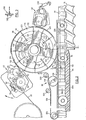
- FIG. 1 illustrates a preferred embodiment of labelling equipment 20 for use in applying wrap-around labels to a cylindrical portion of large plastic bottles.
- Labels in the form of a strip or web 22 are fed from a spool 24 to meet individually with bottles 26, 28 which are initially fed-to the equipment by a conveyor 30.
- the bottles meet a separator 32 which allows them to be moved individually by a bottle feeder 34 to a delivery position where each bottle receives a label from a label carrier 36.
- the bottle is then controlled by a bottle drive system 38 which rolls the bottle to receive the label and then dispatches the bottle out of the equipment.
- the strip 22 of labels is drawn by a label feeder assembly 40 which also includes a cutting head as will be described later. As the labels leave the feeder assembly 40 they are attached individually to the label carrier using a pneumatic vacuum system in the carrier 36. The labels then pass a glue applicator assembly 42 before being applied to bottles.
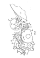
- FIG. 2 The general arrangement can also be seen in Figure 2 (the positions reached by bottles in Figure 2 being slightly different from the positions shown in Figure 1).
- a label 129 at an end of the strip 22 has been captured by label carrier 36, and preceding labels 44, 46 are attached to the carrier under the influence of the vacuum system as will be described.
- a label 48 precedes label 46 and has almost completely separated from the carrier 36 in the course of application onto a bottle 50.
- the peripheral speed of the portion of the label carrier 36 which receives the labels is slightly greater than the linear speed of the strip 22 to maintain some tension in the label as it transfers from the label feeder assembly 40 to the label carrier 36.
- the bottle drive system 38 is arranged to move the periphery of the bottle slightly faster than the label is moving with the carrier 36. This again ensures tension in the label as it is transferred from the carrier 36 to the bottle 50.
- label feeder assembly 40 will be described in detail before then describing the label carrier 36 and bottle drive system 38. Other parts of the equipment will be described where they relate to the feeder assembly, label carrier, and drive system.
- the strip is also guided by idlers 66, 68 which both tend to remove any natural curl from the labels and also ensure that the strip is in good contact with the main roll 52 before the strip meets the pinch roll 54.
- the strip passes from the main roll 52 through a cutter assembly 70 and into engagement with the periphery of the carrier 36 where it is held by vacuum pads as will be described below. Because of the greater peripheral speed of the carrier 36, the strip slips relative to the carrier so that it is under tension.
- the strip is moved from the main roll 52 into a position for severing into individual labels by a cutter assembly 70.
- This assembly consists of a stationary portion 72 and a rotating cutter head 74.
- the stationary portion 72 includes a blade 76 attached by screws 78 to a fixed bracket 80.
- the blade 76 can be aligned with a further blade 82 in a notched roll 84 using adjusting screws 86 before tightening screws 78 completely.
- the blade 82 is held in the notched roll 84 by screws 86a.
- the arrangement of the blades 76 and 82 is such that the strip is cut progressively across the width of the strip as indicated in Figure 5.
- the blade 76 is inclined to a vertical axis (i.e. an axis from bottom to top of Figure 5) whereas the blade 82 is vertical.
- the strip is being cut at a point 88 and has already been cut as far as that point running from the top to the bottom of the strip 22.
- the inclination of the blade 76 to the vertical axis ensures a square edge is cut as the label passes through the cutter assembly 70 so that it is not necessary to interrupt movement of the label whilst it is being cut.
- a cam lobe 85 is attached to the notched roll 84 and is positioned so that its peripheral surface 87 engages the strip 22 as it moves past the stationary blade 76. That is to say, the peripheral surface 87 and the blade 82 are located substantially equidistant from the axis of the roll 84. As may best be seen in Figure 4, the strip 22 is deflected in its path so that the effective distance between the stationary blade 76 and the point of engagement of the strip with the carrier 36 is increased. Since the strip is firmly held by pinch wheel 54 and main roll 52, the strip will slide relative to the periphery of the carrier 36.
- the cam lobe 85 moves out of the path of the strip 22 so that there is a temporary slack in the strip 22.
- the cam lobe 85 is positioned so as to disengage the strip 22 as the blades 76, 82 complete the cut. Since the tension is momentarily released from the strip, the tendency to tear the label from the strip is reduced.
- the path of the strip may be modified so that the cam engages the strip over a reduced arc, provided that sufficient slack is created in the label to permit the cut to be completed before the difference in speed between the carrier 36 and the main roll 52 again introduces tension in the label.
- the gear meshes with a second gear 92 which is in turn in mesh with a further gear 94.
- the gear 92 is attached to the lower end of a shaft 95 to drive the notched roll 84.
- the gear 94 is attached to the planetary portion of an epicyclic gear box 96 to drive a sun gear therein which is attached to the lower end of a shaft 98 associated with the main roll 52 ( Figure 4).
- the epicyclic gear box 96 includes a housing 100 which for the moment can be considered to be stationary.
- drive from the intermediate gear 92 results in rotation of the shaft 98 which is attached to the main roll 52 ( Figure 4) to drive the strip 22.
- the epicyclic gear box 96 permits differential movement between the shafts 95 and 98. If the housing 100 is-stationary, then the shaft 98 will rotate at a speed dictated by the relationship between the planet and-sun gears in the epicyclic gear box. However, it is possible to either advance or retard the shaft 98 relative to the shaft 95 by turning the housing 100 about the axis of shaft 98. This is necessary because of the allowance in length of each label. If it is found that the labels are being cut either in advance or behind the desired cutting line, then adjustment can be made through a motor and gear box 102 which drives a pinion 104 in mesh with a ring gear 106 associated with housing 100.
- the motor and gear box is reversible and is driven via a control circuit 108 which receives a signal from a device which senses the location of a label to determine whether or not the cutter should be advanced or retarded in relation to the labels.
- the device senses a predetermined marking on the labels and produces a signal to move the motor and gear box in an appropriate direction to ensure the cutter engages the label at the required position.
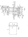
- the structure shown in Figure 6 has a particular advantage from the standpoint of adjustment and maintenance. It will be seen that the structure includes a plate 110 resting on a part 112 of the frame. of the equipment. The structure is located relative to the part 112 by a bearing housing 114 attached to the part 112 and containing a cylindrical portion 116 of the structure.
- the plate 110 can slide on the part 112 and rotate about the axis of shaft 95 so that the assembly shown in Figure 6 can be swung about this axis and into a position for more convenient adjustment and maintenance. This is also made possible by the fact that such movement takes place about the axis of the shaft 95 so that the engagement of the gears 92, 94 is not affected.
- the assembly shown in Figure 6 can be locked in position using a simple engagement fitting controlled by a handle 118 and with the structure locked in position by this handle it assumes the position shown in Figures 1 and 2. Such movement is particularly useful for adjusting the blade 76 ( Figure 4) of the stationary portion 72 of the cutter assembly 70.
- the spur gear 90 shown in Figure 6 is driven through a suitable drive chain from a main gear 121 shown at the bottom of Figure 7. It will become apparent that this ensures that the label carrier 36 shown in Figure 1 is driven synchronously with the notched roll 84. The reason for this will become evident from subsequent description.
- the label carrier 36 consists essentially of a large wheel 119 having a discontinuous periphery.
- Four raised peripheral pads 120, 122, 124 and 126 are provided spaced equally about the periphery of the wheel. As will be described with reference to Figure 7, these pads are provided with openings connected to a vacuum system to hold labels such as labels 44 and 46 on the pads.
- Figure 2 shows a label 129 which is projecting outside the label feeder assembly 40,• but has yet to be severed from the strip 22. It will be seen that the leading edge of the label projects beyond the leading end of the pad 126 whereas the label 44 which has been severed from the strip sits on the pad and does not overhang the pad. This is because the wheel is made to move with sufficient peripheral speed that it creates slippage between the pad 126 and the label 129. Because the vacuum system maintains the label in contact with the pad, a tension exists in the label and this ensures that the label is drawn into firm engagement with the pad. When the label is severed from the strip, it will have slipped on the wheel to a point where the leading end of the label lies immediately adjacent the leading end of the pad 126.
- a leading end is stripped off the wheel by a pair of belts 128 (one of which is seen in Figure 2 and both of which can be seen in Figure 7).
- belts 128 pass around the wheel 119 driven by a roll 130 which causes a linear velocity in the belts greater than the peripheral velocity of the wheel 119.
- Conventional bottle feeder 34 is driven also from the main gear 121 ( Figure 7) to cause bottles to be in position to receive labels from the wheel 110.
- the bottle 50 for instance (in Figure 2) has reached a reaction pad 132 supported by a wall 134 and is biased by the pad 132 into contact with the belts 128 so that the bottle is driven linearly along the conveyor 30 at half the speed of the belts 128.
- the belts guide the leading edge of the label into contact with the outer surface of the bottle 50, which is moving faster than the label, so that as soon as the adhesive on the label comes into contact with the bottle, the label is pulled faster than the wheel 119 while maintaining sliding engagement with the associated one of the raised pads on the wheel.
- This tension ensures an even and controlled application of the label as the bottle rolls in contact with the pad 132.
- an auxiliary vacuum pad 136 is provided to further support the label after it has slid off the raised pad on the wheel 119, and before it is applied completely to the bottle 50. This will be better understood with reference to Figure 3 which shows a sectional view through the auxiliary vacuum pad 136 lying between the two belts 128.
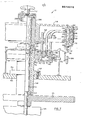
- the wheel 119 includes two groups of vacuum pipes, an outer group 140 and an inner group 142. It will be seen that the inner pipes 142 serve the centres of the labels. With this arrangement it is possible to release or more positively secure the centre of the label independently of the ends and vice versa.
- the carrier rotates about an axis defined by a vertical shaft 144 driven from a main drive and gear box 146.
- the main gear 121 is attached to the shaft 144 and drives all of the other parts of the equipment through a conventional drive chain.
- the shaft 144 passes through a bearing housing 148 and is supported at ends of the housing by suitable bearings 150, 152 which include a thrust bearing.
- the bearing housing 148 includes a flange 154 sitting on a part 156 of the frame of the equipment and attached by suitable bolts 158.
- the bearing housing 148 also supports a vacuum distributor 160 having a lower part 162 fixed to the bearing housing by a further flange 164 and an upper or movable portion 166 which rotates with the wheel 119 driven by a pin 168 as will be described.
- the portions 162 and 166 are machined to define smooth faces in engagement with one another to facilitate the upper portion riding on the lower portion as the upper portion rotates.
- the lower portion 162 defines an annular recess 170 covered by a plate 172 and seal 174. These parts combine to define an annular manifold served by a vacuum connection 176.
- This manifold then serves the pipes 140, 142 by way of concentric rows of openings 178, 180 in the fixed part 162 and corresponding openings 182, 184 associated with the pipes 140, 142.
- the openings 178, 180 extend partially about the part 162 as illustrated in broken outline in Figure 2. Consequently, as the wheel 119 rotates, the openings 182, 184 are affected by vacuum when they coincide with openings 178, 180. It will be evident that the size of openings 178, 180 can be varied to provide different degrees of vacuum in the pipes 140, 142 as the wheel 119 rotates.
- Each of the pipes 140, 142 terminates at its upper extremity in a fitting which connects the pipe to one of a series of upright bores 186 ( Figure 7).
- Each of these bores acts as a manifold to a series of radial openings 188 for drawing air from the front of one of the raised pads such as pad 120.
- a label is shown in ghost outline fixed to such a pad.
- these pads are preferably of an elastomeric material bonded to an outer ring 190 which is made up of two halves and attached to the main body of the wheel.
- Each of the bores 186 associated with the pipes 140 at the leading end of a label has a vacuum sensor 192 at its lower end. This sensor normally rides on a track 194 until it passes a point at which a label should be picked up. In the event that a label is picked up there will be a build up of negative pressure in the bore 186 which will retain a loose plunger 196 against a seat 198 to thereby seal the bore 186. The plunger 196 will then be in a raised position and as the wheel 119 rotates the plunger will pass above an electrical switch 200.
- the plunger 196 After the plunger 196 has met the switch 200, it will continue in the dropped or lower porition until it reaches an incline 204 at a leading end of the track 194 which raises the plunger back to a position in which it engages seat 198.
- the wheel 119 includes a central boss 206 which locates on an upper extremity of the shaft 144 and is engaged on the shaft by a key 208.
- An extension 209 on the upper extremity of the shaft is threaded to receive a knob 212 which retains the wheel on the shaft. It will be evident that once the knob is removed it is possible to disconnnect the pipes 140, 142 and to lift the wheel off the equipment. Once this is done the distributor can be removed so that it is quite simple to service the equipment and to change parts if this is necessary for different labels.
- the holes 178 terminate at a position corresponding to the circumferential position of the conduit 140 just after the leading edge of the label is detached from the suction pad.
- the initial contact between the label and the bottle takes place just where the belt leaves the wheel and the differential speed between the belt and the wheel ensures tension in the label. This differential speed is achieved using a particular arrangement of belt engagement on the wheel 119 as will be described.
- the belts 128 are driven continuously by roll 130 (Figure 2) which in turn is driven from the main gear 121 ( Figure 7) through suitable drive members. Tension is maintained in the belts 128 by an idler 222 and, as mentioned earlier, the single belt 138 is also driven by the roll 130.
- This belt 138 passes around an idler 224 and tensioning idler 226 so that the belts 128 and 138 combine to roll the bottles along the reaction pad 132 and a subsequent pad 228 with a linear velocity substantially equal to that of the conveyor 30.
- Guides . 230 are shown in ghost outline to support the bottles at the neck and to limit the possibility of the bottles being toppled by engagement with the labelling equipment.
- each of the belts 128 in fact performs several functions: it engages the surface of the bottle 50 at the delivery point, and starts the rolling motion of the bottle between the belts and the pad 132 (as shown in Figure 1); it progressively strips the label 48 from the pad 124; it progressively applies the label 48 to the surface of the bottle; once application of the label has started, it continues to impart rolling motion to the bottle, with the label 48 now interposed between the belts 128 and the bottle 50 (as shown in Figure 2).
- each of the belts 128 can be regarded as label applicator means extending between the carrier 36, and the surface of the bottle, and also as part of drive means in a drive system to roll the bottle and in so doing to move the surface of the bottle from the delivery position at a speed greater than the peripheral speed of the carrier.
Landscapes
- Engineering & Computer Science (AREA)
- Mechanical Engineering (AREA)
- Life Sciences & Earth Sciences (AREA)
- Forests & Forestry (AREA)
- Labeling Devices (AREA)
- Details Of Cutting Devices (AREA)
- Making Paper Articles (AREA)
Applications Claiming Priority (4)
| Application Number | Priority Date | Filing Date | Title |
|---|---|---|---|
| CA000317428A CA1155806A (en) | 1978-12-05 | 1978-12-05 | Labelling equipment |
| CA317428 | 1978-12-05 | ||
| CA340,448A CA1126219A (en) | 1979-11-22 | 1979-11-22 | Labelling equipment |
| CA340448 | 1979-11-22 |
Related Parent Applications (2)
| Application Number | Title | Priority Date | Filing Date |
|---|---|---|---|
| EP19790302772 Division EP0018457B1 (de) | 1978-12-05 | 1979-12-04 | Etikettieranlage |
| EP79302772.3 Division | 1979-12-04 |
Publications (2)
| Publication Number | Publication Date |
|---|---|
| EP0078076A2 true EP0078076A2 (de) | 1983-05-04 |
| EP0078076A3 EP0078076A3 (de) | 1985-03-20 |
Family
ID=25668837
Family Applications (2)
| Application Number | Title | Priority Date | Filing Date |
|---|---|---|---|
| EP19790302772 Expired EP0018457B1 (de) | 1978-12-05 | 1979-12-04 | Etikettieranlage |
| EP19820201280 Withdrawn EP0078076A3 (de) | 1978-12-05 | 1979-12-04 | Schneider für Bänder |
Family Applications Before (1)
| Application Number | Title | Priority Date | Filing Date |
|---|---|---|---|
| EP19790302772 Expired EP0018457B1 (de) | 1978-12-05 | 1979-12-04 | Etikettieranlage |
Country Status (3)
| Country | Link |
|---|---|
| US (2) | US4526645A (de) |
| EP (2) | EP0018457B1 (de) |
| DE (1) | DE2966995D1 (de) |
Cited By (8)
| Publication number | Priority date | Publication date | Assignee | Title |
|---|---|---|---|---|
| EP0241709A1 (de) * | 1986-03-18 | 1987-10-21 | John Waddington PLC | Aufbringen von Etiketten auf Gegenständen |
| EP0352384A1 (de) * | 1987-05-28 | 1990-01-31 | Owens-Illinois Plastic Products Inc. | Verfahren und Vorrichtung zum Anbringen von Etiketten auf blasgeformten Artikeln |
| EP0444547A1 (de) * | 1990-02-26 | 1991-09-04 | Focke & Co. (GmbH & Co.) | Verfahren und Vorrichtung zum Fördern von Banderolen zwecks Übergabe an Packungen |
| EP0704378A1 (de) * | 1994-09-30 | 1996-04-03 | Intersleeve B.V. | Vorrichtung zum Anbringen eines Etiketts auf einer Flasche oder dergl. |
| EP0749906A3 (de) * | 1995-06-09 | 1997-03-19 | Tamarack Products Inc | Verfahren und Vorrichtung zum Schneiden dünner Bänder und Folien |
| WO2011012333A1 (en) * | 2009-07-29 | 2011-02-03 | Sidel S.P.A. | Cutting unit for labelling machines |
| WO2012107583A1 (en) * | 2011-02-11 | 2012-08-16 | Sidel S.P.A. Con Socio Unico | Stationary blade assembly |
| EP2711303A1 (de) * | 2012-09-19 | 2014-03-26 | Krones AG | Etikettieraggregat zum Etikettieren von Behältnissen mit Etiketten |
Families Citing this family (43)
| Publication number | Priority date | Publication date | Assignee | Title |
|---|---|---|---|---|
| IT1139281B (it) * | 1980-10-24 | 1986-09-24 | Sun Chemical Corp | Macchina etichettatrice |
| DK360783A (da) * | 1982-08-09 | 1984-02-10 | Willett Int Ltd | Etiketteringsapparat, og fremgangsmaade til etikettering |
| US4832776A (en) * | 1982-11-12 | 1989-05-23 | Formost Packaging Machines, Inc. | Process for applying a patch |
| GB2130173B (en) * | 1982-11-12 | 1987-05-28 | Formost Packaging Machines Inc | Bag mouth closure and method and apparatus for making the same |
| US4724036A (en) * | 1986-02-21 | 1988-02-09 | Owens-Illinois Plastic Products Inc. | Progressively ported vacuum drum for labeling machines |
| US4842660A (en) * | 1986-03-28 | 1989-06-27 | New Jersey Machine, Inc. | Continuous motion pressure sensitive labeling system and method |
| US4687535A (en) * | 1986-03-28 | 1987-08-18 | New Jersey Machine, Inc. | Vacuum drum labeling system |
| US4671843A (en) * | 1986-04-28 | 1987-06-09 | Owens-Illinois, Inc. | Label transport vacuum drum |
| GB2208840B (en) * | 1987-08-13 | 1991-12-11 | New Jersey Machine Inc | Labelling system |
| US4931122A (en) * | 1988-05-31 | 1990-06-05 | B & H Manufacturing Company, Inc. | Straight through labelling machine |
| IT1253216B (it) * | 1991-10-21 | 1995-07-11 | Gd Spa | Dispositivo per l'applicazione di fascette adesive a pacchetti |
| US5401353A (en) * | 1992-06-30 | 1995-03-28 | Cms Gilbreth Packaging Systems | Apparatus and method for applying labels onto small cylindrical articles using static wipers |
| US5344519A (en) * | 1992-06-30 | 1994-09-06 | Cms Gilbreth Packaging Systems | Apparatus for applying labels onto small cylindrical articles having improved vacuum and air pressure porting for label transport drum |
| US5350482A (en) * | 1992-06-30 | 1994-09-27 | Cms Gilbreth Packaging Systems | Apparatus and method for applying labels onto small cylindrical articles |
| US5399216A (en) * | 1992-06-30 | 1995-03-21 | Cms Gilbreth Packaging Systems | Apparatus and method for applying labels onto small cylindrical articles using pressure applicator to prevent label mismatching |
| US5405487A (en) * | 1992-06-30 | 1995-04-11 | Cms Gilbreth Packaging Systems, Inc. | Apparatus and method for applying labels onto small cylindrical articles and web and adhesive delivery mechanism |
| GB2317156B (en) * | 1994-01-26 | 1998-07-08 | Molins Plc | Apparatus for severing labels from a web of label material |
| US5458728A (en) * | 1994-06-27 | 1995-10-17 | Galchefski; John | Apparatus and method for applying labels onto small cylindrical articles with improved seam formation by retarded article rotation |
| WO1996009213A2 (en) * | 1994-09-19 | 1996-03-28 | Cms Gilbreth Packaging Systems, Inc. | Labelling machine |
| US5538575A (en) * | 1994-10-21 | 1996-07-23 | Cms Gilbreth Packaging Systems | Labelling machine and method for applying adhesive to labels for attachment to containers and article therefore |
| US5749990A (en) * | 1994-11-21 | 1998-05-12 | Cms Gillbreth Packaging Systems, Inc. | Method and apparatus for applying labels to articles using bottom feed conveying unit |
| US5779835A (en) * | 1994-11-21 | 1998-07-14 | Cms Gilbreth Packaging Systems, Inc. | Method and apparatus for applying labels to articles using bottom feed chain conveyor |
| US5480502A (en) * | 1994-11-21 | 1996-01-02 | Cms Gilbreth Packaging Systems, Inc. | Method and apparatus for applying labels to articles using cooling air on label receiving positions |
| DE29504553U1 (de) * | 1995-03-17 | 1995-06-14 | Voith Sulzer Papiermaschinen GmbH, 89522 Heidenheim | Vorrichtung zum Stabilisieren einer Warenbahn |
| US5486253A (en) * | 1995-05-17 | 1996-01-23 | B&H Manufacturing Company | Method of labeling containers |
| US5863382A (en) * | 1995-09-22 | 1999-01-26 | Trine Manufacturing Company, Inc. | Labeling machine with improved cutter assembly |
| US6003580A (en) * | 1995-09-29 | 1999-12-21 | Stabon International, Inc. | Placement apparatus for thin flexible members |
| US6450230B1 (en) | 1999-06-24 | 2002-09-17 | S-Con, Inc. | Labeling apparatus and methods thereof |
| US6328832B1 (en) | 1998-06-26 | 2001-12-11 | S-Con, Inc. | Labeling apparatus with web registration, web cutting and carrier mechanisms, and methods thereof |
| US6220330B1 (en) * | 1998-10-01 | 2001-04-24 | Dorner Mfg. Corp. | Conveyor system incorporating article guide and positioning arrangement for a labeling station |
| CA2253018A1 (en) | 1998-11-05 | 2000-05-05 | Associpak International Inc. | Labeling machine |
| US6347657B1 (en) | 1999-09-08 | 2002-02-19 | B & H Manufacturing Company, Inc. | Lightweight vacuum drum |
| US7147028B2 (en) * | 2003-05-13 | 2006-12-12 | Sensormatic Electronics Corporation | Label application system |
| GB0501369D0 (en) * | 2005-01-22 | 2005-03-02 | Stepping Stones Invest Ltd | Improvements to labels and application apparatus therefor |
| US10040591B2 (en) | 2012-08-01 | 2018-08-07 | Label-Aire, Inc. | High speed label applicator and methods |
| JP2014234169A (ja) * | 2013-05-31 | 2014-12-15 | サトーホールディングス株式会社 | ラベル貼付装置 |
| WO2016118121A1 (en) * | 2015-01-20 | 2016-07-28 | Label-Aire, Inc. | High speed label applicator and methods |
| CN104875934A (zh) * | 2015-03-31 | 2015-09-02 | 上海宿田自动化设备有限公司 | 一种新型贴标机 |
| CN106419324A (zh) * | 2016-08-24 | 2017-02-22 | 苏州卫捷医药科技有限公司 | 一种医用贴签旋转储存单元 |
| US11254461B1 (en) | 2017-02-14 | 2022-02-22 | Label-Aire, Inc. | High speed label applicator systems and methods |
| US10822134B1 (en) | 2017-02-14 | 2020-11-03 | Label-Aire, Inc. | High speed label applicator systems and methods |
| CN108638170B (zh) * | 2018-05-03 | 2020-03-06 | 上海沁全精密机械有限公司 | 一种饮料瓶全自动分段方法 |
| US11731797B2 (en) | 2019-05-21 | 2023-08-22 | Inline Plastics Corp. | Side wrap labeling apparatus |
Family Cites Families (20)
| Publication number | Priority date | Publication date | Assignee | Title |
|---|---|---|---|---|
| GB420763A (en) * | 1932-07-21 | 1934-12-07 | British Thomson Houston Co Ltd | Improvements in and relating to control systems for machines operating upon lengths of material such as paper |
| US2372020A (en) * | 1942-02-17 | 1945-03-20 | Lynch Mfg Corp | Wrapping paper cutting mechanism |
| GB668082A (en) * | 1948-12-15 | 1952-03-12 | Leslie Gordon Forster | Improvements in or relating to means for cutting thin material |
| US2645373A (en) * | 1950-02-17 | 1953-07-14 | Rose Brothers Ltd | Feeding of labels, sheets, and the like from a stack |
| GB837739A (en) * | 1957-06-07 | 1960-06-15 | Winkler Richard | Improvements in or relating to the production of window envelopes and the like articles from a continuous band of material |
| US3159521A (en) * | 1960-12-12 | 1964-12-01 | Strunck & Co H | Apparatus to sever, print and apply labels to containers |
| GB1011722A (en) * | 1961-06-14 | 1965-12-01 | Molins Organisation Ltd | Improvements in or relating to the feeding of webs of material |
| US3577293A (en) * | 1962-09-19 | 1971-05-04 | Continental Can Co | Method of labelling cylindrical objects |
| US3555764A (en) * | 1967-02-01 | 1971-01-19 | Continental Can Co | Apparatus and method for securing closures to container bodies |
| US3676271A (en) * | 1967-10-23 | 1972-07-11 | American Can Co | Apparatus for applying a strip member to a cylindrical container body |
| DE1760342A1 (de) * | 1968-05-06 | 1971-08-12 | Klebetechnik Gmbh | Vorrichtung zum selbsttaetigen Umwickeln abwaelzbarer Koerper |
| US3834963A (en) * | 1970-01-23 | 1974-09-10 | B & J Mfg Co | Method for applying labels to containers |
| US3765991A (en) * | 1970-01-23 | 1973-10-16 | B & J Mfg Co | Labeling apparatus |
| US3733949A (en) * | 1971-06-21 | 1973-05-22 | Paper Converting Machine Co | Noise reduction strip for shear cut perforator |
| US3957570A (en) * | 1971-10-13 | 1976-05-18 | F. L. Smithe Machine Company, Inc. | Machinery for patching envelopes and the like |
| US4108710A (en) * | 1972-02-14 | 1978-08-22 | B & H Manufacturing Company, Inc. | Apparatus for applying labels to containers |
| FR2218743A6 (de) * | 1973-02-19 | 1974-09-13 | Herve Fils Papet Sentier | |
| US3900859A (en) * | 1974-01-15 | 1975-08-19 | O M I Corp Of America | Apparatus and method for optical annotation of orthophotographs |
| US3938698A (en) * | 1974-11-27 | 1976-02-17 | Avery Products Corporation | Apparatus for dispensing adhesive labels |
| US4332635A (en) * | 1980-07-03 | 1982-06-01 | American Can Company | Cup labeling method and apparatus |
-
1979
- 1979-12-04 EP EP19790302772 patent/EP0018457B1/de not_active Expired
- 1979-12-04 DE DE7979302772T patent/DE2966995D1/de not_active Expired
- 1979-12-04 EP EP19820201280 patent/EP0078076A3/de not_active Withdrawn
-
1981
- 1981-10-29 US US06/316,266 patent/US4526645A/en not_active Expired - Lifetime
- 1981-11-13 US US06/321,004 patent/US4448629A/en not_active Expired - Fee Related
Cited By (17)
| Publication number | Priority date | Publication date | Assignee | Title |
|---|---|---|---|---|
| EP0241709A1 (de) * | 1986-03-18 | 1987-10-21 | John Waddington PLC | Aufbringen von Etiketten auf Gegenständen |
| EP0352384A1 (de) * | 1987-05-28 | 1990-01-31 | Owens-Illinois Plastic Products Inc. | Verfahren und Vorrichtung zum Anbringen von Etiketten auf blasgeformten Artikeln |
| EP0444547A1 (de) * | 1990-02-26 | 1991-09-04 | Focke & Co. (GmbH & Co.) | Verfahren und Vorrichtung zum Fördern von Banderolen zwecks Übergabe an Packungen |
| US5203953A (en) * | 1990-02-26 | 1993-04-20 | Focke & Co. | Process and apparatus for conveying labels to be transferred to a (cigarette) pack |
| EP0704378A1 (de) * | 1994-09-30 | 1996-04-03 | Intersleeve B.V. | Vorrichtung zum Anbringen eines Etiketts auf einer Flasche oder dergl. |
| US5653849A (en) * | 1994-09-30 | 1997-08-05 | Intersleeve B.V. | Device for applying a label to a bottle or a similar object |
| EP0749906A3 (de) * | 1995-06-09 | 1997-03-19 | Tamarack Products Inc | Verfahren und Vorrichtung zum Schneiden dünner Bänder und Folien |
| AU704794B2 (en) * | 1995-06-09 | 1999-05-06 | Tamarack Products, Inc. | Method and apparatus for cutting thin tapes and films |
| WO2011012333A1 (en) * | 2009-07-29 | 2011-02-03 | Sidel S.P.A. | Cutting unit for labelling machines |
| WO2011012926A1 (en) * | 2009-07-29 | 2011-02-03 | Sidel S.P.A. | Cutting unit for labelling machines |
| CN102574601A (zh) * | 2009-07-29 | 2012-07-11 | 西得乐公开有限公司 | 用于贴标签机的切割单元 |
| CN102574601B (zh) * | 2009-07-29 | 2014-08-27 | 西得乐公开有限公司 | 用于贴标签机的切割单元及其固定叶片组件 |
| WO2012107583A1 (en) * | 2011-02-11 | 2012-08-16 | Sidel S.P.A. Con Socio Unico | Stationary blade assembly |
| CN103442987A (zh) * | 2011-02-11 | 2013-12-11 | 西得乐独资股份公司 | 固定刀片组件 |
| CN103442987B (zh) * | 2011-02-11 | 2015-02-25 | 西得乐独资股份公司 | 固定刀片组件 |
| US9289911B2 (en) | 2011-02-11 | 2016-03-22 | Sidel S.P.A. Con Socio Unico | Stationary blade assembly |
| EP2711303A1 (de) * | 2012-09-19 | 2014-03-26 | Krones AG | Etikettieraggregat zum Etikettieren von Behältnissen mit Etiketten |
Also Published As
| Publication number | Publication date |
|---|---|
| US4526645A (en) | 1985-07-02 |
| DE2966995D1 (en) | 1984-06-20 |
| EP0018457B1 (de) | 1984-05-16 |
| US4448629A (en) | 1984-05-15 |
| EP0078076A3 (de) | 1985-03-20 |
| EP0018457A1 (de) | 1980-11-12 |
Similar Documents
| Publication | Publication Date | Title |
|---|---|---|
| US4448629A (en) | Cutter assembly | |
| US4323416A (en) | Labelling equipment | |
| US4561928A (en) | Labelling machine | |
| US4447280A (en) | Labelling machine | |
| EP0944528B1 (de) | Etikettiervorrichtung mit etikettenrolle | |
| US4108710A (en) | Apparatus for applying labels to containers | |
| EP0827483B1 (de) | Umwickler mit befestiger für das wickelende | |
| US3765991A (en) | Labeling apparatus | |
| US5950510A (en) | Decelerating mechanism for printed products | |
| CN101605697A (zh) | 拉伸薄膜套管式标签敷抹装置 | |
| US5607526A (en) | Label-applying method and apparatus | |
| US5297751A (en) | Method of replacing strip material on a manufacturing machine | |
| US5129294A (en) | Method of replacing and adjusting preprinted strip material on a manufacturing machine | |
| US4045275A (en) | Machine for applying tapes to moving product | |
| CA1126219A (en) | Labelling equipment | |
| EP0095890B1 (de) | Vorrichtung zur Herstellung von durchsichtigen Aufklebern | |
| EP0787652B1 (de) | Vorrichtung zum Zuführen von Zuschnitten in einer Zigarettenverpackungsmaschine | |
| CA1177792A (en) | Labelling machine | |
| US4331498A (en) | Method of and apparatus for wrapping tops of bottles with foil | |
| CA2029541A1 (en) | Neck labelling machine | |
| US3707424A (en) | Adjustable label form slitter for addressing machines | |
| JPH0648429A (ja) | 帯状材料を送るための方法および装置 | |
| EP0664225A1 (de) | Verfahren und Vorrichtung zur Herstellung eines Notizblocks | |
| EP0545265B1 (de) | Verfahren und Vorrichtung zum Zuführen von Verpackungsmaterial an einer Verpackungsmaschine | |
| JPH0890487A (ja) | 引裂き条片の製作方法とその装置 |
Legal Events
| Date | Code | Title | Description |
|---|---|---|---|
| PUAI | Public reference made under article 153(3) epc to a published international application that has entered the european phase |
Free format text: ORIGINAL CODE: 0009012 |
|
| AC | Divisional application: reference to earlier application |
Ref document number: 18457 Country of ref document: EP |
|
| AK | Designated contracting states |
Designated state(s): DE FR GB IT NL |
|
| PUAL | Search report despatched |
Free format text: ORIGINAL CODE: 0009013 |
|
| AK | Designated contracting states |
Designated state(s): DE FR GB IT NL |
|
| STAA | Information on the status of an ep patent application or granted ep patent |
Free format text: STATUS: THE APPLICATION HAS BEEN WITHDRAWN |
|
| 18W | Application withdrawn |
Withdrawal date: 19850607 |
|
| RIN1 | Information on inventor provided before grant (corrected) |
Inventor name: GROEGER, HEINZ K. Inventor name: MALTHOUSE, MARTIN D. |