EP0077722A1 - Sonde thermique et application de celle-ci à une installation de chauffage, notamment par infra-rouge - Google Patents
Sonde thermique et application de celle-ci à une installation de chauffage, notamment par infra-rouge Download PDFInfo
- Publication number
- EP0077722A1 EP0077722A1 EP82401874A EP82401874A EP0077722A1 EP 0077722 A1 EP0077722 A1 EP 0077722A1 EP 82401874 A EP82401874 A EP 82401874A EP 82401874 A EP82401874 A EP 82401874A EP 0077722 A1 EP0077722 A1 EP 0077722A1
- Authority
- EP
- European Patent Office
- Prior art keywords
- transducer
- probe
- probe according
- support member
- support
- Prior art date
- Legal status (The legal status is an assumption and is not a legal conclusion. Google has not performed a legal analysis and makes no representation as to the accuracy of the status listed.)
- Ceased
Links
Images
Classifications
-
- G—PHYSICS
- G01—MEASURING; TESTING
- G01J—MEASUREMENT OF INTENSITY, VELOCITY, SPECTRAL CONTENT, POLARISATION, PHASE OR PULSE CHARACTERISTICS OF INFRARED, VISIBLE OR ULTRAVIOLET LIGHT; COLORIMETRY; RADIATION PYROMETRY
- G01J5/00—Radiation pyrometry, e.g. infrared or optical thermometry
- G01J5/70—Passive compensation of pyrometer measurements, e.g. using ambient temperature sensing or sensing of temperature within housing
-
- G—PHYSICS
- G01—MEASURING; TESTING
- G01J—MEASUREMENT OF INTENSITY, VELOCITY, SPECTRAL CONTENT, POLARISATION, PHASE OR PULSE CHARACTERISTICS OF INFRARED, VISIBLE OR ULTRAVIOLET LIGHT; COLORIMETRY; RADIATION PYROMETRY
- G01J5/00—Radiation pyrometry, e.g. infrared or optical thermometry
- G01J5/0022—Radiation pyrometry, e.g. infrared or optical thermometry for sensing the radiation of moving bodies
-
- G—PHYSICS
- G01—MEASURING; TESTING
- G01J—MEASUREMENT OF INTENSITY, VELOCITY, SPECTRAL CONTENT, POLARISATION, PHASE OR PULSE CHARACTERISTICS OF INFRARED, VISIBLE OR ULTRAVIOLET LIGHT; COLORIMETRY; RADIATION PYROMETRY
- G01J5/00—Radiation pyrometry, e.g. infrared or optical thermometry
- G01J5/02—Constructional details
- G01J5/04—Casings
-
- G—PHYSICS
- G01—MEASURING; TESTING
- G01J—MEASUREMENT OF INTENSITY, VELOCITY, SPECTRAL CONTENT, POLARISATION, PHASE OR PULSE CHARACTERISTICS OF INFRARED, VISIBLE OR ULTRAVIOLET LIGHT; COLORIMETRY; RADIATION PYROMETRY
- G01J5/00—Radiation pyrometry, e.g. infrared or optical thermometry
- G01J5/02—Constructional details
- G01J5/08—Optical arrangements
- G01J5/0853—Optical arrangements having infrared absorbers other than the usual absorber layers deposited on infrared detectors like bolometers, wherein the heat propagation between the absorber and the detecting element occurs within a solid
-
- G—PHYSICS
- G01—MEASURING; TESTING
- G01J—MEASUREMENT OF INTENSITY, VELOCITY, SPECTRAL CONTENT, POLARISATION, PHASE OR PULSE CHARACTERISTICS OF INFRARED, VISIBLE OR ULTRAVIOLET LIGHT; COLORIMETRY; RADIATION PYROMETRY
- G01J5/00—Radiation pyrometry, e.g. infrared or optical thermometry
- G01J5/02—Constructional details
- G01J5/08—Optical arrangements
- G01J5/0887—Integrating cavities mimicking black bodies, wherein the heat propagation between the black body and the measuring element does not occur within a solid; Use of bodies placed inside the fluid stream for measurement of the temperature of gases; Use of the reemission from a surface, e.g. reflective surface; Emissivity enhancement by multiple reflections
-
- G—PHYSICS
- G01—MEASURING; TESTING
- G01J—MEASUREMENT OF INTENSITY, VELOCITY, SPECTRAL CONTENT, POLARISATION, PHASE OR PULSE CHARACTERISTICS OF INFRARED, VISIBLE OR ULTRAVIOLET LIGHT; COLORIMETRY; RADIATION PYROMETRY
- G01J5/00—Radiation pyrometry, e.g. infrared or optical thermometry
- G01J5/02—Constructional details
- G01J5/08—Optical arrangements
- G01J5/0893—Arrangements to attach devices to a pyrometer, i.e. attaching an optical interface; Spatial relative arrangement of optical elements, e.g. folded beam path
-
- G—PHYSICS
- G01—MEASURING; TESTING
- G01K—MEASURING TEMPERATURE; MEASURING QUANTITY OF HEAT; THERMALLY-SENSITIVE ELEMENTS NOT OTHERWISE PROVIDED FOR
- G01K1/00—Details of thermometers not specially adapted for particular types of thermometer
- G01K1/16—Special arrangements for conducting heat from the object to the sensitive element
-
- G—PHYSICS
- G01—MEASURING; TESTING
- G01J—MEASUREMENT OF INTENSITY, VELOCITY, SPECTRAL CONTENT, POLARISATION, PHASE OR PULSE CHARACTERISTICS OF INFRARED, VISIBLE OR ULTRAVIOLET LIGHT; COLORIMETRY; RADIATION PYROMETRY
- G01J5/00—Radiation pyrometry, e.g. infrared or optical thermometry
- G01J5/0022—Radiation pyrometry, e.g. infrared or optical thermometry for sensing the radiation of moving bodies
- G01J5/0025—Living bodies
-
- G—PHYSICS
- G01—MEASURING; TESTING
- G01J—MEASUREMENT OF INTENSITY, VELOCITY, SPECTRAL CONTENT, POLARISATION, PHASE OR PULSE CHARACTERISTICS OF INFRARED, VISIBLE OR ULTRAVIOLET LIGHT; COLORIMETRY; RADIATION PYROMETRY
- G01J5/00—Radiation pyrometry, e.g. infrared or optical thermometry
- G01J5/02—Constructional details
- G01J5/04—Casings
- G01J5/048—Protective parts
Definitions
- the invention relates to a thermal probe, more particularly a probe making it possible to capture the "resulting" temperature of a heated room, and its application to a heating installation.
- thermal probes are already known. In general, these probes are capable of giving information corresponding to the surrounding temperature. However, they cannot give information corresponding to the real value as it is perceived by the user. Indeed, when a room is heated to a temperature t, when a certain infrared radiation enters the heated room, current probes cannot give information on the energy of such infrared radiation, actually absorbed by the user.
- thermometers or probes useful for taking the temperature of patients.
- a probe is constituted by a thermistor placed in a bimetallic enclosure, namely a housing whose thin wall is metallic and is reinforced by a layer of a metal having a very high mechanical resistance.
- the inner metal has a higher thermal conductivity, so heat is transmitted by conduction very quickly through the metal to the thermistor.
- These probes therefore use the principle of heat transmission by conduction. They are used to take the temperature of a living body in contact with the probe. However, they do not make it possible to capture the temperature remotely or to capture the "resulting" temperature, namely the sum of the thermal energy transmitted by convection by the air or the ambient atmosphere and by the existing infrared radiation. at the point where the measurement is made.
- the present invention aims to remedy these drawbacks, and for this purpose it proposes a probe making it possible to capture the ambient "resulting" temperature, the probe comprising a rigid support member, good conductor of heat and a transducer rigidly associated or not with the support. and in thermal contact or not with it, an electric cable being electrically associated with the transducer.
- the support member has externally qualities as close as possible to the black body, for example, it is painted black.
- the transducer is placed on the face internal of the support member, opposite to that having the characteristics of the black body. It can also be located inside of the probe without being in contact with the support member. More particularly, the support member is metallic, therefore a good conductor of heat, and is for example in the form of a pseudo-cylindrical tube, in particular made of aluminum.
- the thermal probe according to the invention therefore makes it possible to identify the ambient temperature and possibly the energy of the infrared radiation, which is emitted by the heating device. Because the infrared radiation is absorbed by the support member having qualities close to those of the black body, the infrared waves striking the black body are then absorbed by it and transformed into heat energy then transmitted through the metal wall of the support member which is a good conductor of heat.
- the temperature identified by the transducer is therefore substantially the "resulting" temperature, that is to say the sum of the thermal energy corresponding to the temperature prevailing in the atmosphere in which the probe is immersed and the energy of the infrared radiation hitting this probe.
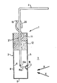
- the single figure is a schematic view of a thermal probe according to the invention.
- the thermal probe 1 shown in the diagram comprises a rigid support member 2, a transducer 3 rigidly associated with the support member 2 and in thermal contact with it.
- the transducer 3 is a transducer making it possible to transform the temperature into an electrical signal. More particularly, this electrical signal is a current or a voltage.
- a transducer is used which is undisturbed and insensitive to parasites. external and independent of the cable length. It allows a faithful representation of the temperature.
- the thermal probe 1 also comprises a shielded electrical cable 4 electrically associated with the transducer 3.
- the support member 2 has externally qualities as close as possible to the black body in order to absorb the possible infrared radiation as best as possible.
- this support member may have an external face 5 painted black.
- the transducer 3 is placed on the internal face 6 of the support member 2, opposite to that having the characteristics of the black body. However, in another embodiment not shown, it can be located inside the probe without being in contact with the support member 2. It can also not be rigidly associated with the support 2.
- the support member 2 is in the form of a tube, a good conductor of heat, for example metallic, in particular aluminum.
- the infrared rays X emitted outside 7 of the tube are completely absorbed by the external face 5 of the wall 8 which is painted black and these radiations are transmitted through this wall 8, to the internal face 6 thereof, the fact that the material of the support 2 is a good heat conductive material, for example metallic.
- the transducer 3 being placed on the internal face 6 of the tube 2, it captures the sum of the ambient thermal energy and of the energy emitted by the infrared radiation and captured by the tube and it transforms this value into electrical variables. More particularly, it transforms the "resulting" temperature value into a current intensity variable.
- the tube 2 is more particularly a pseudo-cylindrical tube with a circular cross section. It is closed at its lower end 9, preferably by a metal patch which is welded or glued.
- the transducer 3 is fixed on the lateral face of the support member 2, in a position away from the end 9. It can be fixed inside the tube, on the part 9 closing the end of the tube.
- the transducer 3 is fixed to the internal face 6 of the tube 2 by a thermally conductive resin forming the seal 18.
- the end 10 of the tube 2 opposite the end 9 is closed by a plug 12, for example made of expanded polystyrene.
- the purpose of this plug 12 is to hold the cable 4 coaxially with the pseudo-cylindrical tube 2.
- the thermal probe further comprises a hooking member enabling it to be fixed to a support.
- This hooking member 19 is particularly an S-hook whose curved end 20 is situated outside the support member 2 and whose opposite end 21 which is also curved, is embedded in a resin 11.
- This resin 11 is poured directly onto the plug 12, this plug 12 having the function of avoiding losses of resin during its pouring. The resin 11 therefore maintains the hook 19 and the cable 4 in position.
- the cable 4 is a shielded cable whose central conductor 15a is connected to the conductor 3 and whose helical conductor 15b is also connected to the transducer 3.
- the cable 4 can be connected to the probe body 2 by a withdrawable connection device located in particular at the end of the cable 4 which is located in the probe body 2.
- the transducer 3 is therefore perfectly isolated inside the support member 2 which forms a sealed tube.
- the transducer 3 is placed in the sealed part formed by the side wall 8 of the tube, the closed end 9 of the tube and the plug 12.
- the probe according to the invention therefore makes it possible to capture the ambient temperature prevailing outside 7 of the probe as well as the infrared X-rays arriving on this probe.
- the probe is used in particular to measure the heat perceived by animals or living organisms placed in an enclosure heated by infrared radiation. When the infrared radiation hits the probe, the probe captures the values of the ambient temperature and the energy of the infrared radiation. When infrared radiation is not emitted, the probe only captures the ambient temperature values.
Landscapes
- Physics & Mathematics (AREA)
- General Physics & Mathematics (AREA)
- Spectroscopy & Molecular Physics (AREA)
- Measuring And Recording Apparatus For Diagnosis (AREA)
- Radiation Pyrometers (AREA)
- Measuring Temperature Or Quantity Of Heat (AREA)
Applications Claiming Priority (2)
| Application Number | Priority Date | Filing Date | Title |
|---|---|---|---|
| FR8119301A FR2514499A1 (fr) | 1981-10-14 | 1981-10-14 | Sonde thermique et application de celle-ci a une installation de chauffage, notamment par infra-rouge |
| FR8119301 | 1981-10-14 |
Publications (1)
| Publication Number | Publication Date |
|---|---|
| EP0077722A1 true EP0077722A1 (fr) | 1983-04-27 |
Family
ID=9263023
Family Applications (1)
| Application Number | Title | Priority Date | Filing Date |
|---|---|---|---|
| EP82401874A Ceased EP0077722A1 (fr) | 1981-10-14 | 1982-10-12 | Sonde thermique et application de celle-ci à une installation de chauffage, notamment par infra-rouge |
Country Status (3)
| Country | Link |
|---|---|
| US (1) | US4531844A (cg-RX-API-DMAC7.html) |
| EP (1) | EP0077722A1 (cg-RX-API-DMAC7.html) |
| FR (1) | FR2514499A1 (cg-RX-API-DMAC7.html) |
Cited By (1)
| Publication number | Priority date | Publication date | Assignee | Title |
|---|---|---|---|---|
| US4659236A (en) * | 1985-10-21 | 1987-04-21 | Tempmaster Corporation | Flush mounted temperature sensor |
Families Citing this family (8)
| Publication number | Priority date | Publication date | Assignee | Title |
|---|---|---|---|---|
| US5044768A (en) * | 1986-09-05 | 1991-09-03 | Daikin Industries, Ltd. | Thermal environment sensor with means to estimate the wind velocity |
| JPS6365318A (ja) * | 1986-09-05 | 1988-03-23 | Daikin Ind Ltd | 温熱検知素子 |
| US4964115A (en) * | 1987-12-11 | 1990-10-16 | Matsushita Electric Industrial Co., Ltd. | Thermal sensing system |
| CN1116593C (zh) * | 2000-07-12 | 2003-07-30 | 东北大学 | 钢水温度连续测量方法和测温管 |
| EP2045586A1 (en) * | 2007-10-01 | 2009-04-08 | Siemens Milltronics Process Instruments Inc. | A method and system for measuring the fill level of a material |
| US7661876B2 (en) * | 2007-11-14 | 2010-02-16 | Fluke Corporation | Infrared target temperature correction system and method |
| DE102012105547A1 (de) * | 2012-06-26 | 2014-01-16 | Endress + Hauser Wetzer Gmbh + Co. Kg | Temperaturmessvorrichtung, Messelement für eine Temperaturmessvorrichtung und Verfahren zum Herstellen der Temperaturmessvorrichtung |
| US12350103B2 (en) * | 2021-11-29 | 2025-07-08 | Fujifilm Sonosite, Inc. | Transesophageal ultrasound system |
Citations (5)
| Publication number | Priority date | Publication date | Assignee | Title |
|---|---|---|---|---|
| US2836695A (en) * | 1955-01-11 | 1958-05-27 | Margaret O Lamb | Device for integrating heat-absorbing capacity |
| US3131304A (en) * | 1961-03-24 | 1964-04-28 | Armstrong Cork Co | Differential radiometer for sensing net rate of heat exchange |
| US3491596A (en) * | 1967-10-02 | 1970-01-27 | Vito Charles P De | Temperature sensing device |
| FR2078668A5 (cg-RX-API-DMAC7.html) * | 1970-02-16 | 1971-11-05 | Meditech Energy Environm | |
| FR2389109A1 (fr) * | 1977-04-25 | 1978-11-24 | Honeywell Inc | Dispositif de detection de temperature |
Family Cites Families (12)
| Publication number | Priority date | Publication date | Assignee | Title |
|---|---|---|---|---|
| US2161432A (en) * | 1937-01-18 | 1939-06-06 | Continental Oil Co | Pyrometer well |
| US2799758A (en) * | 1951-09-24 | 1957-07-16 | Phillips Petroleum Co | Electrical temperature indicating device |
| US3147457A (en) * | 1961-08-02 | 1964-09-01 | Fisher Scientific Co | Temperature probe |
| US3238778A (en) * | 1962-11-19 | 1966-03-08 | Repp Ind Inc | Method and apparatus for determining temperature of freeze drying material |
| US3232794A (en) * | 1963-06-04 | 1966-02-01 | Gen Electric | Thermocouple probe |
| US3392282A (en) * | 1964-12-10 | 1968-07-09 | Barnes Eng Co | Automatic method of compensating radiometers for emissivity of the optics |
| US3935032A (en) * | 1973-11-15 | 1976-01-27 | Libbey-Owens-Ford Company | Sheathed thermocouple |
| US3952276A (en) * | 1974-02-21 | 1976-04-20 | Siemens Aktiengesellschaft | Fluid tight NTC high temperature sensor and method of producing same |
| US4010734A (en) * | 1976-03-10 | 1977-03-08 | Solar Energy Dynamics Corporation | Closed system solar heater |
| US4126122A (en) * | 1977-01-24 | 1978-11-21 | Bross Theodore D | Solar hot water booster and exchanger for use therein |
| GB1562644A (en) * | 1977-03-15 | 1980-03-12 | Rosemount Eng Co Ltd | Temperature probes |
| US4256089A (en) * | 1978-02-06 | 1981-03-17 | Lewis Jr Raymond H | Drain down freeze prevention control system for a solar collector |
-
1981
- 1981-10-14 FR FR8119301A patent/FR2514499A1/fr active Granted
-
1982
- 1982-10-12 EP EP82401874A patent/EP0077722A1/fr not_active Ceased
-
1984
- 1984-12-04 US US06/677,895 patent/US4531844A/en not_active Expired - Fee Related
Patent Citations (5)
| Publication number | Priority date | Publication date | Assignee | Title |
|---|---|---|---|---|
| US2836695A (en) * | 1955-01-11 | 1958-05-27 | Margaret O Lamb | Device for integrating heat-absorbing capacity |
| US3131304A (en) * | 1961-03-24 | 1964-04-28 | Armstrong Cork Co | Differential radiometer for sensing net rate of heat exchange |
| US3491596A (en) * | 1967-10-02 | 1970-01-27 | Vito Charles P De | Temperature sensing device |
| FR2078668A5 (cg-RX-API-DMAC7.html) * | 1970-02-16 | 1971-11-05 | Meditech Energy Environm | |
| FR2389109A1 (fr) * | 1977-04-25 | 1978-11-24 | Honeywell Inc | Dispositif de detection de temperature |
Cited By (1)
| Publication number | Priority date | Publication date | Assignee | Title |
|---|---|---|---|---|
| US4659236A (en) * | 1985-10-21 | 1987-04-21 | Tempmaster Corporation | Flush mounted temperature sensor |
Also Published As
| Publication number | Publication date |
|---|---|
| FR2514499B1 (cg-RX-API-DMAC7.html) | 1984-07-06 |
| US4531844A (en) | 1985-07-30 |
| FR2514499A1 (fr) | 1983-04-15 |
Similar Documents
| Publication | Publication Date | Title |
|---|---|---|
| EP0077722A1 (fr) | Sonde thermique et application de celle-ci à une installation de chauffage, notamment par infra-rouge | |
| FR2539873A1 (fr) | Thermometre clinique electronique a reponse rapide | |
| JP2020515847A5 (cg-RX-API-DMAC7.html) | ||
| FR2488406A1 (fr) | Procede et instrument de mesure de corrosion a compensation de temperature secondaire | |
| CA1216028A (fr) | Appareil pour capter et mesurer le courant sur une ligne de transmission | |
| EP0911845B1 (fr) | Capteur de densité pour surveiller un taux de fuite d'une enveloppe d'appareillage électrique avec une fiabilité améliorée | |
| FR3041719A1 (fr) | Dispositif de surveillance de la temperature et du serrage d'une vis | |
| EP0425229A1 (en) | High temperature sensor | |
| FR2518747A1 (fr) | Dispositif de mesure de la temperature | |
| CA1303384C (fr) | Sonde pour la determination des temperatures des parois des carneauxde four a coke | |
| FR2505030A1 (fr) | Dispositif pour le controle des parametres de gaz de combustion provenant d'installations de chauffage ou analogue | |
| US4162175A (en) | Temperature sensors | |
| FR2529373A1 (fr) | Cable isole pour le transport d'energie electrique notamment a haute tension | |
| JP3085830B2 (ja) | 輻射熱センサ | |
| JPH11281601A (ja) | 水分センサ、水分測定装置及びそれを使用した給水方法 | |
| FR2544860A1 (fr) | Dispositif thermoflux-metrique pour le controle de matieres calogenes a l'interieur d'un conteneur | |
| EP0026126A1 (fr) | Procédé de mesure d'un flux neutronique continu et appareil pour la mise en oeuvre de ce procédé | |
| FR2706610A1 (fr) | Capteur de flux thermique et dispositif de mesure associé. | |
| JP2022003357A (ja) | シース型測温抵抗体の製造方法 | |
| WO2004044541A1 (fr) | Dispositif de mesure d'un flux thermique | |
| JP3162813B2 (ja) | 放射体温計 | |
| FR2511150A1 (fr) | Dispositif pour mesurer une temperature sans contact | |
| CN112113664A (zh) | 红外温度传感器及包括其的探头、红外体温计 | |
| FR2490339A1 (fr) | Appareil de mesure de niveau d'un metal fondu, a mutuelle inductance | |
| CH406464A (fr) | Dispositif de mesure quantitative d'un rayonnement nucléaire |
Legal Events
| Date | Code | Title | Description |
|---|---|---|---|
| PUAI | Public reference made under article 153(3) epc to a published international application that has entered the european phase |
Free format text: ORIGINAL CODE: 0009012 |
|
| AK | Designated contracting states |
Designated state(s): BE CH DE GB IT LI LU NL |
|
| 17P | Request for examination filed |
Effective date: 19830314 |
|
| STAA | Information on the status of an ep patent application or granted ep patent |
Free format text: STATUS: THE APPLICATION HAS BEEN REFUSED |
|
| 18R | Application refused |
Effective date: 19861128 |
|
| REG | Reference to a national code |
Ref country code: FR Ref legal event code: TP Spc suppl protection certif: 02C0019 |
|
| RIN1 | Information on inventor provided before grant (corrected) |
Inventor name: JURAS, MARTIN |