EP0076740B1 - Lasergerät für ophthalmologische Chirurgie - Google Patents
Lasergerät für ophthalmologische Chirurgie Download PDFInfo
- Publication number
- EP0076740B1 EP0076740B1 EP82401760A EP82401760A EP0076740B1 EP 0076740 B1 EP0076740 B1 EP 0076740B1 EP 82401760 A EP82401760 A EP 82401760A EP 82401760 A EP82401760 A EP 82401760A EP 0076740 B1 EP0076740 B1 EP 0076740B1
- Authority
- EP
- European Patent Office
- Prior art keywords
- laser
- laser emitting
- lens
- visible
- operating
- Prior art date
- Legal status (The legal status is an assumption and is not a legal conclusion. Google has not performed a legal analysis and makes no representation as to the accuracy of the status listed.)
- Expired
Links
Images
Classifications
-
- A—HUMAN NECESSITIES
- A61—MEDICAL OR VETERINARY SCIENCE; HYGIENE
- A61F—FILTERS IMPLANTABLE INTO BLOOD VESSELS; PROSTHESES; DEVICES PROVIDING PATENCY TO, OR PREVENTING COLLAPSING OF, TUBULAR STRUCTURES OF THE BODY, e.g. STENTS; ORTHOPAEDIC, NURSING OR CONTRACEPTIVE DEVICES; FOMENTATION; TREATMENT OR PROTECTION OF EYES OR EARS; BANDAGES, DRESSINGS OR ABSORBENT PADS; FIRST-AID KITS
- A61F9/00—Methods or devices for treatment of the eyes; Devices for putting-in contact lenses; Devices to correct squinting; Apparatus to guide the blind; Protective devices for the eyes, carried on the body or in the hand
- A61F9/007—Methods or devices for eye surgery
- A61F9/008—Methods or devices for eye surgery using laser
-
- B—PERFORMING OPERATIONS; TRANSPORTING
- B23—MACHINE TOOLS; METAL-WORKING NOT OTHERWISE PROVIDED FOR
- B23K—SOLDERING OR UNSOLDERING; WELDING; CLADDING OR PLATING BY SOLDERING OR WELDING; CUTTING BY APPLYING HEAT LOCALLY, e.g. FLAME CUTTING; WORKING BY LASER BEAM
- B23K26/00—Working by laser beam, e.g. welding, cutting or boring
- B23K26/02—Positioning or observing the workpiece, e.g. with respect to the point of impact; Aligning, aiming or focusing the laser beam
- B23K26/035—Aligning the laser beam
-
- A—HUMAN NECESSITIES
- A61—MEDICAL OR VETERINARY SCIENCE; HYGIENE
- A61B—DIAGNOSIS; SURGERY; IDENTIFICATION
- A61B18/00—Surgical instruments, devices or methods for transferring non-mechanical forms of energy to or from the body
- A61B18/18—Surgical instruments, devices or methods for transferring non-mechanical forms of energy to or from the body by applying electromagnetic radiation, e.g. microwaves
- A61B18/20—Surgical instruments, devices or methods for transferring non-mechanical forms of energy to or from the body by applying electromagnetic radiation, e.g. microwaves using laser
- A61B2018/2015—Miscellaneous features
- A61B2018/2025—Miscellaneous features with a pilot laser
Definitions
- the present invention generally relates to ophthalmic surgery devices using a laser, or operating laser, capable of cutting the tissues to be treated without heating them.
- the power of the light flux conveyed by the beam of the operating laser to be used must in practice be sufficiently high for the intervention of this beam to take place not by thermal transfer, but by optical breakdown, that is to say by atomic dissociation of the targeted tissues.
- the pulses of this beam must be ultra-brief, of the maximum order of a few tens of picoseconds.
- a YAG laser in blocked mode emitting in the infrared is well suited.
- An ophthalmic surgery device thus comprising a main operating laser with infrared beam and an auxiliary laser for sighting with a visible beam is notably described in the European patent application filed on June 7, 1979 under No. 79400370.7 and published under No. 0.007 .256.
- a set of mirrors is used to superimpose the beams of the two lasers at the input of an operating optic, and the latter, essentially formed by a slit lamp, comprises, between the unit lasers and said slit lamp, on the one hand, an articulated transfer arm suitable for ensuring the desired connection between these two elements, and on the other hand, a focusing lens, suitable for ensuring the required concentration of the beams of lasers at the operating point.
- each of the lasers is associated, immediately downstream of it, with an optical device, commonly known as a "beam expander” or “afocal”, capable of increasing the diameter of the beam to reduce its surface density.
- beam expander or "afocal”
- Such a beam expander is at least formed of an input lens and an output lens.
- the beam expanders used which must be at least partly separate from each other because of the need for it There is to treat separately the two beams of lasers taking into account the different wavelengths of these, are completely distinct from each other.
- the present invention generally relates to a provision making it possible to avoid this drawback and also leading to other advantages.
- an ophthalmic surgery device of the kind comprising a main laser with infrared beam, or operating laser, an auxiliary laser with visible beam, or aiming laser, a set of mirrors suitable for superimposing said beams.
- the input of an operating optic and, for each of these, a beam expander at least formed by an input lens and an output lens, this ophthalmic surgery device being characterized in that the beam expander of the infrared beam laser and the beam expander of the visible beam laser have in common their output lens.
- the output lens thus in common between the two beam expanders, which interests the beam of each of the lasers, can be placed as close as desired to the optics of use, and in any case be moved away of the input lens of either of said beam expanders.
- the input and output lenses to be used can advantageously be lenses having relatively long focal lengths, and therefore relatively low powers, of the order for example of 15 diopters for the input lens.
- Such lenses can therefore advantageously be satisfied with wider manufacturing tolerances, and can for example be raised by a more economical surfacing technique.
- the laser beams generally having to pass through a reduced number of air-glass or glass-air interfaces, always generating losses.
- the output lens common to the beam expander of the infrared beam laser and to the beam expander of the visible beam laser is formed by the focusing lens of the operating optics.
- This output lens is thus further separated by as much with respect to the corresponding input lenses, which is advantageously favorable to the elongation sought for the focal length of these lenses.
- the focusing lens of the use optics being disposed downstream of the transfer arm, and the beams of each of the lasers being therefore divergent in this transfer arm, and no longer cylindrical, it is easier to ensure their passage through the transfer arm, which is cylindrical, the only diaphragm encountered being the output lens common to the two beam expanders and ensuring the convergence function.
- a beam expander is only associated with one processing laser, this beam expander being constituted by two lenses, the first diverging, the second converging, associated with the latter.
- the beam expander associated with the processing laser and the optical divider associated with the aiming laser have no common component between them.
- this lens does not constitute the output lens of the beam expander associated with the processing laser, the converging lens of which, on the contrary, usually constitutes the output lens.
- these are lasers with each of which there is associated a beam expander.
- the superimposing on the operating laser beam of the aiming laser beam which, according to a characteristic of the invention, takes place at least partly inside the corresponding beam expanders, in the section that these beam expanders have in common, can be obtained by adjusting the position of the reflecting mirrors interposed on the beam of the aiming laser accordingly.
- the deflection mirrors used can then advantageously be fixed.
- auxiliary sighting laser also having to serve as an alignment laser for the main operating laser, a superposition of the beams of these lasers is to be ensured within the cavity of the latter.
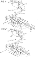
- the ophthalmic surgery apparatus comprises, overall, a laser unit 10 and an operating optic 11, for an operator whose eye has been shown diagrammatically at 12, and for an operating point shown schematically in 13.
- the laser unit 10 itself generally comprises a main laser with an infrared beam 15, with an operating laser, an auxiliary laser with a visible beam 16, or aiming laser, and a set of reflecting mirrors, detailed below, specific to superimposing said beams at the input of the operating optics 11.
- the operating laser 15 comprises for example on either side of a laser head 18 containing a bar of YAG doped with Neodymium, on the one hand a tank 19, with DYE or other saturable absorbent solution and concave mirror, and on the other hand a standard of PEROT-FABRY 20.
- a diaphragm 21 is provided between the laser head 18 and the tank 19.
- the axis AI of the beam of the operating laser 15 thus formed is successively folded over by a deflection mirror 22, which, for reasons which will appear below, is a dichroic mirror, that is to say a mirror which, reflecting for infrared radiation, allows visible radiation to pass through, a deflection mirror 23, and, at the entrance to the operating optics 11, a deflection mirror 24.
- a deflection mirror 22 which, for reasons which will appear below, is a dichroic mirror, that is to say a mirror which, reflecting for infrared radiation, allows visible radiation to pass through, a deflection mirror 23, and, at the entrance to the operating optics 11, a deflection mirror 24.
- These mirrors 22, 23, 24 are all mobile mirrors.
- the aiming laser 16 is for example a helium-neon laser.
- the axis A2 of its beam is folded towards the deflection mirror 23, through the deflection mirror 22.
- the beams of the operating laser 15 and the aiming laser 16 are therefore superimposed.
- the operating optic 11 comprises, overall, a transfer arm 27, which is formed of sections successively articulated one after the other, and a slit lamp 28, of which the microscope has been shown diagrammatically at 29 .
- It further comprises, on its optical path, a focusing lens 30.
- the transfer arm 27 is equipped with deflection mirrors 32.
- FIGS. 1, 2 it thus comprises, at least, a deflection mirror 32, opposite the deflection mirror 24 forming the output mirror of the laser unit 10, and a deflection mirror 32 to the base of the vertical leg of the slit lamp 28.
- it also optionally includes, internally, a certain number of deflection mirrors 34.
- the beam expander of the operating laser 15 and that of the aiming laser 16 have in common their output lens.
- the beam expander used has an input lens 36, between the PEROT-FABRY standard 20 and the return mirror 22, and an output lens 37, between the mirrors 23 and 24.
- the input lens 36 is a divergent lens; on the other hand, the output lens 37 is a converging lens.
- lens is understood as well here a unitary lens as a group of lenses joined together to jointly form the optical equivalent of a single lens.
- the beam expander of the sighting laser 16 comprises an input lens 38, between its laser head and the deflection mirror 25, and its output lens consists of the preceding output lens 37.
- the input lens 38 is a converging lens.
- the output lens 37 common to the beam expanders of the two lasers can be arranged as close as possible to the return mirror 24 forming the output mirror of the laser unit 10.
- the two laser beam expanders have a common section, counting from the return mirror 22, and it is within this common section of these beam expanders that the superposition of the beams of said lasers at the input of the operating optics 11.
- the deflection mirror 25 can advantageously be a fixed mirror.
- each of the diasporameters 40 is itself replaced by a simple lens which, inducing a prism when it is eccentric, is mounted movable in its plane, that is to say perpendicular to the axis A2 of the corresponding beam.
- the return mirror 24 makes it possible, in parallel, to make up for an angular error between the laser unit 10 and the operating optics 11.
- the aiming laser 16 can also serve as an alignment laser for the operating laser 15.
- two deflecting mirrors 42 arranged on the other side of the laser head of the aiming laser 16 relative to the beam expander associated therewith, fold back towards the operating laser 15 the axis A2 of the beam of the aiming laser 16, with the interposition, as before, either of two successive diasporameters 43, or of two successive lenses each of which is mounted movable in its plane.
- the output lens common to the beam expander of the operating laser 15 and to the beam expander of the aiming laser 16 is formed by the focusing lens 30 of the optics 11.
- the previous lens 37 is eliminated, and the focusing lens 30 is established so as to simultaneously perform a dual function of output lens for the beam expander of lasers 15, 16, and of focusing lens for optics 11.
- a saturable absorbent is preferably provided between the return mirrors 23, 24 of the laser unit 10, to avoid super-radiances.
Landscapes
- Health & Medical Sciences (AREA)
- Optics & Photonics (AREA)
- Physics & Mathematics (AREA)
- Engineering & Computer Science (AREA)
- Ophthalmology & Optometry (AREA)
- Heart & Thoracic Surgery (AREA)
- Life Sciences & Earth Sciences (AREA)
- Mechanical Engineering (AREA)
- Surgery (AREA)
- Biomedical Technology (AREA)
- Plasma & Fusion (AREA)
- Vascular Medicine (AREA)
- Nuclear Medicine, Radiotherapy & Molecular Imaging (AREA)
- Animal Behavior & Ethology (AREA)
- General Health & Medical Sciences (AREA)
- Public Health (AREA)
- Veterinary Medicine (AREA)
- Laser Surgery Devices (AREA)
- Radiation-Therapy Devices (AREA)
- Prostheses (AREA)
Claims (7)
Priority Applications (1)
| Application Number | Priority Date | Filing Date | Title |
|---|---|---|---|
| AT82401760T ATE17183T1 (de) | 1981-10-02 | 1982-09-28 | Lasergeraet fuer ophthalmologische chirurgie. |
Applications Claiming Priority (2)
| Application Number | Priority Date | Filing Date | Title |
|---|---|---|---|
| FR8118612A FR2513873B1 (fr) | 1981-10-02 | 1981-10-02 | Appareil de chirurgie ophtalmologique a laser |
| FR8118612 | 1981-10-02 |
Publications (3)
| Publication Number | Publication Date |
|---|---|
| EP0076740A2 EP0076740A2 (de) | 1983-04-13 |
| EP0076740A3 EP0076740A3 (en) | 1984-01-11 |
| EP0076740B1 true EP0076740B1 (de) | 1986-01-02 |
Family
ID=9262699
Family Applications (1)
| Application Number | Title | Priority Date | Filing Date |
|---|---|---|---|
| EP82401760A Expired EP0076740B1 (de) | 1981-10-02 | 1982-09-28 | Lasergerät für ophthalmologische Chirurgie |
Country Status (7)
| Country | Link |
|---|---|
| US (1) | US4517980A (de) |
| EP (1) | EP0076740B1 (de) |
| JP (1) | JPS5869557A (de) |
| AT (1) | ATE17183T1 (de) |
| CA (1) | CA1188372A (de) |
| DE (1) | DE3268315D1 (de) |
| FR (1) | FR2513873B1 (de) |
Families Citing this family (42)
| Publication number | Priority date | Publication date | Assignee | Title |
|---|---|---|---|---|
| FR2524298A1 (fr) * | 1982-04-01 | 1983-10-07 | Essilor Int | Appareil de chirurgie ophtalmologique a laser |
| JPS5985657A (ja) * | 1982-11-06 | 1984-05-17 | 日本赤外線工業株式会社 | レ−ザ照射装置 |
| DE3335810A1 (de) * | 1983-10-01 | 1985-04-18 | Fa. Carl Zeiss, 7920 Heidenheim | Optisches system fuer therapeutische laserlichtanwendung |
| US4561436A (en) * | 1983-10-28 | 1985-12-31 | Cooper Lasersonics, Inc. | Optical system for surgical ophthalmic laser instrument |
| US4601288A (en) * | 1984-02-24 | 1986-07-22 | Myers John D | Laser device and method |
| IL78416A0 (en) * | 1986-04-03 | 1986-08-31 | Uzi Sharon | Laser surgery system |
| EP0293126A1 (de) * | 1987-05-20 | 1988-11-30 | Keeler Limited | Vorrichtung zur Photokoagulation |
| JPH01118106A (ja) * | 1987-10-30 | 1989-05-10 | Japan Aviation Electron Ind Ltd | 光ファイバ調芯固定方法 |
| US4764930A (en) * | 1988-01-27 | 1988-08-16 | Intelligent Surgical Lasers | Multiwavelength laser source |
| US4901718A (en) * | 1988-02-02 | 1990-02-20 | Intelligent Surgical Lasers | 3-Dimensional laser beam guidance system |
| US4848340A (en) * | 1988-02-10 | 1989-07-18 | Intelligent Surgical Lasers | Eyetracker and method of use |
| US4881808A (en) * | 1988-02-10 | 1989-11-21 | Intelligent Surgical Lasers | Imaging system for surgical lasers |
| US5185758A (en) * | 1989-11-28 | 1993-02-09 | Massachusetts Institute Of Technology | Multiple-laser pump optical system |
| US5048953A (en) * | 1990-02-05 | 1991-09-17 | Industrial Technology Research Institute | Optical collimating, laser ray target position indicating and laser ray absorbing device of a laser system |
| US5331649A (en) * | 1991-07-10 | 1994-07-19 | Alson Surgical, Inc. | Multiple wavelength laser system |
| JP3164236B2 (ja) * | 1991-10-04 | 2001-05-08 | 株式会社ニデック | 光治療装置 |
| US5246435A (en) * | 1992-02-25 | 1993-09-21 | Intelligent Surgical Lasers | Method for removing cataractous material |
| US7655002B2 (en) * | 1996-03-21 | 2010-02-02 | Second Sight Laser Technologies, Inc. | Lenticular refractive surgery of presbyopia, other refractive errors, and cataract retardation |
| US5822035A (en) * | 1996-08-30 | 1998-10-13 | Heidelberg Engineering Optische Messysteme Gmbh | Ellipsometer |
| US6324191B1 (en) | 2000-01-12 | 2001-11-27 | Intralase Corp. | Oscillator with mode control |
| DE10332074A1 (de) * | 2003-07-11 | 2005-02-10 | Carl Zeiss Jena Gmbh | Anordnung zur Direkteinkopplung eines Lasers, vorzugsweise eines Kurzpulslasers |
| US7402159B2 (en) * | 2004-03-01 | 2008-07-22 | 20/10 Perfect Vision Optische Geraete Gmbh | System and method for positioning a patient for laser surgery |
| US9889043B2 (en) | 2006-01-20 | 2018-02-13 | Lensar, Inc. | System and apparatus for delivering a laser beam to the lens of an eye |
| US10842675B2 (en) | 2006-01-20 | 2020-11-24 | Lensar, Inc. | System and method for treating the structure of the human lens with a laser |
| US9545338B2 (en) | 2006-01-20 | 2017-01-17 | Lensar, Llc. | System and method for improving the accommodative amplitude and increasing the refractive power of the human lens with a laser |
| US8262646B2 (en) | 2006-01-20 | 2012-09-11 | Lensar, Inc. | System and method for providing the shaped structural weakening of the human lens with a laser |
| US20070173796A1 (en) * | 2006-01-25 | 2007-07-26 | Ralf Kessler | Device and method for calibrating a laser system |
| KR100761238B1 (ko) * | 2007-03-13 | 2007-09-27 | 에스엔유 프리시젼 주식회사 | 레이저빔 가공장치 |
| US8480659B2 (en) | 2008-07-25 | 2013-07-09 | Lensar, Inc. | Method and system for removal and replacement of lens material from the lens of an eye |
| US8500723B2 (en) | 2008-07-25 | 2013-08-06 | Lensar, Inc. | Liquid filled index matching device for ophthalmic laser procedures |
| CN102647954B (zh) | 2009-07-24 | 2016-02-03 | 能斯雅有限公司 | 一种为眼睛晶状体提供激光照射图案的系统和方法 |
| US8382745B2 (en) | 2009-07-24 | 2013-02-26 | Lensar, Inc. | Laser system and method for astigmatic corrections in association with cataract treatment |
| WO2011011788A1 (en) | 2009-07-24 | 2011-01-27 | Lensar, Inc. | System and method for performing ladar assisted procedures on the lens of an eye |
| US8617146B2 (en) | 2009-07-24 | 2013-12-31 | Lensar, Inc. | Laser system and method for correction of induced astigmatism |
| US8758332B2 (en) | 2009-07-24 | 2014-06-24 | Lensar, Inc. | Laser system and method for performing and sealing corneal incisions in the eye |
| WO2011094678A1 (en) | 2010-02-01 | 2011-08-04 | Lensar, Inc. | Purkinjie image-based alignment of suction ring in ophthalmic applications |
| CN106974614B (zh) | 2010-10-15 | 2019-04-26 | 雷萨公司 | 眼睛内部的结构的扫描控制照明的系统和方法 |
| USD694890S1 (en) | 2010-10-15 | 2013-12-03 | Lensar, Inc. | Laser system for treatment of the eye |
| USD695408S1 (en) | 2010-10-15 | 2013-12-10 | Lensar, Inc. | Laser system for treatment of the eye |
| US10463541B2 (en) | 2011-03-25 | 2019-11-05 | Lensar, Inc. | System and method for correcting astigmatism using multiple paired arcuate laser generated corneal incisions |
| US9393154B2 (en) | 2011-10-28 | 2016-07-19 | Raymond I Myers | Laser methods for creating an antioxidant sink in the crystalline lens for the maintenance of eye health and physiology and slowing presbyopia development |
| US9849034B2 (en) | 2011-11-07 | 2017-12-26 | Alcon Research, Ltd. | Retinal laser surgery |
Family Cites Families (9)
| Publication number | Priority date | Publication date | Assignee | Title |
|---|---|---|---|---|
| US3710798A (en) * | 1971-08-30 | 1973-01-16 | American Optical Corp | Laser system for microsurgery |
| CH562078A5 (de) * | 1972-05-30 | 1975-05-30 | Omega Brandt & Freres Sa Louis | |
| JPS5919798B2 (ja) * | 1974-11-01 | 1984-05-08 | 株式会社日立製作所 | レ−ザ加工装置 |
| FR2306550A1 (fr) * | 1975-04-03 | 1976-10-29 | Cilas | Generateur laser |
| FR2442622A1 (fr) * | 1978-06-08 | 1980-06-27 | Aron Rosa Daniele | Appareil de chirurgie ophtalmologique |
| US4289378A (en) * | 1978-06-21 | 1981-09-15 | Ernst Remy | Apparatus for adjusting the focal point of an operating laser beam focused by an objective |
| JPS55156687A (en) * | 1979-05-23 | 1980-12-05 | Mitsubishi Electric Corp | Laser working apparatus |
| DE3069080D1 (en) * | 1979-11-28 | 1984-10-04 | Lasag Ag | Observation device for eye-treatment |
| US4408602A (en) * | 1981-01-14 | 1983-10-11 | Asahi Kogaku Kogyo Kabushiki Kaisha | Laser knife device |
-
1981
- 1981-10-02 FR FR8118612A patent/FR2513873B1/fr not_active Expired
-
1982
- 1982-09-28 DE DE8282401760T patent/DE3268315D1/de not_active Expired
- 1982-09-28 AT AT82401760T patent/ATE17183T1/de active
- 1982-09-28 EP EP82401760A patent/EP0076740B1/de not_active Expired
- 1982-09-29 CA CA000412429A patent/CA1188372A/fr not_active Expired
- 1982-09-30 US US06/429,962 patent/US4517980A/en not_active Expired - Fee Related
- 1982-10-01 JP JP57173131A patent/JPS5869557A/ja active Pending
Also Published As
| Publication number | Publication date |
|---|---|
| FR2513873B1 (fr) | 1985-10-25 |
| EP0076740A3 (en) | 1984-01-11 |
| JPS5869557A (ja) | 1983-04-25 |
| CA1188372A (fr) | 1985-06-04 |
| FR2513873A1 (fr) | 1983-04-08 |
| US4517980A (en) | 1985-05-21 |
| EP0076740A2 (de) | 1983-04-13 |
| ATE17183T1 (de) | 1986-01-15 |
| DE3268315D1 (en) | 1986-02-13 |
Similar Documents
| Publication | Publication Date | Title |
|---|---|---|
| EP0076740B1 (de) | Lasergerät für ophthalmologische Chirurgie | |
| EP0007256B1 (de) | Gerät für die Augenchirurgie | |
| EP0030210B1 (de) | Beobachtungsgerät zur Augenbehandlung | |
| CH676419A5 (de) | ||
| CH645801A5 (fr) | Tete optique d'une installation pour l'observation et le traitement par rayonnement laser de l'oeil. | |
| EP2576127A1 (de) | Gerät zur glasfaseroptischen bearbeitung von ätzrillen, die beginnende risse bilden | |
| EP0299836A1 (de) | Optisches System und dieses System enthaltendes chirurgisches Gerät | |
| FR2541468A1 (fr) | Dispositif d'alignement d'un faisceau laser par l'intermediaire de moyens optiques de visee, procede de reperage de l'axe d'emission du faisceau laser et procede de mise en oeuvre du dispositif, pour controler l'alignement | |
| EP0382613B1 (de) | Mechanisch-optische Vorrichtung für eine drehbare optische Verbindung | |
| FR2727214A1 (fr) | Dispositif de stereomicroscope a objectif commun et de chemins de rayons d'observation stereoscopique utilise dans le domaine de la microchirurgie en ophtalmologie | |
| FR2759208A1 (fr) | Dispositif de controle du pointage et de la focalisation des chaines laser sur une cible | |
| EP3743025A1 (de) | Vorrichtung zum schneiden eines menschlichen oder tierischen gewebes mit einem optischen koppler | |
| EP0232347A1 (de) | Chirurgische laservorrichtung zur photoablation der augenhornhaut | |
| EP0089921B1 (de) | Optischer Kopf einer Vorrichtung zur Beobachtung und Behandlung des Auges mit Laserstrahlung | |
| FR2661371A1 (fr) | Procede et dispositif de restauration d'óoeuvre d'art. | |
| FR2554283A1 (fr) | Systeme laser | |
| FR2594686A1 (fr) | Dispositif pour effectuer une incision rectiligne dans un oeil a traiter | |
| CA3096228A1 (fr) | Appareil de traitement d'un tissu incluant des systemes optiques originaux de deviation et de focalisation d'un faisceau l.a.s.e.r. | |
| EP4236885A1 (de) | System zum schneiden von augengewebe in elementare teile | |
| EP0362764B1 (de) | Vorrichtung zur Erzeugung einer Umhüllung von Kraftstrahlen | |
| FR2458272A2 (fr) | Vitreotome a laser a impulsions picoseconde | |
| WO2022207900A1 (fr) | Systeme de decoupe d'un tissu en portions par generation de bulles de gaz oblongues | |
| EP3784181B1 (de) | System zur laserphotokoagulation der netzhaut | |
| EP0364801A1 (de) | Vorrichtung zur chirurgischen Behandlung einer Stelle im Auge | |
| CA3202454A1 (fr) | Dispositif d'amplification d'un faisceau laser |
Legal Events
| Date | Code | Title | Description |
|---|---|---|---|
| PUAI | Public reference made under article 153(3) epc to a published international application that has entered the european phase |
Free format text: ORIGINAL CODE: 0009012 |
|
| AK | Designated contracting states |
Designated state(s): AT BE CH DE GB IT LI LU NL SE |
|
| PUAL | Search report despatched |
Free format text: ORIGINAL CODE: 0009013 |
|
| AK | Designated contracting states |
Designated state(s): AT BE CH DE GB IT LI LU NL SE |
|
| 17P | Request for examination filed |
Effective date: 19840203 |
|
| GRAA | (expected) grant |
Free format text: ORIGINAL CODE: 0009210 |
|
| RAP1 | Party data changed (applicant data changed or rights of an application transferred) |
Owner name: SYNTHELABO |
|
| AK | Designated contracting states |
Designated state(s): AT BE CH DE GB IT LI LU NL SE |
|
| REF | Corresponds to: |
Ref document number: 17183 Country of ref document: AT Date of ref document: 19860115 Kind code of ref document: T |
|
| REF | Corresponds to: |
Ref document number: 3268315 Country of ref document: DE Date of ref document: 19860213 |
|
| ITF | It: translation for a ep patent filed |
Owner name: FUMERO BREVETTI S.N.C. |
|
| PLBE | No opposition filed within time limit |
Free format text: ORIGINAL CODE: 0009261 |
|
| STAA | Information on the status of an ep patent application or granted ep patent |
Free format text: STATUS: NO OPPOSITION FILED WITHIN TIME LIMIT |
|
| 26N | No opposition filed | ||
| ITTA | It: last paid annual fee | ||
| PGFP | Annual fee paid to national office [announced via postgrant information from national office to epo] |
Ref country code: BE Payment date: 19920706 Year of fee payment: 11 |
|
| PGFP | Annual fee paid to national office [announced via postgrant information from national office to epo] |
Ref country code: LU Payment date: 19920715 Year of fee payment: 11 |
|
| PGFP | Annual fee paid to national office [announced via postgrant information from national office to epo] |
Ref country code: SE Payment date: 19920813 Year of fee payment: 11 |
|
| PGFP | Annual fee paid to national office [announced via postgrant information from national office to epo] |
Ref country code: AT Payment date: 19920827 Year of fee payment: 11 |
|
| PGFP | Annual fee paid to national office [announced via postgrant information from national office to epo] |
Ref country code: GB Payment date: 19920916 Year of fee payment: 11 |
|
| PGFP | Annual fee paid to national office [announced via postgrant information from national office to epo] |
Ref country code: CH Payment date: 19920929 Year of fee payment: 11 |
|
| PGFP | Annual fee paid to national office [announced via postgrant information from national office to epo] |
Ref country code: NL Payment date: 19920930 Year of fee payment: 11 |
|
| PGFP | Annual fee paid to national office [announced via postgrant information from national office to epo] |
Ref country code: DE Payment date: 19921130 Year of fee payment: 11 |
|
| EPTA | Lu: last paid annual fee | ||
| PG25 | Lapsed in a contracting state [announced via postgrant information from national office to epo] |
Ref country code: LU Free format text: LAPSE BECAUSE OF NON-PAYMENT OF DUE FEES Effective date: 19930928 Ref country code: GB Effective date: 19930928 Ref country code: AT Effective date: 19930928 |
|
| PG25 | Lapsed in a contracting state [announced via postgrant information from national office to epo] |
Ref country code: SE Effective date: 19930929 |
|
| PG25 | Lapsed in a contracting state [announced via postgrant information from national office to epo] |
Ref country code: LI Effective date: 19930930 Ref country code: CH Effective date: 19930930 Ref country code: BE Effective date: 19930930 |
|
| BERE | Be: lapsed |
Owner name: SYNTHELABO Effective date: 19930930 |
|
| PG25 | Lapsed in a contracting state [announced via postgrant information from national office to epo] |
Ref country code: NL Effective date: 19940401 |
|
| NLV4 | Nl: lapsed or anulled due to non-payment of the annual fee | ||
| GBPC | Gb: european patent ceased through non-payment of renewal fee |
Effective date: 19930928 |
|
| REG | Reference to a national code |
Ref country code: CH Ref legal event code: PL |
|
| PG25 | Lapsed in a contracting state [announced via postgrant information from national office to epo] |
Ref country code: DE Effective date: 19940601 |
|
| EUG | Se: european patent has lapsed |
Ref document number: 82401760.2 Effective date: 19940410 |