EP0075528A2 - Bandage pneumatique - Google Patents
Bandage pneumatique Download PDFInfo
- Publication number
- EP0075528A2 EP0075528A2 EP82630087A EP82630087A EP0075528A2 EP 0075528 A2 EP0075528 A2 EP 0075528A2 EP 82630087 A EP82630087 A EP 82630087A EP 82630087 A EP82630087 A EP 82630087A EP 0075528 A2 EP0075528 A2 EP 0075528A2
- Authority
- EP
- European Patent Office
- Prior art keywords
- cords
- gas absorbing
- cord
- reinforcing
- rubber
- Prior art date
- Legal status (The legal status is an assumption and is not a legal conclusion. Google has not performed a legal analysis and makes no representation as to the accuracy of the status listed.)
- Granted
Links
Images
Classifications
-
- B—PERFORMING OPERATIONS; TRANSPORTING
- B60—VEHICLES IN GENERAL
- B60C—VEHICLE TYRES; TYRE INFLATION; TYRE CHANGING; CONNECTING VALVES TO INFLATABLE ELASTIC BODIES IN GENERAL; DEVICES OR ARRANGEMENTS RELATED TO TYRES
- B60C9/00—Reinforcements or ply arrangement of pneumatic tyres
- B60C9/0042—Reinforcements made of synthetic materials
-
- B—PERFORMING OPERATIONS; TRANSPORTING
- B60—VEHICLES IN GENERAL
- B60C—VEHICLE TYRES; TYRE INFLATION; TYRE CHANGING; CONNECTING VALVES TO INFLATABLE ELASTIC BODIES IN GENERAL; DEVICES OR ARRANGEMENTS RELATED TO TYRES
- B60C5/00—Inflatable pneumatic tyres or inner tubes
- B60C5/12—Inflatable pneumatic tyres or inner tubes without separate inflatable inserts, e.g. tubeless tyres with transverse section open to the rim
- B60C5/14—Inflatable pneumatic tyres or inner tubes without separate inflatable inserts, e.g. tubeless tyres with transverse section open to the rim with impervious liner or coating on the inner wall of the tyre
-
- B—PERFORMING OPERATIONS; TRANSPORTING
- B60—VEHICLES IN GENERAL
- B60C—VEHICLE TYRES; TYRE INFLATION; TYRE CHANGING; CONNECTING VALVES TO INFLATABLE ELASTIC BODIES IN GENERAL; DEVICES OR ARRANGEMENTS RELATED TO TYRES
- B60C9/00—Reinforcements or ply arrangement of pneumatic tyres
- B60C9/02—Carcasses
- B60C9/04—Carcasses the reinforcing cords of each carcass ply arranged in a substantially parallel relationship
-
- B—PERFORMING OPERATIONS; TRANSPORTING
- B60—VEHICLES IN GENERAL
- B60C—VEHICLE TYRES; TYRE INFLATION; TYRE CHANGING; CONNECTING VALVES TO INFLATABLE ELASTIC BODIES IN GENERAL; DEVICES OR ARRANGEMENTS RELATED TO TYRES
- B60C19/00—Tyre parts or constructions not otherwise provided for
- B60C2019/008—Venting means, e.g. for expelling entrapped air
-
- Y—GENERAL TAGGING OF NEW TECHNOLOGICAL DEVELOPMENTS; GENERAL TAGGING OF CROSS-SECTIONAL TECHNOLOGIES SPANNING OVER SEVERAL SECTIONS OF THE IPC; TECHNICAL SUBJECTS COVERED BY FORMER USPC CROSS-REFERENCE ART COLLECTIONS [XRACs] AND DIGESTS
- Y10—TECHNICAL SUBJECTS COVERED BY FORMER USPC
- Y10S—TECHNICAL SUBJECTS COVERED BY FORMER USPC CROSS-REFERENCE ART COLLECTIONS [XRACs] AND DIGESTS
- Y10S57/00—Textiles: spinning, twisting, and twining
- Y10S57/902—Reinforcing or tire cords
-
- Y—GENERAL TAGGING OF NEW TECHNOLOGICAL DEVELOPMENTS; GENERAL TAGGING OF CROSS-SECTIONAL TECHNOLOGIES SPANNING OVER SEVERAL SECTIONS OF THE IPC; TECHNICAL SUBJECTS COVERED BY FORMER USPC CROSS-REFERENCE ART COLLECTIONS [XRACs] AND DIGESTS
- Y10—TECHNICAL SUBJECTS COVERED BY FORMER USPC
- Y10T—TECHNICAL SUBJECTS COVERED BY FORMER US CLASSIFICATION
- Y10T152/00—Resilient tires and wheels
- Y10T152/10—Tires, resilient
- Y10T152/10495—Pneumatic tire or inner tube
- Y10T152/10855—Characterized by the carcass, carcass material, or physical arrangement of the carcass materials
- Y10T152/10873—Characterized by the carcass, carcass material, or physical arrangement of the carcass materials with two or more differing cord materials
-
- Y—GENERAL TAGGING OF NEW TECHNOLOGICAL DEVELOPMENTS; GENERAL TAGGING OF CROSS-SECTIONAL TECHNOLOGIES SPANNING OVER SEVERAL SECTIONS OF THE IPC; TECHNICAL SUBJECTS COVERED BY FORMER USPC CROSS-REFERENCE ART COLLECTIONS [XRACs] AND DIGESTS
- Y10—TECHNICAL SUBJECTS COVERED BY FORMER USPC
- Y10T—TECHNICAL SUBJECTS COVERED BY FORMER US CLASSIFICATION
- Y10T428/00—Stock material or miscellaneous articles
- Y10T428/29—Coated or structually defined flake, particle, cell, strand, strand portion, rod, filament, macroscopic fiber or mass thereof
- Y10T428/2913—Rod, strand, filament or fiber
- Y10T428/2933—Coated or with bond, impregnation or core
- Y10T428/294—Coated or with bond, impregnation or core including metal or compound thereof [excluding glass, ceramic and asbestos]
- Y10T428/296—Rubber, cellulosic or silicic material in coating
-
- Y—GENERAL TAGGING OF NEW TECHNOLOGICAL DEVELOPMENTS; GENERAL TAGGING OF CROSS-SECTIONAL TECHNOLOGIES SPANNING OVER SEVERAL SECTIONS OF THE IPC; TECHNICAL SUBJECTS COVERED BY FORMER USPC CROSS-REFERENCE ART COLLECTIONS [XRACs] AND DIGESTS
- Y10—TECHNICAL SUBJECTS COVERED BY FORMER USPC
- Y10T—TECHNICAL SUBJECTS COVERED BY FORMER US CLASSIFICATION
- Y10T428/00—Stock material or miscellaneous articles
- Y10T428/29—Coated or structually defined flake, particle, cell, strand, strand portion, rod, filament, macroscopic fiber or mass thereof
- Y10T428/2913—Rod, strand, filament or fiber
- Y10T428/2933—Coated or with bond, impregnation or core
- Y10T428/2964—Artificial fiber or filament
- Y10T428/2965—Cellulosic
-
- Y—GENERAL TAGGING OF NEW TECHNOLOGICAL DEVELOPMENTS; GENERAL TAGGING OF CROSS-SECTIONAL TECHNOLOGIES SPANNING OVER SEVERAL SECTIONS OF THE IPC; TECHNICAL SUBJECTS COVERED BY FORMER USPC CROSS-REFERENCE ART COLLECTIONS [XRACs] AND DIGESTS
- Y10—TECHNICAL SUBJECTS COVERED BY FORMER USPC
- Y10T—TECHNICAL SUBJECTS COVERED BY FORMER US CLASSIFICATION
- Y10T428/00—Stock material or miscellaneous articles
- Y10T428/29—Coated or structually defined flake, particle, cell, strand, strand portion, rod, filament, macroscopic fiber or mass thereof
- Y10T428/2913—Rod, strand, filament or fiber
- Y10T428/2933—Coated or with bond, impregnation or core
- Y10T428/2964—Artificial fiber or filament
- Y10T428/2967—Synthetic resin or polymer
- Y10T428/2969—Polyamide, polyimide or polyester
Definitions
- This invention relates to pneumatic tires and more particularly to a novel and improved tire cord fabric and the use thereof in a pneumatic tire to reduce defects in tires known as blows.
- tire reinforcement cords contain passages extending generally throughout the length of the cord and lying between and bounded by the filaments of which the cords are made and that air or other gases can travel along such passages. It has been observed that the treatment of tire reinforcement cords of the continuous synthetic resin filament materials such as polyester and nylon tend to reduce the cross sectional area of the interfilamentary passages significantly. Treatments which have this effect are generally characterized by the stretching of heated cords which may result in a reduction of a cross sectional area of the individual filaments and a compacting of the filaments more closely to one another.
- any air trapped within the tire or any gases generated during the vulcanization of the tire may be sufficient in volume to prevent the development of a satisfactory bond between the rubber material and the reinforcing cords within the tire or may break such bonds by forcing a separation between the rubber and the reinforcement cords.
- the resulting defects are known as blisters or blows. Examples of attempts to minimize such blisters or blows are described in United States Patents Nos. 2,541,506 and 3,552,468.
- a pneumatic tire is provided with at least one reinforcement ply wherein the reinforcement ply includes a plurality of reinforcing cords embedded in rubber or rubber-like material, the reinforcing cords extending in parallel spaced apart relation.
- the reinforcing ply further includes a plurality of gas absorbing cords extending parallel to and disposed between the reinforcing cords in spaced relation thereto with each gas absorbing cord lying generally in the same plane as that defined by the reinforcing cords on opposite sides thereof.
- Each gas absorbing cord consists of a multiplicity of staple filaments of a material or materials selected from the group consisting of nylon, rayon, polyester or glass and being of a diameter no greater than one-third the diameter of one of the reinforcing cords and having a break strength no greater than about 10 percent of the break strength of the reinforcing cords.
- Each gas absorbing cord is completely surrounded by rubber or rubber-like material forming the ply, and the gas absorbing cords are located alongside only every third to sixth reinforcing cord.
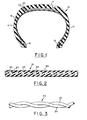
- a pneumatic tire generally indicated at 10, which comprises a pair of sidewall portions 12 terminating at their radially outer ends in a tread portion 14 and at their radially inner ends in a pair of beads 16.
- radially means “in a direction radially of the tire rotational axis”
- axially means in the direction of the rotational axis of the tire.
- the tire further comprises at least one reinforcement ply 18 connected to each of the beads 16 and extending through the sidewalls of the tire and under the . tread portion 14.
- the tire may have one or more of such reinforcement plies which are generally referred to as carcass plies.
- the tire 10 may further include additional reinforcing plies in the form of one or more breaker or belt plies 20, 22 disposed in the crown region of the tire between the carcass ply 18 and the tread 14.
- the tire 10 may be what is commonly referred to as bias, bias belted, or radial ply construction.
- the reinforcing ply 18 is composed of a plurality of reinforcing cords extending in parallel spaced apart relation.
- these reinforcing cords extend at a suitable angle to the mid-circumferential center plane of the tire at the circumferential centerline of the carcass ply 18, which angle may be, for example, from 25 to 40 degrees.
- the cords of the carcass ply 18 will extend substantially radially of the tire, for example, at an angle from 80 to 90 degrees to the mid-circumferential center plane of the tire.
- the breaker or belt plies such as 20 and 22 shown in Figure 1 each also include a plurality of reinforcing cords extending in parallel spaced apart relation.
- the cords will extend at a relatively low angle, for example, 15 to 25 degrees when the belt plies 20, 22 are used in combination with a radial ply carcass and at a somewhat higher angle, perhaps 25 to 35 degrees when used in conjunction with a bias ply carcass either as a belt or as breaker plies.
- the cords will have an angle at the mid-circumferential centerline of the tire which is normally at least 5 degrees less than the corresponding angle of the carcass ply or plies, and where used as a breaker in conjunction with a bias tire will have an angle at the mid-circumferential centerline of the tire which is equal or approximately equal to the corresponding angle of the carcass plies.
- the ply 18 comprises a plurality of reinforcing cords 24 disposed in parallel spaced apart relation and embedded in a matrix of rubber or rubber-like material 26, preferably by a conventional calendering process wherein the fabric is passed between rolls which press rubber between the cords 24 and coat the array of cords on both sides thereof with rubber.
- the ply 18 also includes a plurality of gas absorbing cords 30 with each gas absorbing cord 30 extending parallel to and being disposed between a pair of reinforcing cords 24 in spaced relation thereto.
- each gas absorbing cord lies generally in the same plane as that defined by the reinforcing cords on opposite sides thereof so as also to be embedded in rubber or rubber-like material. It should also be noted, as is apparent from Figure 1, that the ends of each of the reinforcement and gas absorbing cords are embedded in rubber and are not in communication with the exterior of the tire.
- the reinforcing cords 24 may be of any material or construction suitable for the reinforcement of a pneumatic tire and the term "cord" is used herein, and in the appended claims, to indicate any strength member suitable for the reinforcement of a pneumatic tire.
- the invention has particular utility where the reinforcing cords are formed of a single yarn or multiple yarns twisted together and wherein each yarn is composed of continuous filaments of a thermoplastic material such as nylon or polyester of a type suitable for the reinforcement of a pneumatic tire.
- each of the gas absorbing cords 30 is entirely surrounded by rubber.
- Each gas absorbing cord 30 consists of a single yarn or as shown in Figure 3, a plurality of yarns, such as at 32 and 34, twisted together.
- the yarn or yarns of each cord 30 is composed of staple fibers of material selected from the group consisting of rayon, nylon, polyester or glass with the staple fibers having a length of between one-half inch and two inches.
- staple fibers of material selected from the group consisting of rayon, nylon, polyester or glass with the staple fibers having a length of between one-half inch and two inches.
- the terms "rayon,” “nylon,” “polyester,” or “glass” as used herein and in the appended claims are intended to cover any such material commonly referred to by such terms and suitable for the use in a pneumatic tire such as those that are commonly known and used presently in the reinforcement of pneumatic tires.
- one gas absorbing cord 30 is provided and located alongside only every third to sixth reinforcing cord.
- the gas absorbing cords are spaced apart at equal distances laterally across the ply 18 and the distance between each next adjacent pair of gas absorbing cords is equal to the distance between either three, four, five or six reinforcing cords.
- the gas absorbing cords 30 are not intended to contribute to the reinforcement of the tire and thus are not reinforcing cords.
- each gas absorbing cord has a break strength of between about one pound (0.45 Kg) and one and one-half pounds (0.68 Kg) and which will be no greater than about one-fifth of the- breaking strength of a reinforcing cord 24.
- a break strength of about one pound (0.45 Kg) is necessary to assure that the gas absorbing cords will not break under the usual tensions to which they will be subjected during manufacture of the reinforcing ply.
- the material of the gas absorbing cords 30 is selected from the group consisting of rayon, nylon, polyester or glass. More particularly, the gas absorbing cord 30 may be made of a single one of these materials or a combination thereof.
- the yarn 32 is made of polyester staple filaments and the yarn 34 is made of rayon staple filaments.
- thermoplastic materials such as nylon or polyester when used in filamentary form in a tire cord will during a hot stretching operation tend to reduce the number of interfilamentary voids in the cord
- the fact that the gas absorbing cord 30 is composed of staple filaments assures that the interfilamentary spaces will remain in sufficient number to create the void spaces necessary for the accommodation of gases and air which is desired.
- the staple fibers assure that the cord 30 will have a sufficient elongation that even though a force is applied to the reinforcing cords 24 in excess of the break strength of the gas absorbing cord 30, the cords 30 may not break due to their higher elongation at break than that of the reinforcing cords 24.
- each gas absorbing cord is completely surrounded by the rubber 26 of the ply 18 so that the entire periphery and surface area of the cord is open to receive gases or air from the surrounding rubber.
- the diameter or gauge of each gas. absorbing cord 30 is substantially less than the distance between each pair of next adjacent reinforcing cords 24 and preferably has a diameter equal to no greater than about one third the distance between each next adjacent pair of reinforcing cords 24.
- a specific example of a reinforcing ply 18 which has provided a significant reduction in the number of blows or blisters in a tire in which it has been used is one wherein the ply 18 comprised reinforcing cords 24 which were each a singles yarn of 1300 denier having a twist of about 10 per inch (4 per cm.).
- the reinforcing cords 24 were equally spaced apart with 33 cords per inch (13 per cm.).
- Each reinforcing cord had a gauge or diameter of approximately .016 inches (0.4 mm) and the reinforcing cords were spaced apart or had a rivet of about .014 inches (.35 mm).
- the gas absorbing cords 30 each were composed of a yarn of polyester and a yarn of rayon each having a twist of about 7 turns per inch (2.8 per cm.) twisted together at about 7 turns per inch (2.8 cm.) to provide a cord of size 19 by the cotton count system (about 280 denier).
- Each gas absorbing cord had a gauge or diameter of about .004 inches (0.1 mm) and was located approximately midway between each pair of next adjacent reinforcing cords 24 so as to provide a space of about .006 inches (0.15 mm) between each gas absorbing cord and the next adjacent reinforcing cord.
- One gas absorbing cord 30 was located every fourth reinforcing cord 24.
- Each of the reinforcing cords 24 had a break strength of about 19 pounds (8.6 Kg) while the gas absorbing cords 30 had a break strength of approximately one and one-quarter pounds (0.6 Kg).
- the ply had a gauge or thickness of about .031 inches (0.8 mm) so that there was about .0075 inches (0.2 mm) of rubber or rubber-like material on each side of the array of reinforcing cords.
- a plurality of reinforcing cords are located in a common plane in parallel spaced apart relation with a gas absorbing cord as defined herein located alongside only every third to sixth reinforcing cord and with each the gas absorbing cords being in parallel, spaced relation to and lying in the same general plane as that of the two reinforcing cords on opposite sides thereof.
- the array of reinforcing cords and gas absorbing cords is then passed through a conventional calender to embed and completely surround each of the reinforcing and gas absorbing cords in rubber or rubber-like material to form the reinforcement ply.
- the reinforcement and gas absorbing cords may be held in the desired spaced relationship prior to the calendering operation by any suitable means, such as conventional pick or weft threads extending at right angles to the reinforcing and gas absorbing cords.
- the "fabric,” as the array of reinforcing and absorbing cords is commonly referred to, may be of the weftless type.
- the gas absorbing cords of the present invention eliminate any special twist operation for the reinforcing cords as is required in the aforementioned United States Patent No. 3,552,468. Also, the elimination of the cotton yarn in the cord of the aforementioned patent eliminates a bothersome environmental problem caused by an excess of cotton fibers in the air occurring during the twisting of the cotton yarn with the reinforcing cord yarns in a cord of the type described in the aforementioned patent.
Landscapes
- Engineering & Computer Science (AREA)
- Mechanical Engineering (AREA)
- Tires In General (AREA)
- Yarns And Mechanical Finishing Of Yarns Or Ropes (AREA)
- Tyre Moulding (AREA)
Applications Claiming Priority (2)
| Application Number | Priority Date | Filing Date | Title |
|---|---|---|---|
| US06/304,729 US4363346A (en) | 1981-09-23 | 1981-09-23 | Pneumatic tire including gas absorbing cords |
| US304729 | 1994-09-12 |
Publications (3)
| Publication Number | Publication Date |
|---|---|
| EP0075528A2 true EP0075528A2 (fr) | 1983-03-30 |
| EP0075528A3 EP0075528A3 (en) | 1984-07-18 |
| EP0075528B1 EP0075528B1 (fr) | 1986-12-03 |
Family
ID=23177730
Family Applications (1)
| Application Number | Title | Priority Date | Filing Date |
|---|---|---|---|
| EP82630087A Expired EP0075528B1 (fr) | 1981-09-23 | 1982-09-17 | Bandage pneumatique |
Country Status (6)
| Country | Link |
|---|---|
| US (1) | US4363346A (fr) |
| EP (1) | EP0075528B1 (fr) |
| JP (1) | JPS5867502A (fr) |
| BR (1) | BR8205415A (fr) |
| CA (1) | CA1170153A (fr) |
| DE (1) | DE3274530D1 (fr) |
Families Citing this family (23)
| Publication number | Priority date | Publication date | Assignee | Title |
|---|---|---|---|---|
| US4487814A (en) * | 1981-05-15 | 1984-12-11 | Dayco Corporation | Polymeric strip for a power transmission belt, belt made using such strip |
| JPS60164405U (ja) * | 1984-04-10 | 1985-10-31 | 三ツ星ベルト株式会社 | 自転車用タイヤ |
| USH1333H (en) | 1990-03-21 | 1994-07-05 | Helfer Farrel B | High strength reinforcement |
| US5318643A (en) * | 1990-03-21 | 1994-06-07 | The Goodyear Tire & Rubber Company | Vehicle tires including plies with high strength reinforcement |
| US5827381A (en) * | 1990-08-10 | 1998-10-27 | Bridgestone Corporation | Pneumatic radial tires including a tire component containing groups of reinforcing elements |
| US5221382A (en) * | 1991-05-10 | 1993-06-22 | The Goodyear Tire & Rubber Company | Pneumatic tire including gas absorbing cords |
| US6273160B1 (en) | 1992-10-13 | 2001-08-14 | The Goodyear Tire & Rubber Company | Tires with high strength reinforcement |
| FR2734764A1 (fr) * | 1995-05-30 | 1996-12-06 | Michelin & Cie | Pneumatique avec une nappe de renforcement a elements circonferentiels. |
| CA2310735A1 (fr) | 1997-12-09 | 1999-06-17 | William Frank Dunn | Capteur de pression pour pneumatique et procede associe |
| JP4188580B2 (ja) * | 2001-07-10 | 2008-11-26 | 住友ゴム工業株式会社 | 空気入りラジアルタイヤ |
| FR2954219A1 (fr) * | 2009-11-17 | 2011-06-24 | Michelin Soc Tech | Pneumatique comportant des cables d'armature de carcasse presentant des permeabilites differentes |
| FR2953449B1 (fr) * | 2009-12-03 | 2011-11-18 | Michelin Soc Tech | Pneumatique comportant une armature de carcasse constituee de cables et de tubes capillaires |
| FR2953450B1 (fr) * | 2009-12-04 | 2011-11-18 | Michelin Soc Tech | Pneumatique comportant des cables d'armature de carcasse presentant des permeabilites differentes |
| DE102010017444A1 (de) * | 2010-06-18 | 2011-12-22 | Continental Reifen Deutschland Gmbh | Fahrzeugluftreifen mit Luftabführungsfäden und Verfahren zur Herstellung einer elektrisch leitfähigen Beschichtung für die Luftabführungsfäden |
| BR112014005037B1 (pt) * | 2011-09-05 | 2021-01-26 | Sumitomo Rubber Industries, Ltd. | método de produção de pneumático e pneumático |
| US20130056128A1 (en) * | 2011-09-06 | 2013-03-07 | Carlo Kanz | Pneumatic tire with conductive bleeder cords |
| FR2984221B1 (fr) * | 2011-12-19 | 2014-05-16 | Michelin Soc Tech | Pneumatique comportant des cables d'armature de carcasse presentant une faible permeabilite, et des fils textiles associes a l'armature de carcasse |
| FR2984223B1 (fr) * | 2011-12-19 | 2014-04-18 | Michelin Soc Tech | Pneumatique comportant des cables d'armature de carcasse presentant une faible permeabilite, et des fils textiles associes a l'armature de carcasse |
| JP6152866B2 (ja) * | 2015-04-06 | 2017-06-28 | 横浜ゴム株式会社 | ゴム圧延部材の製造方法及び製造装置 |
| EP3307560B1 (fr) * | 2015-06-15 | 2020-11-11 | Bridgestone Americas Tire Operations, LLC | Pneu présentant un chemin de conductivité |
| JP6164268B2 (ja) * | 2015-09-30 | 2017-07-19 | 横浜ゴム株式会社 | 空気入りタイヤ及びその製造方法 |
| DE102016201926A1 (de) * | 2016-02-09 | 2017-08-10 | Continental Reifen Deutschland Gmbh | Verfahren zur Herstellung einer Materialbahn |
| WO2018070952A1 (fr) * | 2016-10-13 | 2018-04-19 | Kordsa Teknik Tekstil Anonim Sirketi | Bande de nappe de sommet comportant différentes constructions de renfort en nylon 6,6 |
Citations (7)
| Publication number | Priority date | Publication date | Assignee | Title |
|---|---|---|---|---|
| FR1310491A (fr) * | 1961-03-15 | 1962-11-30 | Kleber Colombes | Perfectionnements aux enveloppes de pneumatiques |
| FR1427189A (fr) * | 1964-12-23 | 1966-02-04 | Pneumatiques, Caoutchouc Manufacture Et Plastiques Kleber Colombes | Pneumatique sans chambre à air |
| US3552468A (en) * | 1967-09-12 | 1971-01-05 | Goodyear Tire & Rubber | Pneumatic tire with reduced susceptibility to defects |
| US3951719A (en) * | 1973-01-18 | 1976-04-20 | Hough Dean R | Vehicle tire construction and method of making same |
| FR2338813A1 (fr) * | 1976-01-21 | 1977-08-19 | Firestone Tire & Rubber Co | Pneumatique ceinture |
| DE2851526A1 (de) * | 1978-11-29 | 1980-06-12 | Olbo Textilwerke Gmbh | Flexibler koerper mit in ein gummiartiges elastisches material eingebetteten textilen festigkeitstraegern, beispielsweise foerderband, treibriemen oder automobilreifen radialer bauweise |
| DE8108375U1 (de) * | 1982-06-16 | Uniroyal Englebert Reifen GmbH, 5100 Aachen | Fahrzeugluftreifen |
Family Cites Families (3)
| Publication number | Priority date | Publication date | Assignee | Title |
|---|---|---|---|---|
| US1875517A (en) * | 1932-09-06 | Samuel a | ||
| US2541506A (en) * | 1949-04-29 | 1951-02-13 | Us Rubber Co | Method of building pneumatic tires |
| BE535372A (fr) * | 1954-02-10 |
-
1981
- 1981-09-23 US US06/304,729 patent/US4363346A/en not_active Expired - Lifetime
-
1982
- 1982-09-15 BR BR8205415A patent/BR8205415A/pt not_active IP Right Cessation
- 1982-09-15 CA CA000411426A patent/CA1170153A/fr not_active Expired
- 1982-09-17 DE DE8282630087T patent/DE3274530D1/de not_active Expired
- 1982-09-17 EP EP82630087A patent/EP0075528B1/fr not_active Expired
- 1982-09-21 JP JP57163300A patent/JPS5867502A/ja active Granted
Patent Citations (8)
| Publication number | Priority date | Publication date | Assignee | Title |
|---|---|---|---|---|
| DE8108375U1 (de) * | 1982-06-16 | Uniroyal Englebert Reifen GmbH, 5100 Aachen | Fahrzeugluftreifen | |
| FR1310491A (fr) * | 1961-03-15 | 1962-11-30 | Kleber Colombes | Perfectionnements aux enveloppes de pneumatiques |
| FR1427189A (fr) * | 1964-12-23 | 1966-02-04 | Pneumatiques, Caoutchouc Manufacture Et Plastiques Kleber Colombes | Pneumatique sans chambre à air |
| US3552468A (en) * | 1967-09-12 | 1971-01-05 | Goodyear Tire & Rubber | Pneumatic tire with reduced susceptibility to defects |
| US3661668A (en) * | 1967-09-12 | 1972-05-09 | Goodyear Tire & Rubber | Method of making a pneumatic tire with reduced susceptibility to blow or blister defects |
| US3951719A (en) * | 1973-01-18 | 1976-04-20 | Hough Dean R | Vehicle tire construction and method of making same |
| FR2338813A1 (fr) * | 1976-01-21 | 1977-08-19 | Firestone Tire & Rubber Co | Pneumatique ceinture |
| DE2851526A1 (de) * | 1978-11-29 | 1980-06-12 | Olbo Textilwerke Gmbh | Flexibler koerper mit in ein gummiartiges elastisches material eingebetteten textilen festigkeitstraegern, beispielsweise foerderband, treibriemen oder automobilreifen radialer bauweise |
Also Published As
| Publication number | Publication date |
|---|---|
| BR8205415A (pt) | 1983-08-23 |
| US4363346A (en) | 1982-12-14 |
| DE3274530D1 (en) | 1987-01-15 |
| EP0075528B1 (fr) | 1986-12-03 |
| JPS5867502A (ja) | 1983-04-22 |
| CA1170153A (fr) | 1984-07-03 |
| EP0075528A3 (en) | 1984-07-18 |
| JPH0112683B2 (fr) | 1989-03-01 |
Similar Documents
| Publication | Publication Date | Title |
|---|---|---|
| US4363346A (en) | Pneumatic tire including gas absorbing cords | |
| EP0514823B1 (fr) | Pneumatique comportant des cordes absorbantes le gaz | |
| CA1170127A (fr) | Corde d'armature etirable pour articles en elastomere | |
| US4284117A (en) | Steel belted radial ply tires with cap plies employing single yarn reinforcing elements | |
| US4073330A (en) | Tire cord fabrics for belts of belted pneumatic tires | |
| US4262726A (en) | Radial tire with a low angle carcass overlay ply | |
| US3612139A (en) | Novel bead structure for pneumatic tires | |
| US7188654B2 (en) | Ply with strength carriers embedded in a rubber mixture and vehicle pneumatic tires with a belt bandage thereof | |
| EP2604448B1 (fr) | Corde composite et pli de superposition pour pneu | |
| EP0016114B1 (fr) | Cordon composite de renforcement pour renforcer des articles élastomères et procédé de fabrication d'un pneu extansible à carcasse radiale | |
| CA2232494A1 (fr) | Cable metallique pour renforcer des articles en caoutchouc | |
| US20110259501A1 (en) | Hybrid cord in a belt ply for a pneumatic tire | |
| US3431962A (en) | Reinforcement for pneumatic tires and the like | |
| US4333507A (en) | Tire with composite reinforcement cord | |
| US3395744A (en) | Reinforcing fabric for tires | |
| US3516465A (en) | Reinforced tire | |
| US7032638B2 (en) | Tire with a protective crown ply made of very high twist aramid fiber | |
| US3661668A (en) | Method of making a pneumatic tire with reduced susceptibility to blow or blister defects | |
| US4458475A (en) | Composite reinforcement cord | |
| US3071919A (en) | Cable for use in reinforcing elastomeric product | |
| US3217778A (en) | Pneumatic cord tire | |
| US20100166993A1 (en) | Reinforcement layer made of hybrid cords for elastomeric products | |
| US3921691A (en) | Macrofilamentary yarns and rubber structures reinforced therewith | |
| IT202000014521A1 (it) | Pneumatico per ruote di veicoli | |
| CA1200745A (fr) | Toile mecanique tissee, et pneu qui la renferme |
Legal Events
| Date | Code | Title | Description |
|---|---|---|---|
| PUAI | Public reference made under article 153(3) epc to a published international application that has entered the european phase |
Free format text: ORIGINAL CODE: 0009012 |
|
| 17P | Request for examination filed |
Effective date: 19820924 |
|
| AK | Designated contracting states |
Designated state(s): DE FR GB IT LU |
|
| PUAL | Search report despatched |
Free format text: ORIGINAL CODE: 0009013 |
|
| AK | Designated contracting states |
Designated state(s): DE FR GB IT LU |
|
| GRAA | (expected) grant |
Free format text: ORIGINAL CODE: 0009210 |
|
| AK | Designated contracting states |
Kind code of ref document: B1 Designated state(s): DE FR GB IT LU |
|
| REF | Corresponds to: |
Ref document number: 3274530 Country of ref document: DE Date of ref document: 19870115 |
|
| ET | Fr: translation filed | ||
| ITF | It: translation for a ep patent filed |
Owner name: MODIANO & ASSOCIATI S.R.L. |
|
| PLBE | No opposition filed within time limit |
Free format text: ORIGINAL CODE: 0009261 |
|
| STAA | Information on the status of an ep patent application or granted ep patent |
Free format text: STATUS: NO OPPOSITION FILED WITHIN TIME LIMIT |
|
| 26N | No opposition filed | ||
| REG | Reference to a national code |
Ref country code: FR Ref legal event code: CL |
|
| ITTA | It: last paid annual fee | ||
| EPTA | Lu: last paid annual fee | ||
| PGFP | Annual fee paid to national office [announced via postgrant information from national office to epo] |
Ref country code: GB Payment date: 19990806 Year of fee payment: 18 |
|
| PGFP | Annual fee paid to national office [announced via postgrant information from national office to epo] |
Ref country code: LU Payment date: 19990813 Year of fee payment: 18 |
|
| PGFP | Annual fee paid to national office [announced via postgrant information from national office to epo] |
Ref country code: FR Payment date: 19990901 Year of fee payment: 18 |
|
| PGFP | Annual fee paid to national office [announced via postgrant information from national office to epo] |
Ref country code: DE Payment date: 19990927 Year of fee payment: 18 |
|
| PG25 | Lapsed in a contracting state [announced via postgrant information from national office to epo] |
Ref country code: LU Free format text: LAPSE BECAUSE OF NON-PAYMENT OF DUE FEES Effective date: 20000917 Ref country code: GB Free format text: LAPSE BECAUSE OF NON-PAYMENT OF DUE FEES Effective date: 20000917 |
|
| GBPC | Gb: european patent ceased through non-payment of renewal fee |
Effective date: 20000917 |
|
| PG25 | Lapsed in a contracting state [announced via postgrant information from national office to epo] |
Ref country code: FR Free format text: LAPSE BECAUSE OF NON-PAYMENT OF DUE FEES Effective date: 20010531 |
|
| PG25 | Lapsed in a contracting state [announced via postgrant information from national office to epo] |
Ref country code: DE Free format text: LAPSE BECAUSE OF NON-PAYMENT OF DUE FEES Effective date: 20010601 |
|
| REG | Reference to a national code |
Ref country code: FR Ref legal event code: ST |