EP0075474A2 - Verfahren und Vorrichtung zum Schlitzen thermoplastischer Filme - Google Patents
Verfahren und Vorrichtung zum Schlitzen thermoplastischer Filme Download PDFInfo
- Publication number
- EP0075474A2 EP0075474A2 EP82304942A EP82304942A EP0075474A2 EP 0075474 A2 EP0075474 A2 EP 0075474A2 EP 82304942 A EP82304942 A EP 82304942A EP 82304942 A EP82304942 A EP 82304942A EP 0075474 A2 EP0075474 A2 EP 0075474A2
- Authority
- EP
- European Patent Office
- Prior art keywords
- film
- roll
- cutting edges
- polymeric material
- cutter
- Prior art date
- Legal status (The legal status is an assumption and is not a legal conclusion. Google has not performed a legal analysis and makes no representation as to the accuracy of the status listed.)
- Granted
Links
Images
Classifications
-
- B—PERFORMING OPERATIONS; TRANSPORTING
- B26—HAND CUTTING TOOLS; CUTTING; SEVERING
- B26F—PERFORATING; PUNCHING; CUTTING-OUT; STAMPING-OUT; SEVERING BY MEANS OTHER THAN CUTTING
- B26F3/00—Severing by means other than cutting; Apparatus therefor
- B26F3/06—Severing by using heat
- B26F3/08—Severing by using heat with heated members
- B26F3/10—Severing by using heat with heated members with heated rollers or discs
-
- Y—GENERAL TAGGING OF NEW TECHNOLOGICAL DEVELOPMENTS; GENERAL TAGGING OF CROSS-SECTIONAL TECHNOLOGIES SPANNING OVER SEVERAL SECTIONS OF THE IPC; TECHNICAL SUBJECTS COVERED BY FORMER USPC CROSS-REFERENCE ART COLLECTIONS [XRACs] AND DIGESTS
- Y10—TECHNICAL SUBJECTS COVERED BY FORMER USPC
- Y10T—TECHNICAL SUBJECTS COVERED BY FORMER US CLASSIFICATION
- Y10T83/00—Cutting
- Y10T83/04—Processes
- Y10T83/0405—With preparatory or simultaneous ancillary treatment of work
- Y10T83/041—By heating or cooling
- Y10T83/0414—At localized area [e.g., line of separation]
-
- Y—GENERAL TAGGING OF NEW TECHNOLOGICAL DEVELOPMENTS; GENERAL TAGGING OF CROSS-SECTIONAL TECHNOLOGIES SPANNING OVER SEVERAL SECTIONS OF THE IPC; TECHNICAL SUBJECTS COVERED BY FORMER USPC CROSS-REFERENCE ART COLLECTIONS [XRACs] AND DIGESTS
- Y10—TECHNICAL SUBJECTS COVERED BY FORMER USPC
- Y10T—TECHNICAL SUBJECTS COVERED BY FORMER US CLASSIFICATION
- Y10T83/00—Cutting
- Y10T83/283—With means to control or modify temperature of apparatus or work
- Y10T83/293—Of tool
Definitions
- the present invention relates to a method of and an apparatus for providing a thermoplastic film with continuous or discrete slits extending in the longitudinal or transverse direction thereof.
- razor cut slitters and high-speed rotary cutters have been found to be disadvantageous in that their sharp cutting edges are liable to be worn out and become dull in a relatively short period of use when employed in slitting a non-stretched thermoplastic film, because the cutting edges undergo much abrasion by being forced along the film surface. With such worn-out or dull cutting edges, the film is locally stretched or sometimes cracked at portions adjacent to the slits formed, and hence is ruptured or torn apart at the defective slits as it is stretched into a reticular web.
- a score cut slitter circular cutting edges pressed against a hard peripheral surface of a roll are worn out at a rapid rate, moreover, the roll surface is liable to be damaged by the - cutting edges.
- shear cut slitters utilize a cooperating pair of bottom and top blades, a film is liable to be cracked at the ends of slits formed with the blades.
- Ordinary heat cut slitters have the drawback that slits formed with a hot blade are irregular in shape due to scratches made by cutting blades stained with fused film material sticking onto them, or are partly closed by rejoining.
- a method of slitting a continuous thermoplastic film comprising the steps of advancing the film longitudinally at a first speed along a peripheral surface of a roll rotating at a circumferential speed substantially equal to or slightly greater than said first speed, and slitting the film while being advanced by pressing, against said peripheral surface of said roll, cutting edges of a cutter rotating at substantially the same speed as said roll, characterized in that said peripheral surface comprises an elastic layer made of a polymeric material, that said cutting edges are heated above a temperature at which the thermoplastic film starts melting, and that the film and said elastic surface are cooled along their interface.
- an apparatus for slitting a continuous thermoplastic film comprising means for advancing the film longitudinally at a first speed, a roll rotatable at a circumferential speed substantially equal to or slightly greater than said first speed and having a peripheral surface along which the film is advanced, and a cutter disposed adjacent to said roll and rotatable at substantially the same speed as said roll, said cutter having cutting edges engageable with said peripheral surface of said roll, characterized in that said peripheral surface of said roll comprises an elastic layer made of a polymeric material, that means are provided for heating said cutting edges above a temperature at which the thermoplastic film starts melting, and that means are provided for cooling the contacting surface between the film and said elastic surface layer of said roll.
- the present invention seeks to provide a method and apparatus which eliminate the foregoing drawbacks associated with those in the prior art.
- the invention also seeks to provide a method of and an apparatus for slitting a non-stretched thermoplastic film which is suitable for use in the manufacture of a reticular web.
- the invention further seeks to provide a method and apparatus which can form a number of slits of uniform size and shape in a non-stretched thermoplastic film as close as possible so as to enable the film to be stretched at an increased magnification of stretch into a fine reticular web.
- the invention further seeks to provide a method of and an apparatus for slitting a thermoplastic film in which cutting means is protected from abrasive wear and hence is durable.
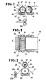
- Figures 1 and 2 show an apparatus 10 for providing a continuous thermoplastic film F with a number of continuous slits S extending longitudinally between the opposite edges of the film F.
- the apparatus 10 comprises a slitting unit 11 and a pair of pinch rollers 12a,12b disposed downstream of the slitting unit 11 and rotatable in cooperation with each other to advance the film F from through the slitting unit 11 to a spreading apparatus for manufacturing a reticular web or to an appropriate storing means (neither shown).
- the slitting unit 11 comprises a roll 13 rotatable about its own axis at a circumferential speed substantially equal to or slightly greater than the first speed or speed of feed of the film F.
- the roll 13 has a peripheral surface along which the film F is advanced as it is fed from an appropriate source (not shown).
- the peripheral surface comprises an elastic layer 14 made of a polymeric material, which usually is an elastomer, but may also be resin-impregnated leather or fabric, and at times can be leather or fabric itself.
- elastomers such as, for example, soft synthetic rubbers are preferable as they are easy to manufacture and available in a variety of hardness.
- the lower portion of the roll 13 is immersed in a cooling liquid 15 such as water contained in a bath or container 16, or otherwise at least the elastic surface layer 14 is wetted with a cooling liquid 15 in a suitable way, so as to cool both the film F and the elastic surface layer 14 along their interface as the roll 13 rotates.
- a cooling liquid 15 such as water contained in a bath or container 16, or otherwise at least the elastic surface layer 14 is wetted with a cooling liquid 15 in a suitable way, so as to cool both the film F and the elastic surface layer 14 along their interface as the roll 13 rotates.
- the slitting unit 11 further includes a cutter 17 disposed adjacent to the roll 13 and rotatable at substantially the same speed as the roll 13 in a direction opposite to that of the roll 13.
- the cutter 17 includes a cylindrical body 18 rotatable about its own axis, and a plurality of circular cutting blades 19 fixedly mounted on the body 18 for corotation therewith.
- the blades 19 are spaced one another at a predetermined interval in the axial direction of the body 18.
- Each of the blades 19 has a circular cutting edge 20 extending throughout the circumferential length thereof and adapted to be pressed against the elastic surface layer 14 of the roll 13 for providing the film F with a continuous slit S extending longitudinally of the film F as the film F is advanced continuously along the elastic surface layer 14.
- the blade 19 may be notched at circumferential intervals so as to form a series of discrete arcuate cutting edges extending along the circumference of the blade 19. Such cutting edges form a series of discrete slits extending longitudinally of a film.
- a bath or container 21 is disposed beneath the cutter 17 and contains a heating medium such as silicone oil 22 into which the cutting blades 19 are immersed as the cutter 17 rotates.
- a heating element 23 is provided in the bath 21 for heating and maintaining the silicone oil 22 at a temperature which is enough to heat the cutting edges 20 above a temperature at which the thermoplastic film starts melting.
- a sponge block 24 is disposed alongside the cutter 17 adjacent to the cutting blades 19 for scraping the silicone oil 22 off the cutting edges 20 before the latter slits the film F.
- the film F is advanced along the elastic surface layer 14 of the rotating roll 13, and then taken off by the pinch rollers 12a,12b.
- the cutting edges 20 of the rotating cutter 17, which are heated by the hot silicone oil 22 at the suitable temperature, are pressed against the elastic surface layer 14 to slit the film F as the film F is advanced along the elastic surface layer 14 while both the film F and the elastic surface layer 14 are cooled with water 15 carried therebetween.
- the tops of the cutting edges 20 thus heated first fuse only those portions of the film F against which they are pressed to penetrate therethrough with a minimum degree of pressure, then are cooled by water 15 carried on the elastic surface layer 14, and are again heated by the hot silicone oil 22 to the suitable temperature.
- the cutting edges 20 With the cutting edges 20 thus cooled, fused film material is prevented from sticking onto the cutting edges when they leave the film F.
- the slits S are formed at only those spots where the heated cutting edges 20 contact and penetrate the film F, exactly in a shape complemental to the contour of the respective cutting edges 20, and the elastic surface layer 14 is resistant to aging under the influence of the heat from the cutting edges 20, remains elastic and, hence, is durable, although it may undergo some damage by the cutting edges 20.
- the cutting edges 20 are heated to a sufficiently elevated temperature to fuse and penetrate the film F when pressed on it with a minimum pressure and are rotated, while kept in engagement with the roll 13 with such minimum pressure, at substantially the same peripheral speed as the roll 13, without being forced along the surface either of the film F or of the roll 13.
- the cutting edges 20, therefore, unlike those in prior art slitting apparatus, undergo very little or no abrasive wear and have a prolonged life. With this arrangement, even when discrete slits are formed in a film, the resulted film is free of cracks at the ends of the respective slits.
- an apparatus 25 is constructed to provide a film F' with continuous or discrete slits (not shown) extending transversely between the opposite edges of the film F'.
- the apparatus 25 comprises a slitting unit 26-and a pair of pinch rollers 27a,27b disposed downstream of the slitting unit 26 for the same purpose as the ones 12a,12b of the foregoing embodiment shown in Figures 1 and 2.
- the slitting unit 26 includes a roll 28 immersed at its lower portion in a bath 29 for a coolant 30. Both the roll 28 and the bath 30 are the same in construction and function as the corresponding ones 13,16 of the foregoing embodiment, and no detailed disucssion thereabout is needed.
- the slitting unit 26 further comprises a cutter 31 disposed adjacent to the roll 28 and rotatable substantially at the same speed as the roll 28.
- the cutter 31 includes a hollow cylindrical body 32 rotatable about its own axis, and a plurality of rectangular cutting blades 33 mounted on the body 32 for corotation therewith.
- the blades 33 are spaced one another at a predetermined interval in the radial direction of the body 32.
- Each of the blades 33 has at its free end a cutting edge 34 extending throughout the length thereof.
- a heating element 35 is provided in the hollow cylindrical body 32 and heats the cutting edges 34 above a temperature at which the film F' starts melting.
- the blade 33 may be notched at longitudinal intervals so as to form a series of discrete cutting edges (not shown) extending longitudinally therealong.
Landscapes
- Life Sciences & Earth Sciences (AREA)
- Forests & Forestry (AREA)
- Engineering & Computer Science (AREA)
- Mechanical Engineering (AREA)
- Details Of Cutting Devices (AREA)
- Perforating, Stamping-Out Or Severing By Means Other Than Cutting (AREA)
- Shaping By String And By Release Of Stress In Plastics And The Like (AREA)
Applications Claiming Priority (2)
| Application Number | Priority Date | Filing Date | Title |
|---|---|---|---|
| JP148967/81 | 1981-09-21 | ||
| JP56148967A JPS5851114A (ja) | 1981-09-21 | 1981-09-21 | 熱可塑性皮膜に切目を入れる方法 |
Publications (3)
| Publication Number | Publication Date |
|---|---|
| EP0075474A2 true EP0075474A2 (de) | 1983-03-30 |
| EP0075474A3 EP0075474A3 (en) | 1983-06-08 |
| EP0075474B1 EP0075474B1 (de) | 1987-12-02 |
Family
ID=15464664
Family Applications (1)
| Application Number | Title | Priority Date | Filing Date |
|---|---|---|---|
| EP82304942A Expired EP0075474B1 (de) | 1981-09-21 | 1982-09-20 | Verfahren und Vorrichtung zum Schlitzen thermoplastischer Filme |
Country Status (4)
| Country | Link |
|---|---|
| US (1) | US4489630A (de) |
| EP (1) | EP0075474B1 (de) |
| JP (1) | JPS5851114A (de) |
| DE (1) | DE3277765D1 (de) |
Cited By (2)
| Publication number | Priority date | Publication date | Assignee | Title |
|---|---|---|---|---|
| KR100804158B1 (ko) * | 2000-08-10 | 2008-02-19 | 알제이 리그룹 인코퍼레이티드 | 고무와 같은 탄화수소 재료의 저에너지 열분해 방법 |
| US8882328B2 (en) | 2008-11-24 | 2014-11-11 | 3M Innovative Properties Company | Input edge coupler having taper region |
Families Citing this family (16)
| Publication number | Priority date | Publication date | Assignee | Title |
|---|---|---|---|---|
| WO2011044324A2 (en) | 2009-10-09 | 2011-04-14 | Volm Companies, Inc. | Open mesh material and bags made therefrom |
| DE3730392A1 (de) * | 1987-09-10 | 1989-03-30 | Winkler Duennebier Kg Masch | Verfahren und vorrichtung zum konstanthalten der schneidbedingungen an einer rotationsstanze |
| EP0335950A4 (en) * | 1987-10-19 | 1991-01-02 | Vinidex Tubemakers Pty. Ltd. | Cutting of plastic sheet |
| AU598963B2 (en) * | 1987-10-19 | 1990-07-05 | Vinidex Tubemakers Pty. Limited | Cutting of plastic sheet |
| JP2988991B2 (ja) * | 1990-10-04 | 1999-12-13 | 日本石油化学株式会社 | 不織布、これに用いるスリット入り帯状体の製造方法およびこの方法に用いるスリット形成ロール |
| KR0162706B1 (ko) | 1994-06-20 | 1998-12-01 | 사이카와 겐조오 | 규제된 신축성 복합체 |
| JPH09109096A (ja) * | 1995-10-23 | 1997-04-28 | Osaka Sealing Insatsu Kk | プラスチックシート用ミシン目及びその形成方法 |
| DE19750459C2 (de) * | 1997-11-14 | 2002-03-07 | Kuesters Eduard Maschf | Kalander zum Perforieren einer Bahn |
| ATE299795T1 (de) * | 1999-10-01 | 2005-08-15 | Fuji Photo Film Co Ltd | Verfahren und vorrichtung zur korrektur der verformung von blattmaterialien |
| US20030189118A1 (en) * | 2002-04-08 | 2003-10-09 | Smith David J. | Pre-stretched film having improved edges |
| US8211530B2 (en) * | 2003-02-03 | 2012-07-03 | Northrop Grumman Systems Corporation | Adhesive fillets and method and apparatus for making same |
| TW200603970A (en) * | 2004-03-23 | 2006-02-01 | Fuji Photo Film Co Ltd | Method of cutting polymer film |
| CN101941212A (zh) * | 2010-08-05 | 2011-01-12 | 上海华舟压敏胶制品有限公司 | 医用pe薄膜四面可撕透气胶带的制造方法 |
| CN104060455B (zh) * | 2014-06-11 | 2016-12-07 | 江苏阳光股份有限公司 | 一种手持式加热切布装置 |
| JP6138094B2 (ja) | 2014-09-19 | 2017-05-31 | Jxtgエネルギー株式会社 | 網状不織布 |
| JP6499927B2 (ja) | 2015-06-10 | 2019-04-10 | Jxtgエネルギー株式会社 | 網状構造体 |
Family Cites Families (9)
| Publication number | Priority date | Publication date | Assignee | Title |
|---|---|---|---|---|
| DE845634C (de) * | 1950-02-07 | 1952-08-04 | Gerhard Jahn | Umlauf-Stanze |
| US2728950A (en) * | 1954-05-06 | 1956-01-03 | Dow Chemical Co | Process for producing fibers from films of polymeric materials |
| DE1231108B (de) * | 1960-06-01 | 1966-12-22 | Kimberly Clark Co | Vorrichtung zum mindestens teilweisen Trennen von kontinuierlich bewegtem Streifenmaterial aus Papier od. dgl. |
| US4069727A (en) * | 1974-11-27 | 1978-01-24 | Rospatch Corporation | Separation of label tape into labels |
| CH605078A5 (de) * | 1974-12-31 | 1978-09-29 | Siegfried Harcuba | |
| US4098159A (en) * | 1976-07-13 | 1978-07-04 | William John Rothfuss | Shrink film perforating unit |
| DE2716703C3 (de) * | 1977-04-15 | 1980-10-16 | Dienes Werke Fuer Maschinenteile Gmbh & Co Kg, 5063 Overath | Quetschmesserhalter mit Heizvorrichtung |
| US4123954A (en) * | 1977-09-08 | 1978-11-07 | Kolosov Ivan A | Device for longitudinal cutting of thermo-softening materials into strips |
| US4279183A (en) * | 1979-10-26 | 1981-07-21 | Custom Packaging Systems | Rotary heat cutter for plastic webs |
-
1981
- 1981-09-21 JP JP56148967A patent/JPS5851114A/ja active Granted
-
1982
- 1982-09-17 US US06/419,563 patent/US4489630A/en not_active Expired - Lifetime
- 1982-09-20 DE DE8282304942T patent/DE3277765D1/de not_active Expired
- 1982-09-20 EP EP82304942A patent/EP0075474B1/de not_active Expired
Cited By (2)
| Publication number | Priority date | Publication date | Assignee | Title |
|---|---|---|---|---|
| KR100804158B1 (ko) * | 2000-08-10 | 2008-02-19 | 알제이 리그룹 인코퍼레이티드 | 고무와 같은 탄화수소 재료의 저에너지 열분해 방법 |
| US8882328B2 (en) | 2008-11-24 | 2014-11-11 | 3M Innovative Properties Company | Input edge coupler having taper region |
Also Published As
| Publication number | Publication date |
|---|---|
| DE3277765D1 (en) | 1988-01-14 |
| EP0075474B1 (de) | 1987-12-02 |
| JPS5851114A (ja) | 1983-03-25 |
| EP0075474A3 (en) | 1983-06-08 |
| US4489630A (en) | 1984-12-25 |
| JPS6111757B2 (de) | 1986-04-04 |
Similar Documents
| Publication | Publication Date | Title |
|---|---|---|
| US4489630A (en) | Method and apparatus for slitting thermoplastic films | |
| US3985600A (en) | Method for slitting a film | |
| CA1283601C (en) | Knife blade and method for making same | |
| US4428720A (en) | Apparatus for producing polypropylene sheet | |
| KR970701602A (ko) | 면도날 제조(razor blade manufacture) | |
| US3875836A (en) | Sheet cutter | |
| US5736085A (en) | Catheter beveling and die cut process | |
| US4495124A (en) | Method for producing polypropylene sheet | |
| US4045196A (en) | Method and apparatus for chopping glass strands | |
| CA1058509A (en) | Tube cutting apparatus | |
| EP0038559A2 (de) | Verfahren zur Herstellung einer verschleissfesten Folie und Vorrichtung zu deren Herstellung | |
| US3251252A (en) | Method of slitting thermoplastic films | |
| US4352703A (en) | Free-spinning embossers | |
| US2822286A (en) | Method for slitting tapes and displacing adhesive | |
| US2588859A (en) | Process of and apparatus for slitting and stretching insole material | |
| JPH08155322A (ja) | 破砕装置 | |
| EP0015634A1 (de) | Vorrichtung zum Zerschneiden von Faserkabeln | |
| JPH10244487A (ja) | カッター装置 | |
| CA1103579A (en) | Device for cutting out blanks from a web of material | |
| JP4611495B2 (ja) | 丸刃式切断装置 | |
| JP4191921B2 (ja) | ゴムシート圧延方法及びゴムシート圧延装置 | |
| GB1423739A (en) | Channel cloth slitter | |
| SU952637A1 (ru) | Устройство дл продольной резки эластичных материалов | |
| US3753380A (en) | Cutting system having improved anvil means | |
| JPS62174127A (ja) | 押出し機のヘツド構造 |
Legal Events
| Date | Code | Title | Description |
|---|---|---|---|
| PUAI | Public reference made under article 153(3) epc to a published international application that has entered the european phase |
Free format text: ORIGINAL CODE: 0009012 |
|
| AK | Designated contracting states |
Designated state(s): DE FR GB |
|
| PUAL | Search report despatched |
Free format text: ORIGINAL CODE: 0009013 |
|
| AK | Designated contracting states |
Designated state(s): DE FR GB |
|
| 17P | Request for examination filed |
Effective date: 19830805 |
|
| GRAA | (expected) grant |
Free format text: ORIGINAL CODE: 0009210 |
|
| AK | Designated contracting states |
Kind code of ref document: B1 Designated state(s): DE FR GB |
|
| REF | Corresponds to: |
Ref document number: 3277765 Country of ref document: DE Date of ref document: 19880114 |
|
| ET | Fr: translation filed | ||
| PLBE | No opposition filed within time limit |
Free format text: ORIGINAL CODE: 0009261 |
|
| STAA | Information on the status of an ep patent application or granted ep patent |
Free format text: STATUS: NO OPPOSITION FILED WITHIN TIME LIMIT |
|
| 26N | No opposition filed | ||
| PGFP | Annual fee paid to national office [announced via postgrant information from national office to epo] |
Ref country code: GB Payment date: 20000727 Year of fee payment: 19 |
|
| PGFP | Annual fee paid to national office [announced via postgrant information from national office to epo] |
Ref country code: FR Payment date: 20000926 Year of fee payment: 19 |
|
| PGFP | Annual fee paid to national office [announced via postgrant information from national office to epo] |
Ref country code: DE Payment date: 20001027 Year of fee payment: 19 |
|
| PG25 | Lapsed in a contracting state [announced via postgrant information from national office to epo] |
Ref country code: GB Free format text: LAPSE BECAUSE OF NON-PAYMENT OF DUE FEES Effective date: 20010920 |
|
| REG | Reference to a national code |
Ref country code: GB Ref legal event code: IF02 |
|
| PG25 | Lapsed in a contracting state [announced via postgrant information from national office to epo] |
Ref country code: DE Free format text: LAPSE BECAUSE OF NON-PAYMENT OF DUE FEES Effective date: 20020501 |
|
| GBPC | Gb: european patent ceased through non-payment of renewal fee |
Effective date: 20010920 |
|
| PG25 | Lapsed in a contracting state [announced via postgrant information from national office to epo] |
Ref country code: FR Free format text: LAPSE BECAUSE OF NON-PAYMENT OF DUE FEES Effective date: 20020531 |
|
| REG | Reference to a national code |
Ref country code: FR Ref legal event code: ST |