EP0075448A2 - Schermaschine mit doppelten Messern - Google Patents
Schermaschine mit doppelten Messern Download PDFInfo
- Publication number
- EP0075448A2 EP0075448A2 EP82304889A EP82304889A EP0075448A2 EP 0075448 A2 EP0075448 A2 EP 0075448A2 EP 82304889 A EP82304889 A EP 82304889A EP 82304889 A EP82304889 A EP 82304889A EP 0075448 A2 EP0075448 A2 EP 0075448A2
- Authority
- EP
- European Patent Office
- Prior art keywords
- blade
- shear
- blades
- support
- carrier
- Prior art date
- Legal status (The legal status is an assumption and is not a legal conclusion. Google has not performed a legal analysis and makes no representation as to the accuracy of the status listed.)
- Withdrawn
Links
- 238000010008 shearing Methods 0.000 claims abstract description 23
- 239000000969 carrier Substances 0.000 claims abstract description 21
- 229910052751 metal Inorganic materials 0.000 abstract description 3
- 239000002184 metal Substances 0.000 abstract description 3
- 229910001385 heavy metal Inorganic materials 0.000 description 1
Images

Classifications
-
- B—PERFORMING OPERATIONS; TRANSPORTING
- B23—MACHINE TOOLS; METAL-WORKING NOT OTHERWISE PROVIDED FOR
- B23D—PLANING; SLOTTING; SHEARING; BROACHING; SAWING; FILING; SCRAPING; LIKE OPERATIONS FOR WORKING METAL BY REMOVING MATERIAL, NOT OTHERWISE PROVIDED FOR
- B23D35/00—Tools for shearing machines or shearing devices; Holders or chucks for shearing tools
-
- B—PERFORMING OPERATIONS; TRANSPORTING
- B23—MACHINE TOOLS; METAL-WORKING NOT OTHERWISE PROVIDED FOR
- B23D—PLANING; SLOTTING; SHEARING; BROACHING; SAWING; FILING; SCRAPING; LIKE OPERATIONS FOR WORKING METAL BY REMOVING MATERIAL, NOT OTHERWISE PROVIDED FOR
- B23D25/00—Machines or arrangements for shearing stock while the latter is travelling otherwise than in the direction of the cut
- B23D25/02—Flying shearing machines
- B23D25/08—Flying shearing machines having two coacting shearing blades mounted independently
Definitions
- This invention relates to a shear for shearing metal workpieces.
- a shear which consists essentially of a pair of blade carriers, each carrying a blade.
- the workpiece t. to be cut is positioned between the spaced apart blades and one or both of the carriers is then moved towards the other so that the blades form a shearing action on the workpiece.
- There are various ways of producing the movement of the blade carriers towards and away from each other but it is usual to mount at least one of the blade carriers on a crank mechanism which serves to move the blades into and out of shear relation with the workpiece.
- a shear has a pair of blade carriers each having a first support for a blade and means for displacing at least one of the blade carriers such that a blade supported thereon co-operates with a blade supported on the other carrier to provide a shearing action on a workpiece positioned in the shear, characterised in that each blade carrier has a-second support for a blade and means are provided for moving the carrier between a first position, in which a blade in the first support is in an operative shearing position and a blade in the second support is not in an operative shearing position, and a second position, in which a blade in the first support is not in an operative shearing position and a blade in the second support is in an operative shearing position.
- one set of blades can be of the type which forms a straight crop on the workpiece and the other set of blades can be of a type which will produce a pointed front end on a workpiece.
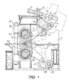
- a crank shear for shearing heavy metal workpieces comprises a housing 1 carrying a pair of blade carriers 2, 3 arranged one above the other.
- Each of the blade carriers is eccentrically mounted on separate shafts and drive means (not shown) serve to rotate the shafts and cause the blade carriers to move towards and away from each other in the well known manner.
- Each blade carrier extends for substantially the entire width of the shear and removably carries a pair of shear blades in supports 4, 5.
- the upper blade carrier 2 has a rigid arm 6 extending outwardly from it and the outer end of the arm is pivotally secured to one end of a link 7.
- a substantially horizontal shaft 8 is mounted for rotation in bearings and an arm 9 is secured to the shaft.
- the outer end of the arm is pivotally secured to the piston rod 10 of a piston-cylinder device 11, the arrangement being such that, when the piston-cylinder device is actuated, the arm 9 is caused to rotate the shaft 8.
- a link 12 which has an end portion pivotally secured to the opposite end of the link 7 from the arm 6.
- the member 12 carries two lugs 13, 14 and the frame 1 carries two rotatable screws 15, 16 respectively.
- the lug 14 is engaged against the lower end of the screw 15 to prevent rotation of the link 12 in a clockwise direction.
- the lug 13 is engaged against the outer end of the screw 16 to prevent further movement of the link 12 in the anti-clockwise direction.
- the link 12 is thus movable by the piston-cylinder device 11 between the two positions in which it engages against one or other of the screws.
- the screws are both adjustable to thereby vary the angular position of movement of the link 12.
- the lower blade carrier 3 has an outwardly extending arm 20, which is connected at one end to a link 21, and the other end of this link is pivotally secured to an arm 22, which is keyed to another substantially horizontal shaft 23.
- This shaft 23 is shown in more detail in Figure 2, where it can be seen that it is mounted for rotation in fixed bearings and an arm 24 is rigidly secured to the shaft and a portion of the arm is pivotally secured to one end of a piston-cylinder device 25.
- the piston-cylinder device By operating the piston-cylinder device, the shaft 23 is rotated and, consequently, the arm 22 is rotated.
- the angular position of the arm 24 is limited by a pair of stops 26, 27 respectively.
- the shear blades in the support 4 are arranged in operative shearing positions and, when the shear is operated, the carriers are displaced towards each other so that these two blades co-operate with each other in a shearing relation on a workpiece 30 positioned between them.
- the piston-cylinder device 11 When these blades need replacing.or, alternatively, if the blades in the support 5 are to be used, the piston-cylinder device 11 is operated to displace the arm 12, pivoting the arm 6 to the position shown in broken lines. This movement of the arm 6 moves the blade in support 5 to the operative shearing position. Similarly, the piston-cylinder device 25 is operated to rotate the shaft 23 and to move the arm 20 into the position shown in broken lines where the blade in support 5 comes into an operative shearing position. In this operative shearing position of the two blades in support 5, the two blades in support 4 are each in a non-operative shearing position.
- the blade carrier 2 and the shaft on which it is mounted are conventionally mounted in a housing 31 which are pivoted about a pivot 33.
- the housing is arranged in its normal operating position and is held in this position by a nut 35 on the upper end of a post 37.
- the nut 35 is removed and the housing 31 is pivoted about the shaft 33 to the position shown in chain line.
- the blades are then in an upward facing position from which they can be lifted upwardly by a crane. Once the blades have been swung to one side, the lower blades can be supported from above and lifted straight up.
Landscapes
- Engineering & Computer Science (AREA)
- Mechanical Engineering (AREA)
- Shearing Machines (AREA)
- Finish Polishing, Edge Sharpening, And Grinding By Specific Grinding Devices (AREA)
Applications Claiming Priority (2)
| Application Number | Priority Date | Filing Date | Title |
|---|---|---|---|
| GB8128428 | 1981-09-21 | ||
| GB8128428 | 1981-09-21 |
Publications (2)
| Publication Number | Publication Date |
|---|---|
| EP0075448A2 true EP0075448A2 (de) | 1983-03-30 |
| EP0075448A3 EP0075448A3 (de) | 1983-06-22 |
Family
ID=10524640
Family Applications (1)
| Application Number | Title | Priority Date | Filing Date |
|---|---|---|---|
| EP82304889A Withdrawn EP0075448A3 (de) | 1981-09-21 | 1982-09-16 | Schermaschine mit doppelten Messern |
Country Status (2)
| Country | Link |
|---|---|
| EP (1) | EP0075448A3 (de) |
| JP (1) | JPS5866614A (de) |
Cited By (5)
| Publication number | Priority date | Publication date | Assignee | Title |
|---|---|---|---|---|
| WO2004054745A1 (de) * | 2002-12-17 | 2004-07-01 | Sms Demag Aktiengesellschaft | Kurbelschere mit zwei messerpaaren zum schneiden von walzband |
| CN103008969A (zh) * | 2012-12-07 | 2013-04-03 | 中冶陕压重工设备有限公司 | 一种大盈量的曲柄剪曲柄头连接块装配相位控制方法 |
| JP2013248704A (ja) * | 2012-05-31 | 2013-12-12 | Nippon Steel & Sumitomo Metal Corp | 切断装置及び切断装置における上刃ホルダの取外し方法 |
| CN107913958A (zh) * | 2017-12-04 | 2018-04-17 | 江苏中天科技股份有限公司 | 一种8字缆吊线切断装置 |
| CN106695600B (zh) * | 2015-07-24 | 2019-02-22 | 北京京诚瑞信长材工程技术有限公司 | 一种曲柄定位装置 |
Family Cites Families (10)
| Publication number | Priority date | Publication date | Assignee | Title |
|---|---|---|---|---|
| US2369253A (en) * | 1943-06-14 | 1945-02-13 | Thomas R Robinson | Clipper for sheet material |
| FR1172973A (fr) * | 1956-03-27 | 1959-02-18 | Schloemann Ag | Procédé pour débiter des éprouvettes dans une matière laminée en mouvement, dans un train de laminoir ou à la suite de celui-ci, et cisaille pour la mise en oeuvre de ce procédé |
| DE1552682C3 (de) * | 1966-08-24 | 1975-08-14 | Schloemann-Siemag Ag, 4000 Duesseldorf | Kurbelschere zum Schneiden von laufendem Walzgut |
| DE1627297A1 (de) * | 1967-06-21 | 1970-11-05 | Erich Thomas | Einrichtung zum schnellen Wechseln von Rundmessern fuer Laengsteilscheren |
| US3513743A (en) * | 1967-08-21 | 1970-05-26 | Nat Steel Corp | Multiple-head slitting apparatus |
| US3606813A (en) * | 1970-07-16 | 1971-09-21 | Hallden Machine Co | Rotary shear |
| US3753381A (en) * | 1971-12-10 | 1973-08-21 | Eickhoff Geb | Web edge control for strip processing lines |
| US3869948A (en) * | 1974-03-07 | 1975-03-11 | Aetna Standard Eng Co | Shear apparatus |
| JPS5367186A (en) * | 1976-11-29 | 1978-06-15 | Hitachi Ltd | Shear |
| SU642097A1 (ru) * | 1976-12-03 | 1979-01-15 | Кировский завод по обработке цветных металлов | Барабанные летучие ножницы |
-
1982
- 1982-09-16 EP EP82304889A patent/EP0075448A3/de not_active Withdrawn
- 1982-09-21 JP JP16595782A patent/JPS5866614A/ja active Pending
Cited By (8)
| Publication number | Priority date | Publication date | Assignee | Title |
|---|---|---|---|---|
| WO2004054745A1 (de) * | 2002-12-17 | 2004-07-01 | Sms Demag Aktiengesellschaft | Kurbelschere mit zwei messerpaaren zum schneiden von walzband |
| RU2328361C2 (ru) * | 2002-12-17 | 2008-07-10 | Смс Демаг Акциенгезелльшафт | Кривошипные ножницы с двумя ножевыми парами для резки катаной полосы |
| CN100503110C (zh) * | 2002-12-17 | 2009-06-24 | Sms迪马格股份公司 | 用于轧制钢带切裁的带有两个刀片副的曲轴剪床 |
| JP2013248704A (ja) * | 2012-05-31 | 2013-12-12 | Nippon Steel & Sumitomo Metal Corp | 切断装置及び切断装置における上刃ホルダの取外し方法 |
| CN103008969A (zh) * | 2012-12-07 | 2013-04-03 | 中冶陕压重工设备有限公司 | 一种大盈量的曲柄剪曲柄头连接块装配相位控制方法 |
| CN106695600B (zh) * | 2015-07-24 | 2019-02-22 | 北京京诚瑞信长材工程技术有限公司 | 一种曲柄定位装置 |
| CN107913958A (zh) * | 2017-12-04 | 2018-04-17 | 江苏中天科技股份有限公司 | 一种8字缆吊线切断装置 |
| CN107913958B (zh) * | 2017-12-04 | 2024-03-29 | 江苏中天科技股份有限公司 | 一种8字缆吊线切断装置 |
Also Published As
| Publication number | Publication date |
|---|---|
| EP0075448A3 (de) | 1983-06-22 |
| JPS5866614A (ja) | 1983-04-20 |
Similar Documents
| Publication | Publication Date | Title |
|---|---|---|
| US4054071A (en) | Flying saw with movable work shifter | |
| EP0386457A1 (de) | Ausrichtbare Biegeeinheit | |
| GB2142863A (en) | Shearing machine | |
| US2254374A (en) | Cutting machine | |
| US2701016A (en) | Rotary flying shear mechanism for rod rolling mills or the like | |
| JPH0255164B2 (de) | ||
| EP0075448A2 (de) | Schermaschine mit doppelten Messern | |
| KR20180128626A (ko) | 다기능 배관 커팅장치 | |
| US4436000A (en) | Sharpening machine for saws | |
| US4218024A (en) | Adjusting device for the cutting blades of a cutting tool | |
| US3222970A (en) | Link mounted saw assembly | |
| US3742801A (en) | Shearing machine | |
| CN113510302B (zh) | 一种复合材料切割装置 | |
| US3603190A (en) | Rotary plate-slitting shear | |
| US4052175A (en) | Automatic snag grinder | |
| US2417556A (en) | Trimming apparatus | |
| CN216175798U (zh) | 一种金属制品加工处理装置 | |
| JPH0811015A (ja) | 鉄筋切断装置 | |
| US2193148A (en) | Shear | |
| US2204904A (en) | Hold-down mechanism | |
| GB1570064A (en) | Bending machine | |
| US3359845A (en) | Sheet metal shears with compensation for knife drum tilt | |
| US2653660A (en) | Portable scrap chopper | |
| CN217104448U (zh) | 一种口罩机用布料裁切装置 | |
| US3737111A (en) | Meat cutter |
Legal Events
| Date | Code | Title | Description |
|---|---|---|---|
| PUAI | Public reference made under article 153(3) epc to a published international application that has entered the european phase |
Free format text: ORIGINAL CODE: 0009012 |
|
| AK | Designated contracting states |
Designated state(s): AT BE CH DE FR GB IT LI LU NL SE |
|
| PUAL | Search report despatched |
Free format text: ORIGINAL CODE: 0009013 |
|
| AK | Designated contracting states |
Designated state(s): AT BE CH DE FR GB IT LI LU NL SE |
|
| STAA | Information on the status of an ep patent application or granted ep patent |
Free format text: STATUS: THE APPLICATION IS DEEMED TO BE WITHDRAWN |
|
| 18D | Application deemed to be withdrawn |
Effective date: 19840223 |
|
| RIN1 | Information on inventor provided before grant (corrected) |
Inventor name: GRONBECH, ROBERT WILLIAM Inventor name: KACZMARYK, EDWARD |