EP0073579A2 - Analyseur automatique du type discret - Google Patents
Analyseur automatique du type discret Download PDFInfo
- Publication number
- EP0073579A2 EP0073579A2 EP82304166A EP82304166A EP0073579A2 EP 0073579 A2 EP0073579 A2 EP 0073579A2 EP 82304166 A EP82304166 A EP 82304166A EP 82304166 A EP82304166 A EP 82304166A EP 0073579 A2 EP0073579 A2 EP 0073579A2
- Authority
- EP
- European Patent Office
- Prior art keywords
- cuvette
- tray
- station
- dispensing
- cuvettes
- Prior art date
- Legal status (The legal status is an assumption and is not a legal conclusion. Google has not performed a legal analysis and makes no representation as to the accuracy of the status listed.)
- Granted
Links
Images

Classifications
-
- G—PHYSICS
- G01—MEASURING; TESTING
- G01N—INVESTIGATING OR ANALYSING MATERIALS BY DETERMINING THEIR CHEMICAL OR PHYSICAL PROPERTIES
- G01N35/00—Automatic analysis not limited to methods or materials provided for in any single one of groups G01N1/00 - G01N33/00; Handling materials therefor
- G01N35/02—Automatic analysis not limited to methods or materials provided for in any single one of groups G01N1/00 - G01N33/00; Handling materials therefor using a plurality of sample containers moved by a conveyor system past one or more treatment or analysis stations
- G01N35/025—Automatic analysis not limited to methods or materials provided for in any single one of groups G01N1/00 - G01N33/00; Handling materials therefor using a plurality of sample containers moved by a conveyor system past one or more treatment or analysis stations having a carousel or turntable for reaction cells or cuvettes
Definitions
- the invention relates to an automated, discrete type, biochemical analytical system.
- Present-day analytical systems may be divided into two categories.
- One such category includes the continuous-flow analytical systems, such as described in the L. Skeggs et al U.S. Patent 3,241,341 and the W. Smythe et al U.S. Patent 3,479,141.
- continuous streams of successive sample segments and reagent are introduced, at properly related flow rates, into the system and passed along an analytical channel, wherein the successive samples are reacted and analyzed in respect of a same analyte.
- the stream of sample segments can be divided, or split, into a number of aliquot streams, which are directed each along individual analytical channels to be reacted and analyzed in respect of a particular analyte.
- the analytical results derived from the analytical channels are thereafter correlated with respect to the patient or source. While such systems as described in the Skeggs et al patent are not selective, in that a fixed battery of analyses is performed, such systems do exhibit an extremely high through-put and are capable of satisfying the test requirements of large clinical laboratories.
- the Smythe et al patent describes a continuous-flow system of high through-put, wherein selectivity is obtained by injecting or introducing, on a selective basis and on in-line fashion, precise volumes of reagents to react with successive sample segments flowing in a continuous stream.
- the second category includes discrete-type analyzers, wherein properly related volumes of sample and reagent are introduced into a reaction cuvette, the resulting reaction product being measured to determine the concentration of the analyte.
- Such systems may be adapted to perform a single type of analysis, termed a batch-type system, or to perform different types of analyses in respect of the individual samples.
- a plurality of reaction cuvettes can be formed into an integral reaction tray, for example as described in our European patent application No. 82303211.5 filed 21st June 1982. Such tray is rotated to advance each cuvette, in turn, between a reagent addition station, a sample addition station, and an analytical or read-out station.
- the first type of reaction can be described as a zero-order rate reaction, as performed in respect of aspartate aminotransferase, alkaline phosphotase, etc., wherein the concentration of the reaction product to be measured varies linearly with time.
- the second type of reaction can be defined as a first-order rate reaction, as performed in respect of urea nitrogen, creatinine, etc., wherein the concentration of the reaction product varies non-linearly with time.
- the third type of reaction can be defined as an end-point reaction, as performed in respect of glucose, total protein, etc., wherein the reaction goes to completion before measurement.
- analyte quantitation in respect of each of such reactions requires that multiple measurements be made, e.g. colorimetrically, of the reaction product. To achieve highly accurate results, therefore, it is essential that such multiple measurements be made in respect of each individual cuvette, whether supported individually or integrally formed in the reaction tray, under identical conditions. Unless this is achieved, accuracy of the analytical result is reduced.
- reaction cuvettes used in discrete-type analytical systems are formed of plastic or glass.
- a beam of light of predetermined wavelength depending upon the analyte to be quantitated, is passed therethrough and along a sight path of controlled length extending through the reaction mixture.
- Any variation in the thickness or quality of any imperfections or residues on the cuvette walls defining the sight path would materially affect the light transmissive properties of the cuvette.
- any misalignment of the individual cuvette during the multiple readings would change the proper relationship of the successive analytical results, or read-outs, with respect to the reference base-line, which is itself determined by a read-out process.
- an analytical system which comprises a cuvette tray comprising a plurality of cuvettes circularly arranged about a rotational axis, at least a first treatment station located with respect to said cuvette tray and at which at least a selected one of said cuvettes is to be repetitively positioned, and means for rotating said cuvette tray about said axis, characterised in that said rotating means is arranged to rotate the cuvette tray bidirectionally about said axis, and means are provided for controlling said rotating means to rotate said cuvette tray in a first direction to locate said selected cuvette at said first station, said controlling means being operative to control said rotating means to rotate said cuvette tray in a second direction prior to rotating said cuvette tray in said first direction to re-position said selected cuvette at said first station.
- a reaction tray comprising a plurality of cuvettes is rotated unidirectionally to successively advance each cuvette, in turn, between different treatment stations, i.e. a reagent-addition station, a sample-addition station, and a read-out station.
- treatment stations i.e. a reagent-addition station, a sample-addition station, and a read-out station.
- the reaction tray effect a full revolution.
- the reaction tray is indexed by a stepping motor coupled via toothed drive belt and a toothed pulley arrangement.
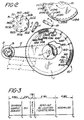
- reaction tray 1 comprising a plurality of reaction cuvettes 3.
- reaction tray 1 is of the type described in our European patent application no. 82303211.5 wherein cuvettes 1 are integrally formed and circularly arranged about the axis of rotation.
- Each cuvette 3 has an open upper end and at least two radially aligned opposing transparent walls 5 and 7.
- Tray 1 is removably mounted and keyed on a vertical shaft 9 supported by bearings 11 and 13.
- Shaft 9 carries a toothed pulley 15, which is engaged by a toothed drive belt 17 driven by toothed drive pulley 19 carried on the shaft of a reversible stepping motor 21.
- Motor 21 is operative to rotate tray 1 in either a clockwise or counterclockwise direction, as indicated by the arrow, through a sequence of angular positions.
- Sample tray 23 disposed adjacent to reaction tray 1 and mounted on the shaft of an AC synchronous motor 25.
- Sample tray 23 comprises a plurality of sample receptacles 27 arranged in circular fashion about the rotational axis of such tray.
- Motor 25 is operative to unidirectionally index sample tray 23, to successively advance receptacles 27, in turn, to a take-off position below an aspirating/dispensing probe 29.
- Probe 29 is adapted, under the control of drive mechanism 30, for vertical reciprocal and for bidirectional rotational movement, as indicated by the arrows, so as to be selectively positioned over and immersed into a receptacle 27 and into a cuvette 3 advanced to sample-dispense station S. Probe 29 operates to aspirate a precise aliquot of the sample contained in such receptacle 27 and to dispense or load the same into such cuvette 3.
- a reagent tray 31 is disposed adjacent to tray 1 and supported on the shaft of an AC synchronous motor 33.
- Reagent tray 31 is adapted to be unidirectionally advanced by motor 33 to selectively position an appropriate reagent below the aspirating/ dispensing probe 37.
- Probe 37 is adapted, under the control of drive mechanism 38, for vertical reciprocal movement and for bidirectional rotational movement, as indicated by the arrows, so as to be selectively positioned over and immersed into reagent container 35 and into a cuvette 3 selectively advanced to reagent- dispense station R.
- Probe 37 operates to aspirate a precise volume of reagent contained in such container 35 and dispense or load the same into such cuvette 3.
- Probes 29 and 37 may be of the aspirating/ dispensing type described in our U.S. Patent 4,121,466. As described, such probe is normally filled with a pilot fluid which is immiscible with the aqueous liquid, i.e. sample or reagent, to be aspirated and dispensed. Also, an immiscible liquid is flowed downwardly, at a controlled rate, over the outer probe surface, to coat and prevent contact of such surface with the liquid to be aspirated. Accordingly, contamination is positively avoided between the successive liquids, whether sample or reagent, into which the probe is immersed. During the actual aspiration and dispense cycles, the flow of immiscible liquid over the probe surface may be discontinued. The operation of probes 29 and 37 are hereafter more particularly described.
- the contents of cuvettes 3 are colorimetrically analyzed, in turn, at read-out station RO, to quantitate the particular analyte for which the contained sample has been reacted.
- Station RO comprises a light source 39 and collimating lens 41 for directing a beam of light through walls 5 and 7 of cuvette 3 positioned thereat.
- a detector 43 is located to receive the emerging light beam and generates an electrical signal indicative of the color depth, or analyte concentration, of the reacted sample disposed between windows 5 and 7.
- a multi-filter wheel 45 is interposed between collimating lens 41 and wall 5 of positioned cuvette 3, which determines the wavelength of the light beam.
- a particular analyte is normally absorptive of light of a particular wavelength, the degree of absorption being indicative of the analyte concentration in the reacted sample.
- the output signal of detector 43 is directed to a register 47, which is adapted to store said signals, on an individual sample basis.
- controller 49 which is inputted by an operator to identify, as to source patient, each sample loaded in sample tray 23 and, also, to indicate the particular analysis to be effected of each such sample. According to such inputs, controller 49 implements a number of sub-routines for controlling the various components of the system to selectively analyze each such sample, as hereafter described.
- tray 1 comprises one-hundred cuvettes 3
- forty indexing positions of tray 1 are defined between station R and station RO
- three indexing positions of tray are defined between station R and station S.
- cuvettes 3 (1) through 3 (35) of Figure 2 have had both reagent and sample dispensed therein and, also, cuvettes 3 (36) through 3 (39) have had reagent dispensed therein preparatory to the dispensing thereof of sample contained in receptacles 27 (36) through 27 (39), respectively, at station S.
- controller 49 operates under appropriate sub-routines to operate motor 33 to locate at station R an appropriate receptacle 35, e.g. receptacle 35 (4), containing the appropriate reagent to react sample contained in sample receptacle 27 (40); to operate motor 25 to advance the next receptacle 27 (37) containing the sample to be reacted in the reagent-loaded cuvette 3 (37) at station S and into which an appropriate reagent has been previously dispensed; and to operate stepping motor 21 to advance cuvettes 3 (37) over 3 (40) to stations S and R, respectively.
- an appropriate receptacle 35 e.g. receptacle 35 (4), containing the appropriate reagent to react sample contained in sample receptacle 27 (40)
- controller 25 operates under appropriate sub-routines to operate motor 33 to locate at station R an appropriate receptacle 35, e.g. receptacle 35 (4), containing the appropriate reagent to react sample contained in sample recept
- controller 49 operates drive mechanisms 30 and 38 to concurrently control probes 29 and 37, respectively, to aspirate appropriate volumes of sample and reagent, respectively, from receptacles 27 (37) and 35 (4) and to dispense the same into cuvettes 3 (37) and 3 (40) positioned at stations R and S, respectively.
- Such dispensing operation occurs during time interval to-t 1 of Figure 3, which may be of three-second duration.
- controller 49 operates stepping motor 21 to advance tray 1 in short, rapid incremental steps, to mix the contents of each "loaded" cuvette 3 during time interval t l -t 3 , which have a two-second duration.
- tray 1 may be advanced or indexed, say, twenty-eight angular positions, with a momentary abrupt stop at each position. Such mixing is effected in incremental steps shorter and, also, at a rate faster than the normal indexing of tray 1.
- the contents of all "loaded" cuvettes 3 are sufficiently agitated to ensure thorough mixing of their contents.
- controller 49 reverses stepping motor 21 to normalize tray 1 by returning cuvette 3 (36) and 3 (40) to stations S and R, respectively, and to reposition cuvette 3 (1) at station RO. Normalization of tray 1 is effected during time interval t 2 -t 3 , which may have a one-second duration.
- controller 49 operates stepping motor 21 to normally index tray 1 in a clockwise direction, to advance cuvettes 3 (1) through 3 (40), in turn, to station R0.
- Synchronously controller 49 operates wheel 45 to selectively position an appropriate filter to pass light an appropriate wavelength through each of the cuvettes 3 (1) through 3 (36), in turn, to effect a particular analyte analysis.
- the output of detector 43 in respect of each such cuvette is stored as the base line for the subsequent quantitation of a particular analyte to be subsequently analyzed in such cuvettes.
- tray 1 may be indexed one position each .125 second, such that cuvettes 3 (1) through 3 (40) are read out during time interval t 2 -t 4 , which may have a five-second duration.
- cuvette 3 (40) When the read-out cycle has been completed at time t 4 , cuvette 3 (40) is located at station RO and the contents of each of cuvettes 3 (1) through 3 (40) have been successively analyzed and the analytical results appropriately stored in register 47.
- controller 49 operates stepping motor 21 to rotate tray 1 in a counterclockwise direction, to normalize the system preparatory to a next dispensing cycle.
- the reverse indexing of tray 1 duplicates the forward indexing of tray 1, except for being effected in a reverse direction.
- tray 1 is reverse indexed to one angular position less than it had been forward-indexed. It should be appreciated, however, that tray 1 can be reverse indexed to any number of angular positions, depending upon the particular requirements of the system.
- controller 49 commences a next operating cycle by operating motor 25 to advance the next receptacle 27 (38) to station S and motor 33 to advance, for example, receptacle 35 (1) to station R. Thereupon, controller 49 operates drive mechanisms 30 and 38 to control probes 29 and 37, respectively, to aspirate and dispense appropriate volumes of sample from receptacle 27 (38) and reagent from receptacle 35 (1) into cuvettes 3 (38) and 3 (41), respectively, located at stations S and R, respectively. As mentioned above, reagent dispensed into cuvette 3 (41) is intended for reaction with the sample contained in receptacle 27 (41), which will be dispensed into cuvette 3 (41) when advanced to station S.
- controller 49 Upon completion of the aspirate/dispense cycle, at time t 21 controller 49 operates stepping motor 21 to effect a next mixing cycle, as described above, to agitate and mix the contents of all "loaded" cuvettes 3 in tray 1 and to subsequently normalize tray 1, at time interval t 31 to reposition cuvettes 3 (41), 3 (37), and 3 (2) at stations R, S and RO, respectively. Thereafter, stepping motor 21 is operated by controller 49 to advance each cuvette 3 (2) through 3 (41), in turn, through station RO, whereat the contents of such cuvettes are analyzed, in turn, and the analytical results, i.e., the output of detector 43, are stored in register 47 in respect of the corresponding source patients, as described above.
- controller 49 When cuvette 3 (41) is located at station RO, controller 49 operates motor 21 to rotate tray 1 in a counterclockwise direction. Tray 1 is reverse indexed through thirty-nine angular positions, to locate cuvette 3 (3) at station RO, cuvette 3 (42) at station R and cuvette 3 (39) at-station S, preparatory to a next operational cycle.
- each cuvette at station R0 As successive readouts are required to calculate analyte concentration and to ensure accurate analytical results, the successive positionings of each cuvette at station R0, at least, must be exactly duplicated. Such exact repositioning ensures that variations in the light transmission properties due to transmission or geometric non-uniformities of the walls 5 and 7 of each cuvette 3 are cancelled out for each successive measurement, that is, such variations are constant for each measurement. Exact repositioning is achieved by rotating tray 1 a reverse direction, so as to normalize the system, whereby the relationship of belt 17 and drive pulleys 15 and 19 is fixed and invariable in respect to the positioning of each individual cuvette 3 at a treatment station, say, R0. A same length of belt 17 is used in successively positioning each cuvette 3 at station RO.
- such cuvette is indexed during the read-out cycle, at time t 3 -t 4 , through forty angular positions by passage of a section L of belt 17 over drive pulley 19, as indicated in Figure 3.
- the passage of section L', of belt 17 over drive pulley 19 equivalent to thirty-nine angular positions is effective to position cuvette 3 (39) at station RO.
- section L' of belt 17 is returned over drive pulley 19 to locate cuvette 3 (41) at station R, cuvette 3 (40) having been normalized to one angular position beyond station R.
- a section L' of belt 17, including section L' and equivalent to forty angular positions of tray 1, is passed over drive pulley 19 to advance cuvette 3 (41) to station RO.
- the passage of section L' of belt 17 over drive pulley 19, at this time, is effective to advance cuvette 3 (40) through thirty-nine angular positions to be exactly repositioned at station RO. Any dimensional errors in those portions of belt 17 actually engaging pulleys 15 and 19 or either of the pulleys will affect the positioning of cuvette 3 (39) at station RO.
- any tooth-to-tooth dimensional error should exist in any portion of belt 17 or in any portion of either of the pulleys 15 and 19, a positioning error is introduced only when such portion of belt 17 engages either of pulleys 15 or 19 or when such portion of the pulley is engaged by belt 17 and would affect only the initial alignment or positioning of a particular cuvette at a treatment station, say, RO.
- a same positioning error is re-introduced during each successive repositioning of such cuvette at a treatment station, whereby the position of such cuvette is exactly duplicated.
- a repositioning of a cuvette at a particular station requires a complete revolution of tray 1 and, unless the drive belt, such as 17, is exactly equal to that length required to rotate tray 1 through one revolution, the relationship of the drive belt to the driving pulleys is not fixed and invariable with respect to each cuvette and any tooth-to-tooth dimensional errors would be cumulative, whereby an exact repositioning of each such cuvette at a particular treatment station could not be duplicated.
Applications Claiming Priority (2)
| Application Number | Priority Date | Filing Date | Title |
|---|---|---|---|
| US29676081A | 1981-08-27 | 1981-08-27 | |
| US296760 | 1981-08-27 |
Publications (3)
| Publication Number | Publication Date |
|---|---|
| EP0073579A2 true EP0073579A2 (fr) | 1983-03-09 |
| EP0073579A3 EP0073579A3 (en) | 1983-08-24 |
| EP0073579B1 EP0073579B1 (fr) | 1987-12-02 |
Family
ID=23143431
Family Applications (1)
| Application Number | Title | Priority Date | Filing Date |
|---|---|---|---|
| EP82304166A Expired EP0073579B1 (fr) | 1981-08-27 | 1982-08-06 | Analyseur automatique du type discret |
Country Status (5)
| Country | Link |
|---|---|
| EP (1) | EP0073579B1 (fr) |
| JP (1) | JPS5835465A (fr) |
| AU (1) | AU563145B2 (fr) |
| CA (1) | CA1199859A (fr) |
| DE (1) | DE3277784D1 (fr) |
Cited By (5)
| Publication number | Priority date | Publication date | Assignee | Title |
|---|---|---|---|---|
| EP0216026A1 (fr) * | 1985-06-26 | 1987-04-01 | Japan Tectron Instruments Corporation | Appareil pour l'analyse automatique |
| EP0222466A2 (fr) * | 1985-10-31 | 1987-05-20 | Bio/Data Corporation | Procédé et dispositif d'analyse automatique d'échantillons individuels de fluides |
| GB2186080A (en) * | 1986-01-21 | 1987-08-05 | Imp Tobacco Co Ltd | Chemical analysis system |
| EP0356569A1 (fr) * | 1988-09-02 | 1990-03-07 | Eppendorf-Netheler-Hinz Gmbh | Méthode d'analyse d'échantillons liquides dans des cuvettes et appareil d'analyse pour la mise en oeuvre de ladite méthode |
| AU2004238846B2 (en) * | 2003-05-09 | 2007-10-25 | Caliper Life Sciences, Inc. | Automated sample analysis |
Families Citing this family (5)
| Publication number | Priority date | Publication date | Assignee | Title |
|---|---|---|---|---|
| JPS60138923U (ja) * | 1984-02-27 | 1985-09-13 | ナショナル住宅産業株式会社 | 外壁パネル |
| JPH06100608B2 (ja) * | 1984-03-08 | 1994-12-12 | 株式会社日立製作所 | 自動分析装置 |
| JPS61274265A (ja) * | 1985-05-30 | 1986-12-04 | Nippon Tectron Co Ltd | 自動分析装置 |
| JPH0431371Y2 (fr) * | 1986-11-26 | 1992-07-28 | ||
| US7250303B2 (en) | 2001-07-20 | 2007-07-31 | Ortho-Clinical Diagnostics, Inc. | Chemistry system for a clinical analyzer |
Citations (2)
| Publication number | Priority date | Publication date | Assignee | Title |
|---|---|---|---|---|
| US3978992A (en) * | 1975-07-02 | 1976-09-07 | International Business Machines Corporation | Positioning apparatus |
| US4276258A (en) * | 1980-01-28 | 1981-06-30 | Coulter Electronics, Inc. | Sample and stat feeding system and sample tray |
Family Cites Families (3)
| Publication number | Priority date | Publication date | Assignee | Title |
|---|---|---|---|---|
| GB1509186A (en) * | 1974-05-08 | 1978-05-04 | Secr Social Service Brit | Specimen agitation apparatus |
| JPS5936227B2 (ja) * | 1975-09-26 | 1984-09-03 | 株式会社日立製作所 | 化学分析方法 |
| JPS57156543A (en) * | 1981-03-24 | 1982-09-27 | Olympus Optical Co Ltd | Device for chemical analysis |
-
1982
- 1982-04-15 CA CA000401076A patent/CA1199859A/fr not_active Expired
- 1982-05-25 AU AU84143/82A patent/AU563145B2/en not_active Ceased
- 1982-07-20 JP JP12523382A patent/JPS5835465A/ja active Granted
- 1982-08-06 EP EP82304166A patent/EP0073579B1/fr not_active Expired
- 1982-08-06 DE DE8282304166T patent/DE3277784D1/de not_active Expired
Patent Citations (2)
| Publication number | Priority date | Publication date | Assignee | Title |
|---|---|---|---|---|
| US3978992A (en) * | 1975-07-02 | 1976-09-07 | International Business Machines Corporation | Positioning apparatus |
| US4276258A (en) * | 1980-01-28 | 1981-06-30 | Coulter Electronics, Inc. | Sample and stat feeding system and sample tray |
Cited By (6)
| Publication number | Priority date | Publication date | Assignee | Title |
|---|---|---|---|---|
| EP0216026A1 (fr) * | 1985-06-26 | 1987-04-01 | Japan Tectron Instruments Corporation | Appareil pour l'analyse automatique |
| EP0222466A2 (fr) * | 1985-10-31 | 1987-05-20 | Bio/Data Corporation | Procédé et dispositif d'analyse automatique d'échantillons individuels de fluides |
| EP0222466A3 (fr) * | 1985-10-31 | 1988-07-06 | Bio/Data Corporation | Procédé et dispositif d'analyse automatique d'échantillons individuels de fluides |
| GB2186080A (en) * | 1986-01-21 | 1987-08-05 | Imp Tobacco Co Ltd | Chemical analysis system |
| EP0356569A1 (fr) * | 1988-09-02 | 1990-03-07 | Eppendorf-Netheler-Hinz Gmbh | Méthode d'analyse d'échantillons liquides dans des cuvettes et appareil d'analyse pour la mise en oeuvre de ladite méthode |
| AU2004238846B2 (en) * | 2003-05-09 | 2007-10-25 | Caliper Life Sciences, Inc. | Automated sample analysis |
Also Published As
| Publication number | Publication date |
|---|---|
| EP0073579B1 (fr) | 1987-12-02 |
| EP0073579A3 (en) | 1983-08-24 |
| DE3277784D1 (en) | 1988-01-14 |
| JPS5835465A (ja) | 1983-03-02 |
| AU8414382A (en) | 1983-03-03 |
| AU563145B2 (en) | 1987-07-02 |
| CA1199859A (fr) | 1986-01-28 |
| JPH0321062B2 (fr) | 1991-03-20 |
Similar Documents
| Publication | Publication Date | Title |
|---|---|---|
| US4629703A (en) | Automated analytical system | |
| EP1465728B1 (fr) | Ensemble de recipients empilables d'aliquotes | |
| US4338279A (en) | Automatic analyzing apparatus | |
| EP1325343B1 (fr) | Accroissement de debit dans un analyseur clinique automatique par la separation d'analyses selon le type | |
| US4298570A (en) | Tray section for automated sample handling apparatus | |
| US5773662A (en) | Automatic analyzing method using a plurality of reagents and apparatus therefor | |
| EP0109278B1 (fr) | Système à écoulement continu à conduite unique | |
| EP0073579B1 (fr) | Analyseur automatique du type discret | |
| US7338803B2 (en) | Method for increasing capacity in an automatic clinical analyzer by using modular reagent delivery means | |
| US20030040117A1 (en) | Increasing throughput in an automatic clinical analyzer by partitioning assays according to type | |
| JPS6244663A (ja) | 多項目自動分析装置 | |
| JPH0347465B2 (fr) | ||
| JPH047956B2 (fr) | ||
| US3773423A (en) | Automatic analyzer | |
| JPH06249860A (ja) | 自動分析装置 | |
| JP2001194371A (ja) | 化学分析装置 | |
| JP3377270B2 (ja) | 自動化学分析装置 | |
| JP2508115B2 (ja) | 自動生化学分析装置 | |
| JPH0684973B2 (ja) | 自動分析装置 | |
| CA1199258A (fr) | Systeme d'analyse automatise | |
| JPH06100608B2 (ja) | 自動分析装置 | |
| JPH02284063A (ja) | 自動分析装置 | |
| Schwartz | Continuous flow analysis | |
| JPS6361959A (ja) | 自動分析装置 | |
| JPH0472186B2 (fr) |
Legal Events
| Date | Code | Title | Description |
|---|---|---|---|
| PUAI | Public reference made under article 153(3) epc to a published international application that has entered the european phase |
Free format text: ORIGINAL CODE: 0009012 |
|
| AK | Designated contracting states |
Designated state(s): BE CH DE FR GB IT LI NL SE |
|
| PUAL | Search report despatched |
Free format text: ORIGINAL CODE: 0009013 |
|
| AK | Designated contracting states |
Designated state(s): BE CH DE FR GB IT LI NL SE |
|
| 17P | Request for examination filed |
Effective date: 19840111 |
|
| GRAA | (expected) grant |
Free format text: ORIGINAL CODE: 0009210 |
|
| AK | Designated contracting states |
Kind code of ref document: B1 Designated state(s): BE CH DE FR GB IT LI NL SE |
|
| ITF | It: translation for a ep patent filed |
Owner name: JACOBACCI & PERANI S.P.A. |
|
| REF | Corresponds to: |
Ref document number: 3277784 Country of ref document: DE Date of ref document: 19880114 |
|
| ET | Fr: translation filed | ||
| PLBE | No opposition filed within time limit |
Free format text: ORIGINAL CODE: 0009261 |
|
| STAA | Information on the status of an ep patent application or granted ep patent |
Free format text: STATUS: NO OPPOSITION FILED WITHIN TIME LIMIT |
|
| 26N | No opposition filed | ||
| REG | Reference to a national code |
Ref country code: CH Ref legal event code: PUE Owner name: TECHNICON INSTRUMENTS CORPORATION TRANSFER- TECHNI |
|
| ITPR | It: changes in ownership of a european patent |
Owner name: FUSIONI;REVGROUP PANTRY MIRROR CORP. |
|
| REG | Reference to a national code |
Ref country code: GB Ref legal event code: 732 |
|
| REG | Reference to a national code |
Ref country code: FR Ref legal event code: TP |
|
| NLS | Nl: assignments of ep-patents |
Owner name: TECHNICON INSTRUMENTS CORPORATION (A DELAWARE CORP |
|
| NLS | Nl: assignments of ep-patents |
Owner name: TECHNICON INSTRUMENTS CORPORATION (A DELAWARE CORP |
|
| ITTA | It: last paid annual fee | ||
| PGFP | Annual fee paid to national office [announced via postgrant information from national office to epo] |
Ref country code: CH Payment date: 19930623 Year of fee payment: 12 |
|
| PGFP | Annual fee paid to national office [announced via postgrant information from national office to epo] |
Ref country code: SE Payment date: 19930722 Year of fee payment: 12 |
|
| PGFP | Annual fee paid to national office [announced via postgrant information from national office to epo] |
Ref country code: NL Payment date: 19930831 Year of fee payment: 12 |
|
| PGFP | Annual fee paid to national office [announced via postgrant information from national office to epo] |
Ref country code: BE Payment date: 19930916 Year of fee payment: 12 |
|
| PG25 | Lapsed in a contracting state [announced via postgrant information from national office to epo] |
Ref country code: SE Effective date: 19940807 |
|
| PG25 | Lapsed in a contracting state [announced via postgrant information from national office to epo] |
Ref country code: LI Effective date: 19940831 Ref country code: CH Effective date: 19940831 Ref country code: BE Effective date: 19940831 |
|
| EAL | Se: european patent in force in sweden |
Ref document number: 82304166.0 |
|
| BERE | Be: lapsed |
Owner name: TECHNICON INSTRUMENTS CORP. Effective date: 19940831 |
|
| PG25 | Lapsed in a contracting state [announced via postgrant information from national office to epo] |
Ref country code: NL Effective date: 19950301 |
|
| NLV4 | Nl: lapsed or anulled due to non-payment of the annual fee | ||
| REG | Reference to a national code |
Ref country code: CH Ref legal event code: PL |
|
| EUG | Se: european patent has lapsed |
Ref document number: 82304166.0 |
|
| PGFP | Annual fee paid to national office [announced via postgrant information from national office to epo] |
Ref country code: FR Payment date: 19990719 Year of fee payment: 18 |
|
| PGFP | Annual fee paid to national office [announced via postgrant information from national office to epo] |
Ref country code: GB Payment date: 19990721 Year of fee payment: 18 |
|
| PGFP | Annual fee paid to national office [announced via postgrant information from national office to epo] |
Ref country code: DE Payment date: 20000308 Year of fee payment: 18 |
|
| PG25 | Lapsed in a contracting state [announced via postgrant information from national office to epo] |
Ref country code: GB Free format text: LAPSE BECAUSE OF NON-PAYMENT OF DUE FEES Effective date: 20000806 |
|
| GBPC | Gb: european patent ceased through non-payment of renewal fee |
Effective date: 20000806 |
|
| PG25 | Lapsed in a contracting state [announced via postgrant information from national office to epo] |
Ref country code: FR Free format text: LAPSE BECAUSE OF NON-PAYMENT OF DUE FEES Effective date: 20010430 |
|
| PG25 | Lapsed in a contracting state [announced via postgrant information from national office to epo] |
Ref country code: DE Free format text: LAPSE BECAUSE OF NON-PAYMENT OF DUE FEES Effective date: 20010501 |
|
| REG | Reference to a national code |
Ref country code: FR Ref legal event code: ST |