EP0073519B1 - Optical disc player - Google Patents
Optical disc player Download PDFInfo
- Publication number
- EP0073519B1 EP0073519B1 EP82108012A EP82108012A EP0073519B1 EP 0073519 B1 EP0073519 B1 EP 0073519B1 EP 82108012 A EP82108012 A EP 82108012A EP 82108012 A EP82108012 A EP 82108012A EP 0073519 B1 EP0073519 B1 EP 0073519B1
- Authority
- EP
- European Patent Office
- Prior art keywords
- error
- detecting
- optical disc
- condition
- signal
- Prior art date
- Legal status (The legal status is an assumption and is not a legal conclusion. Google has not performed a legal analysis and makes no representation as to the accuracy of the status listed.)
- Expired
Links
Images
Classifications
-
- G—PHYSICS
- G11—INFORMATION STORAGE
- G11B—INFORMATION STORAGE BASED ON RELATIVE MOVEMENT BETWEEN RECORD CARRIER AND TRANSDUCER
- G11B7/00—Recording or reproducing by optical means, e.g. recording using a thermal beam of optical radiation by modifying optical properties or the physical structure, reproducing using an optical beam at lower power by sensing optical properties; Record carriers therefor
- G11B7/004—Recording, reproducing or erasing methods; Read, write or erase circuits therefor
- G11B7/005—Reproducing
-
- G—PHYSICS
- G11—INFORMATION STORAGE
- G11B—INFORMATION STORAGE BASED ON RELATIVE MOVEMENT BETWEEN RECORD CARRIER AND TRANSDUCER
- G11B20/00—Signal processing not specific to the method of recording or reproducing; Circuits therefor
- G11B20/10—Digital recording or reproducing
- G11B20/14—Digital recording or reproducing using self-clocking codes
-
- G—PHYSICS
- G11—INFORMATION STORAGE
- G11B—INFORMATION STORAGE BASED ON RELATIVE MOVEMENT BETWEEN RECORD CARRIER AND TRANSDUCER
- G11B20/00—Signal processing not specific to the method of recording or reproducing; Circuits therefor
- G11B20/10—Digital recording or reproducing
- G11B20/18—Error detection or correction; Testing, e.g. of drop-outs
- G11B20/1876—Interpolating methods
-
- G—PHYSICS
- G11—INFORMATION STORAGE
- G11B—INFORMATION STORAGE BASED ON RELATIVE MOVEMENT BETWEEN RECORD CARRIER AND TRANSDUCER
- G11B27/00—Editing; Indexing; Addressing; Timing or synchronising; Monitoring; Measuring tape travel
- G11B27/10—Indexing; Addressing; Timing or synchronising; Measuring tape travel
- G11B27/34—Indicating arrangements
-
- G—PHYSICS
- G11—INFORMATION STORAGE
- G11B—INFORMATION STORAGE BASED ON RELATIVE MOVEMENT BETWEEN RECORD CARRIER AND TRANSDUCER
- G11B27/00—Editing; Indexing; Addressing; Timing or synchronising; Monitoring; Measuring tape travel
- G11B27/36—Monitoring, i.e. supervising the progress of recording or reproducing
Definitions
- This invention relates to an optical disc player as defined in the preamble of claim 1.
- Such a disc player is known from Journal of the Audio Engineering Society Vol. 29, No 1-2, 1981, p. 58-66.
- the disc In an optical disc player which reproduces information data such as video signals, digital audio signals and so on from an optical disc by laser beam scanning, the disc is provided with a protective layer on the surface forming the information signal as pits or bumps. Since scanning laser beam is brought into focus on the information surface, relatively small dust particles, defects or scars on the protective layer are out of focus of the laser beam so as not to influence the reproduced signals.
- an object (the aim) of this invention is to provide an optical disc player which can be simply constructed and which gives an indication in respect to obstructions such as dust or scars on the surface of the disc.
- the invention is also based on the use of an error correcting code as described in the beforementioned article, to indicate the obstructions on the disc.
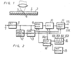
- an optical disc 1 with a previously recorded information signal which by way of example may be a digital signal including an error correcting code, has an information layer 2 constructed of a reflector and a protective layer 3 formed of transparent resin or the like and laminated on the information layer 2.
- the surface of the information layer 2 is scanned by a laser beam 4, for instance, and from the reflected beam a reproduction signal is obtained.
- a dust particle 5 or scars 6 are present on the surface of the protective layer 3, the reproduced signal is not influenced by such dust particles 5 or scars 6, if relatively small since the laser beam is out of focus in the plane of the outer surface of the protective layer 3. Nevertheless when the dust particles 5 or scars 6 are large enough to influence or obstruct larger areas across the path of the laser beam 4, the reproduced signal is seriously distorted or damaged.
- An electric signal which is converted from an optical signal reproduced from the optical disc 1 by an optical pickup device (not shown), is supplied to an input terminal 7.
- the input signal is a digital information signal containing an error detecting and error correcting code for example a Cyclic Redundancy Code (CRCC) or a Reed-Solomon Code, which is described in the beforementioned article.
- the digital signal from the input 7 is supplied to a bit detection circuit 8 which includes a wave form shaping circuit and produces a bit information signal.
- the output signal from the bit detection circuit 8 is provided to a demodulation block 9 which converts the bit information signal to an original binary data signal to be supplied to an error detecting and error correcting circuit 10.
- the error detecting and error correcting circuit 10 operates the binary data by the error detecting and error correcting code in one error correcting block so as to produce the corrected data or the uncorrected data with an error pointer bit indicating that a respective part of the data is bad and a 2 bit condition flag data indicating the result of correcting operation in the error correcting block as follows:
- the corrected or interpolated data if the data was uncorrected is supplied to an output circuit 11 which inludes, in case that the data is a PCM stereo audio signal, a left and right signal separating circuit, a pair of digital to analogue converting circuits and a pair of low pass filters being connected to left and right output terminals 11 Land 11 R, respectively.
- the output signal from the bit detection circuit 8 is also supplied to a clock signal reproducing circuit 12 and a synchronizing signal separating circuit 13.
- the clock signal reproducing circuit 12 extracts a bit clock signal from the reproduced bit information signal which is supplied to the synchronizing signal separating circuit 13, in which various timing signals such as synchronizing signal are generated.
- the various timing signals are supplied to the demodulation block 9, to the error detecting and error correcting circuit 10 and to output circuit 11 as a timing signal, respectively.
- a system control circuit 14 generates control signals corresponding to various functions for example, PLAY, STOP, VOLUME CONTROL and so on, selected by a mode selector 15 so as to control various circuits by the control signals through a bus line 14a.
- the error pointer bit orthe 2- bit condition flag data from the error detecting and error correcting circuit 10 is supplied through the system control circuit 14 to a display equipment 16 which indicates a condition of obstruction at the laser beam scanning area such as dust 5 or scar 6.
- the display equipment 16 has four light emitting devices 16A, 16B, 16C and 16D.
- the other parts are constructed similar as with a conventional optical disc player of this type.
- the condition or size of the obstructions like the dust particles 5 or scars 6 on the optical disc 1 are indicated by means of the error correcting condition flag data.
- the light emitting device 16D ofthe display 16 is turned on dueto stain like dust, it is an indication to the user of the disc player to clean the surface of the disc 1, e.g. with alcohol.
- the error pointer bit indicating bad or good is also employed as error condition information.
Landscapes
- Engineering & Computer Science (AREA)
- Signal Processing (AREA)
- Optical Recording Or Reproduction (AREA)
- Investigating Or Analysing Materials By Optical Means (AREA)
- Holo Graphy (AREA)
- Optical Record Carriers And Manufacture Thereof (AREA)
Priority Applications (1)
| Application Number | Priority Date | Filing Date | Title |
|---|---|---|---|
| AT82108012T ATE38446T1 (de) | 1981-08-31 | 1982-08-31 | Optischer plattenspieler. |
Applications Claiming Priority (2)
| Application Number | Priority Date | Filing Date | Title |
|---|---|---|---|
| JP136844/81 | 1981-08-31 | ||
| JP56136844A JPS5837847A (ja) | 1981-08-31 | 1981-08-31 | 光学式デイスク再生装置 |
Publications (3)
| Publication Number | Publication Date |
|---|---|
| EP0073519A2 EP0073519A2 (en) | 1983-03-09 |
| EP0073519A3 EP0073519A3 (en) | 1984-08-22 |
| EP0073519B1 true EP0073519B1 (en) | 1988-11-02 |
Family
ID=15184820
Family Applications (1)
| Application Number | Title | Priority Date | Filing Date |
|---|---|---|---|
| EP82108012A Expired EP0073519B1 (en) | 1981-08-31 | 1982-08-31 | Optical disc player |
Country Status (8)
| Country | Link |
|---|---|
| US (1) | US4519058A (enExample) |
| EP (1) | EP0073519B1 (enExample) |
| JP (1) | JPS5837847A (enExample) |
| KR (1) | KR840001363A (enExample) |
| AT (1) | ATE38446T1 (enExample) |
| AU (1) | AU558622B2 (enExample) |
| CA (1) | CA1192306A (enExample) |
| DE (1) | DE3279191D1 (enExample) |
Families Citing this family (18)
| Publication number | Priority date | Publication date | Assignee | Title |
|---|---|---|---|---|
| JPS59165207A (ja) * | 1983-03-11 | 1984-09-18 | Hitachi Ltd | 情報記録方式 |
| NL8303061A (nl) * | 1983-09-02 | 1985-04-01 | Philips Nv | Inrichting voor het uitlezen van een optisch uitleesbare registratiedrager. |
| NL8303562A (nl) * | 1983-10-17 | 1985-05-17 | Philips Nv | Inrichting voor het weergeven van informatie van een optisch uitleesbare registratiedrager. |
| DE3341628A1 (de) * | 1983-11-17 | 1985-05-30 | Polygram Gmbh, 2000 Hamburg | Geraeteanordnung zur fehlerermittlung bei plattenfoermigen informationstraegern |
| JPS60161428U (ja) * | 1983-11-30 | 1985-10-26 | 日本エアー・フイルター株式会社 | フイルタ−組立体 |
| US5247505A (en) * | 1985-04-17 | 1993-09-21 | Canon Kabushiki Kaisha | Information recording method for reciprocally recording and verifying information |
| JPH0756734B2 (ja) * | 1985-05-27 | 1995-06-14 | 松下電器産業株式会社 | 情報記録再生装置 |
| CA1320268C (en) * | 1986-09-10 | 1993-07-13 | Wataru Sakagami | Information record medium having an area for recording information indicating logical erasure of data and method for recording information on the same |
| JPH0770173B2 (ja) * | 1987-03-06 | 1995-07-31 | 松下電器産業株式会社 | 情報記録再生装置 |
| WO1992022064A1 (de) * | 1991-06-07 | 1992-12-10 | Deutsche Thomson-Brandt Gmbh | Fehlerartsignalisation optischer informationsträger |
| US5485444A (en) * | 1991-06-07 | 1996-01-16 | Deustsche Thomson-Brandt Gmbh | Signalization of types of defects of an optical information carrier |
| NL9200397A (nl) * | 1992-03-04 | 1993-10-01 | Philips Nv | Informatie-optekeninrichting. |
| US5812506A (en) * | 1992-04-10 | 1998-09-22 | Wea Manufacturing, Inc. | System and methods for measuring and correcting for overshoot in a high frequency (HF) signal generated by a compact disc player during testing of a compact disc |
| JP3336581B2 (ja) * | 1992-10-19 | 2002-10-21 | 富士写真フイルム株式会社 | 追記型光ディスクの媒体検査方法およびシステム |
| DE69427685T2 (de) * | 1993-09-29 | 2002-04-25 | Sony Corp., Tokio/Tokyo | Verfahren und vorrichtung zur datenwiedergabe |
| EP1816645A1 (en) | 2006-02-02 | 2007-08-08 | Thomson Licensing S.A. | Method for controlling the quality of storage media |
| CN101449329B (zh) * | 2006-05-15 | 2011-06-08 | 皇家飞利浦电子股份有限公司 | 光盘读取设备及其方法 |
| US7791994B2 (en) * | 2008-05-29 | 2010-09-07 | Mediatek Inc. | Apparatus and method for demodulating input signal modulated from reference signal and data signal |
Family Cites Families (6)
| Publication number | Priority date | Publication date | Assignee | Title |
|---|---|---|---|---|
| US3585619A (en) * | 1969-01-14 | 1971-06-15 | Mohawk Data Sciences Corp | Magnetic tape readout system with means to generate artificial signals |
| DE2326898A1 (de) * | 1973-05-25 | 1974-12-12 | Polygram Gmbh | Verfahren und schaltungsanordnung zur ermittlung und kompensation von stoerungen bei der optoelektrischen wiedergabe von auf einem plattenfoermigen informationstraeger aufgezeichneten audio- und/oder videosignalen |
| US4145758A (en) * | 1977-10-25 | 1979-03-20 | Drexler Technology Corporation | Error checking method and apparatus for digital data in optical recording systems |
| DE2851822C2 (de) * | 1978-11-30 | 1986-01-16 | Polygram Gmbh, 2000 Hamburg | Verfahren zur Fehlerbewertung bei auf rotierenden Informationsträgern in Spiralspuren eingespeicherten Signalen und Schaltungsanordnung zur Durchführung des Verfahrens |
| US4308557A (en) * | 1979-10-12 | 1981-12-29 | Rca Corporation | Video disc system |
| US4309721A (en) * | 1979-10-12 | 1982-01-05 | Rca Corporation | Error coding for video disc system |
-
1981
- 1981-08-31 JP JP56136844A patent/JPS5837847A/ja active Granted
-
1982
- 1982-08-24 CA CA000410037A patent/CA1192306A/en not_active Expired
- 1982-08-25 KR KR1019820003827A patent/KR840001363A/ko not_active Withdrawn
- 1982-08-25 AU AU87714/82A patent/AU558622B2/en not_active Ceased
- 1982-08-30 US US06/413,215 patent/US4519058A/en not_active Expired - Fee Related
- 1982-08-31 DE DE8282108012T patent/DE3279191D1/de not_active Expired
- 1982-08-31 EP EP82108012A patent/EP0073519B1/en not_active Expired
- 1982-08-31 AT AT82108012T patent/ATE38446T1/de not_active IP Right Cessation
Non-Patent Citations (2)
| Title |
|---|
| J. Audio Eng. Soc. Vol. 29, No 1/2 1981, page 58-78 * |
| JOURNAL OF THE AUDIO ENGINEERING SOCIETY, vol. 29, nos. 1/2, January/February 1981, pages 60-66, New York, USA. T.T. DOI: "General information on a compact digital audio disk", page 64, chapter 6: "Error-correction system" * |
Also Published As
| Publication number | Publication date |
|---|---|
| KR840001363A (ko) | 1984-04-30 |
| JPS5837847A (ja) | 1983-03-05 |
| ATE38446T1 (de) | 1988-11-15 |
| AU8771482A (en) | 1983-03-10 |
| EP0073519A2 (en) | 1983-03-09 |
| DE3279191D1 (en) | 1988-12-08 |
| JPH0353695B2 (enExample) | 1991-08-15 |
| AU558622B2 (en) | 1987-02-05 |
| EP0073519A3 (en) | 1984-08-22 |
| US4519058A (en) | 1985-05-21 |
| CA1192306A (en) | 1985-08-20 |
Similar Documents
| Publication | Publication Date | Title |
|---|---|---|
| EP0073519B1 (en) | Optical disc player | |
| EP0848382B1 (en) | Disc recording medium and apparatus for reproducing data from disc recording medium | |
| US6715122B2 (en) | Copy protection through symbol substitution and induced errors | |
| MY109893A (en) | Optical information recording or reproducing apparatus. | |
| US6980498B2 (en) | Method of recording on recording medium and recording device, and method of reproducing from recording medium and reproducing device | |
| US5325371A (en) | Coding/decoding apparatus | |
| KR100378181B1 (ko) | Efm/efm+ 디코딩에 의해 검출된 에러위치를 이용한c1/pi 워드의 에러정정 방법 및 장치 | |
| JPS61182675A (ja) | 2値化信号発生回路 | |
| US5878184A (en) | Device and method for data playback using interpolation address signal | |
| JP2706321B2 (ja) | トラック構造を有する情報記録媒体の情報読取方法 | |
| US5121377A (en) | Error detection method and apparatus for reducing the number of errors generated when reading digital data stored on a recording medium such as film | |
| JP2000113606A (ja) | データ記憶媒体からのリード・データ・エラーの訂正方法および装置 | |
| JP2656915B2 (ja) | エラー訂正装置 | |
| JP2664661B2 (ja) | エラー訂正装置 | |
| JP2863168B2 (ja) | 誤り検出方法 | |
| JPS61192076A (ja) | コンパクトデイスクプレ−ヤ | |
| KR19990088025A (ko) | 데이터나정보를재생하거나기록하기위한장치 | |
| KR100283247B1 (ko) | 광기록매체의 진본감지/복제방지 방법 및 그 장치 | |
| JP3338582B2 (ja) | 信号誤り検出装置、信号誤り検出方法および光ディスクカッティング装置 | |
| JPH02112033A (ja) | Cd−romのエラー訂正方法 | |
| RU2249259C2 (ru) | Оптический носитель записи, устройство и способ записи для оптического носителя записи и устройство и способ воспроизведения для оптического носителя записи | |
| KR100467270B1 (ko) | 에러 정정장치 및 방법 | |
| JP2818048B2 (ja) | 光ディスクプレーヤ | |
| KR100246380B1 (ko) | 씨디/디브이디 겸용 신호처리장치 | |
| Peek et al. | The CD system as standardized by Philips and Sony |
Legal Events
| Date | Code | Title | Description |
|---|---|---|---|
| PUAI | Public reference made under article 153(3) epc to a published international application that has entered the european phase |
Free format text: ORIGINAL CODE: 0009012 |
|
| AK | Designated contracting states |
Designated state(s): AT DE FR GB IT NL SE |
|
| PUAL | Search report despatched |
Free format text: ORIGINAL CODE: 0009013 |
|
| AK | Designated contracting states |
Designated state(s): AT DE FR GB IT NL SE |
|
| 17P | Request for examination filed |
Effective date: 19841113 |
|
| GRAA | (expected) grant |
Free format text: ORIGINAL CODE: 0009210 |
|
| AK | Designated contracting states |
Kind code of ref document: B1 Designated state(s): AT DE FR GB IT NL SE |
|
| REF | Corresponds to: |
Ref document number: 38446 Country of ref document: AT Date of ref document: 19881115 Kind code of ref document: T |
|
| REF | Corresponds to: |
Ref document number: 3279191 Country of ref document: DE Date of ref document: 19881208 |
|
| ET | Fr: translation filed | ||
| ITF | It: translation for a ep patent filed | ||
| PLBE | No opposition filed within time limit |
Free format text: ORIGINAL CODE: 0009261 |
|
| STAA | Information on the status of an ep patent application or granted ep patent |
Free format text: STATUS: NO OPPOSITION FILED WITHIN TIME LIMIT |
|
| 26N | No opposition filed | ||
| PGFP | Annual fee paid to national office [announced via postgrant information from national office to epo] |
Ref country code: FR Payment date: 19911230 Year of fee payment: 11 |
|
| PGFP | Annual fee paid to national office [announced via postgrant information from national office to epo] |
Ref country code: SE Payment date: 19920818 Year of fee payment: 11 |
|
| PGFP | Annual fee paid to national office [announced via postgrant information from national office to epo] |
Ref country code: DE Payment date: 19920827 Year of fee payment: 11 |
|
| PGFP | Annual fee paid to national office [announced via postgrant information from national office to epo] |
Ref country code: GB Payment date: 19920828 Year of fee payment: 11 Ref country code: AT Payment date: 19920828 Year of fee payment: 11 |
|
| ITTA | It: last paid annual fee | ||
| PGFP | Annual fee paid to national office [announced via postgrant information from national office to epo] |
Ref country code: NL Payment date: 19920831 Year of fee payment: 11 |
|
| PG25 | Lapsed in a contracting state [announced via postgrant information from national office to epo] |
Ref country code: GB Effective date: 19930831 Ref country code: AT Effective date: 19930831 |
|
| PG25 | Lapsed in a contracting state [announced via postgrant information from national office to epo] |
Ref country code: SE Effective date: 19930901 |
|
| PG25 | Lapsed in a contracting state [announced via postgrant information from national office to epo] |
Ref country code: NL Effective date: 19940301 |
|
| NLV4 | Nl: lapsed or anulled due to non-payment of the annual fee | ||
| GBPC | Gb: european patent ceased through non-payment of renewal fee |
Effective date: 19930831 |
|
| PG25 | Lapsed in a contracting state [announced via postgrant information from national office to epo] |
Ref country code: FR Effective date: 19940429 |
|
| PG25 | Lapsed in a contracting state [announced via postgrant information from national office to epo] |
Ref country code: DE Effective date: 19940503 |
|
| REG | Reference to a national code |
Ref country code: FR Ref legal event code: ST |
|
| EUG | Se: european patent has lapsed |
Ref document number: 82108012.4 Effective date: 19940410 |