EP0073512A1 - Dispositif et procédé pour contrôler et mélanger un liquide exposé à une force centrifuge - Google Patents
Dispositif et procédé pour contrôler et mélanger un liquide exposé à une force centrifuge Download PDFInfo
- Publication number
- EP0073512A1 EP0073512A1 EP82107971A EP82107971A EP0073512A1 EP 0073512 A1 EP0073512 A1 EP 0073512A1 EP 82107971 A EP82107971 A EP 82107971A EP 82107971 A EP82107971 A EP 82107971A EP 0073512 A1 EP0073512 A1 EP 0073512A1
- Authority
- EP
- European Patent Office
- Prior art keywords
- liquid
- speed
- outlet channel
- storage chamber
- rotation
- Prior art date
- Legal status (The legal status is an assumption and is not a legal conclusion. Google has not performed a legal analysis and makes no representation as to the accuracy of the status listed.)
- Granted
Links
Images

Classifications
-
- B—PERFORMING OPERATIONS; TRANSPORTING
- B04—CENTRIFUGAL APPARATUS OR MACHINES FOR CARRYING-OUT PHYSICAL OR CHEMICAL PROCESSES
- B04B—CENTRIFUGES
- B04B5/00—Other centrifuges
- B04B5/04—Radial chamber apparatus for separating predominantly liquid mixtures, e.g. butyrometers
- B04B5/0407—Radial chamber apparatus for separating predominantly liquid mixtures, e.g. butyrometers for liquids contained in receptacles
-
- G—PHYSICS
- G01—MEASURING; TESTING
- G01N—INVESTIGATING OR ANALYSING MATERIALS BY DETERMINING THEIR CHEMICAL OR PHYSICAL PROPERTIES
- G01N21/00—Investigating or analysing materials by the use of optical means, i.e. using sub-millimetre waves, infrared, visible or ultraviolet light
- G01N21/01—Arrangements or apparatus for facilitating the optical investigation
- G01N21/03—Cuvette constructions
- G01N21/07—Centrifugal type cuvettes
-
- G—PHYSICS
- G01—MEASURING; TESTING
- G01N—INVESTIGATING OR ANALYSING MATERIALS BY DETERMINING THEIR CHEMICAL OR PHYSICAL PROPERTIES
- G01N35/00—Automatic analysis not limited to methods or materials provided for in any single one of groups G01N1/00 - G01N33/00; Handling materials therefor
- G01N2035/00465—Separating and mixing arrangements
- G01N2035/00495—Centrifuges
-
- Y—GENERAL TAGGING OF NEW TECHNOLOGICAL DEVELOPMENTS; GENERAL TAGGING OF CROSS-SECTIONAL TECHNOLOGIES SPANNING OVER SEVERAL SECTIONS OF THE IPC; TECHNICAL SUBJECTS COVERED BY FORMER USPC CROSS-REFERENCE ART COLLECTIONS [XRACs] AND DIGESTS
- Y10—TECHNICAL SUBJECTS COVERED BY FORMER USPC
- Y10T—TECHNICAL SUBJECTS COVERED BY FORMER US CLASSIFICATION
- Y10T436/00—Chemistry: analytical and immunological testing
- Y10T436/11—Automated chemical analysis
- Y10T436/111666—Utilizing a centrifuge or compartmented rotor
Definitions
- the invention relates to a device for controlling and mixing an amount of liquid exposed to the influence of centrifugal force in an element rotating about an axis, in particular the rotor of a centrifugal analyzer, the amount of liquid to be controlled having a limited volume, and a method for operating such a device.
- the invention is particularly suitable for use in centrifugal analyzers as have been in use for a number of years for chemical analysis purposes, particularly in clinical chemistry.
- Such analyzers are particularly characterized by their relatively simple mechanical structure and, consequently, great reliability. They generally have rotors of circular symmetry with a plurality of radially extending flow channels which connect a plurality of chambers. From the inside to the outside, each flow channel usually has a trough-shaped reagent chamber, a sample chamber and a measuring chamber, which in the known devices is designed as an optical cuvette.
- the reagent space and the sample space are filled with liquid reagent or the liquid sample to be examined (usually serum or plasma of the blood) when the rotor is stationary.
- the rotor is rotated at a relatively rapid rate (on the order of 100 revolutions / minute), so that the reagent is removed from the centrifugal force through the flow channel into the sample chamber and sample and reagent driven together into the optical cuvette by the continuation of the flow channel.
- the optical absorption of the reaction mixture in the various cuvettes is then measured with the aid of suitable detectors and an electronic circuit which enables the rotor run and the evaluation devices to be synchronized.
- centrifugal analyzers A particular advantage of centrifugal analyzers is that the course of the reaction in all cuvettes of the rotor can be followed practically simultaneously, making particularly precise evaluation possible, in particular if the kinetics of the reaction give the desired information about a specific component of the sample liquid.
- the principle of the centrifugal analyzer is known from numerous publications, so that it will not be discussed further here.
- centrifugal analyzers only allow relatively simple reaction sequences. As described, one or, in exceptional cases, several reagent liquids are mixed with the sample in one operation and transported into the cuvette by centrifugal force. The reaction must therefore necessarily be in one stage, that is to say there is in particular no possibility of first allowing a preliminary reaction to take place with a first reagent and then, if appropriate after a corresponding incubation period, carrying out a second reaction with a further reagent. Such two-stage reactions are of considerable importance, especially in clinical analysis.
- a device that controls, that is, interrupting, specifically releasing and deflecting a liquid keitsströmung allowed in a device of the type mentioned.
- cavities are provided in the flow channel of the liquid, each of which is connected to the adjoining cavity by a siphon-like channel. The part of the siphon that is closest to the axis of rotation is closer to it than the liquid level in the cavity during the rotation of the rotor. As a result, only the cavity and the subsequent part of the siphon-shaped channel are initially filled with liquid.
- a device in which a liquid, in particular a sample liquid, such as blood, is thrown into appropriate chambers for the purpose of centrifuging off solid constituents, from which they come out when the rotor stops due to gravity flows into channels leading downwards in the centripetal direction.
- This device takes up a considerable amount of space and, if one wanted to use it to control the liquid flow, entails the risk that part of the liquid would continue to flow uncontrolled through the relatively large channels.
- centrifugal analyzers Another problem with the known centrifugal analyzers relates to the mixing of the liquid. It is very important for the analysis that the reagent and sample are mixed as quickly and as completely as possible before they reach the measuring cuvettes. To achieve this goal, a large number of improvements to centrifugal analyzers have already been proposed, for example the use of differently shaped flow obstacles which are intended to improve the mixing of the liquid flowing through them.
- Another known device for mixing sample and reagent in a centrifugal analyzer can be found in US Pat. No. 3,795,451.
- the rotor has a sample chamber, which is separated from the radially outward measuring cell by a vertical wall.
- a reagent chamber is located radially inside of the sample chamber, the partition between them being inclined downwards and having a passage of the size of a capillary at its lower end.
- the reagent is first driven into the sample chamber at a low rotor speed, which also serves as a mixing chamber. After a predetermined time, the speed is increased, whereby the reaction solution is driven from the sample chamber into the cuvette.
- the object of the present invention is to achieve control, that is to say deflecting, interrupting and releasing a volume-restricted liquid flow and at the same time mixing the liquid in a rotating element, the corresponding device working reliably and without moving parts and in a confined space should be realized.
- a radially outwardly closed storage chamber is provided, the volume of which is greater than the maximum liquid volume and which is shaped such that the liquid remains in it when the element rotates at a sufficiently high first speed, and an outlet channel with the storage chamber Connection is made, which is guided and arranged so that at least a portion thereof is radially closer to the axis of rotation than the liquid surface during the rotation at the first speed, the walls of which consist of a material wettable by the liquid and the cross section of which is designed such that the Liquid at a second speed, which is less than the first speed, penetrates into the outlet channel, driven by an interfacial force.
- the corresponding method is characterized in that the liquid is driven into the storage space at a speed which results in a centrifugal acceleration which is greater than the gravitational acceleration and, after the desired duration of stay in the storage space, the speed is reduced to such an extent that the liquid causes the outlet channel connected to the storage space, driven by capillary force, fills.
- the invention is characterized in that a stowage chamber is provided, the outlet channel of which is not directly connected radially outward to the next chamber, but is at least partially radially closer to the axis of rotation than the liquid surface forms during the rotation with a sufficiently high first speed in the storage chamber.
- this first speed should be at least approximately so high that the resulting centrifugal acceleration in the storage chamber is approximately the gravitational level acceleration corresponds.
- the liquid receives a meniscus which is inclined downwards and inwards, but remains in the stowage chamber during the rotation at the first speed and possibly, similar to the previously mentioned siphon-like construction, a part of the outlet channel.
- the outlet channel of the storage chamber consists of a material that can be wetted by the liquid.
- the adhesive forces acting between the wall of the channel and the liquid are greater than the cohesive forces between the liquid particles and, as a result, the liquid tends to wet the wall delimiting it.
- the outlet channel is in his. Cross-section designed so that this interfacial force or capillary force sucks the liquid into the outlet channel in the absence of other forces and possibly also without the assistance of gravity.
- the outlet channel In order to be able to develop a suction effect, the outlet channel must be designed to be capillary-active.
- an elongated, for example rectangular cross-sectional design of the outlet channel in which the smaller dimension of the rectangle is so small that a suction effect is achieved to the desired extent, while the longer dimension of the cross-sectional rectangle is dimensioned such that the total for the desired flow necessary cross-sectional area results.
- the liquid enters and fills the outlet channel when the speed is reduced.
- suitable measures which are described in even more detail below, it can then be transported further from the outlet channel into a corresponding receiving space, so that the desired control of the liquid is achieved solely by a corresponding variation in the rotational speed.
- the narrow, capillary design of the outlet channel does not lead to a blocking effect, which would have to be overcome only by increasing the speed, but the capillary force can be reduced with the aid of the design measures according to the invention use advantageously to achieve a forwarding of the liquid without the support of other forces, in particular gravity or a corresponding gas pressure.
- the invention is explained below with the aid of a specially designed rotor of a centrifugal analyzer, which is characterized in particular by the fact that the sample chamber and the measuring cuvette and the flow channel connecting the two are located in an insert element which is separate from the base of the rotor and in which the necessary reagents are on a Carrier material, for example in the form of test papers are housed.
- the invention is applicable to any rotating element in which a limited volume of liquid is to be controlled and mixed as described. This applies in particular to the rotors of centrifugal analyzers regardless of whether they are made in one piece or from several parts and whether the reagents are filled into the rotor as liquids or are present in solid form.
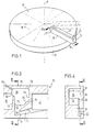
- FIG. 1 shows a rotor of a centrifugal analyzer, designated in its entirety with the reference number 10, which can rotate about an axis of rotation R. It is shown in a highly simplified manner and essentially consists of a rotor base 12 on which a plurality of insert elements 14 can be fastened in different positions, only one insert element 14 being shown in the figure for clarity and a further one being indicated by dash-dotted lines.
- the insert elements 14 extend essentially in the radial direction along the dash-dotted lines 16. They each consist essentially of a base body 18 and a cover part 20. 1 shows the sample chamber opening 22 and the cuvette window 24.
- FIG. 2 shows details of an insert element 14 which has two control and mixing devices according to the invention 26 and 28 is provided, which are referred to below for the sake of simplicity as mixing valves.
- the flow channel for the liquid in the insert element extends from a sample chamber 3o through a connecting channel 32 and 4 reagent fields 33 to 36 into the storage chamber 38 of the first mixing valve 26. Because of the functioning of the mixing valve 26, which is described in more detail below, the liquid proceeds in the flow channel through the outlet channel 4o into three further reaction fields 41, 42 and 43. From there it arrives in the storage chamber 44 and, specifically controlled on the basis of the function of the mixing valve 28, in the outlet channel 46 and from there into the cuvette 48, which originates from the actual measuring space 5o and a cuvette vestibule 52.
- the insert element 14 is installed on the rotor so that it is arranged substantially radially from the inside out, the sample chamber being closest to the center.
- the "reagent fields" 33 to 36 and 41 to 43 are each connected to one another by overflow channels and can perform different functions and be designed in different ways.
- Fields 33 to 36 preferably contain one or more papers which are provided with dried reagents.
- the reagent field 41 is preferably formed deeper in connection with the function of the mixing valve 26 according to the invention, as can be seen in particular from the top view of the insert element according to FIG. 2b.
- this reagent field merely contains a absorbent fleece as a capillary-active filling which does not carry any reagent. In other cases, however, this fleece is also used as a reagent carrier.
- the reagent zones 42 and 43 meet again similar purposes as the reagent zones 33 to 36, but contain reagents for a second process step of Anal carried out with the insert member 14 sever y drive.
- diluted sample to be analyzed through the opening 22 into the sample chamber 3 0 charged a suitably applied to the rotor is stationary.
- the rotor is then rotated so that the sample solution from the sample chamber reaches the first reagent field 33 and through the further reagent fields 34 to 36 into the first mixing valve 26.
- the reagents contained therein are dissolved and reach the mixing valve 26 with the sample solution.
- the functioning of the reagent carriers contained in the reagent fields and the process of dissolving the reagents is described in more detail in DE-OS 3 0 44 385 which is referred to here.
- the liquid from the first set of reagent fields reaches the storage chamber 38 of the mixing valve 26, where it remains as long as a sufficiently high speed of rotation of the rotor 10 is maintained. This time is determined in particular according to the incubation time of the reaction mixture necessary for the first process step.
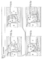
- the structure and function of the mixing valve 26 are described in more detail below with reference to FIGS. 3 to 5.
- FIG. 3 shows an enlarged section of the cross-sectional view according to FIG. 2.
- the end of the reagent field 36 on the side of the accumulation chamber can be seen, which end is closed with a partition 6o, which is inclined obliquely on the side of the reagent field from radially inward downward to radially outward upward.
- the inlet opening 62 of the storage chamber 38 is located above the partition.
- the storage chamber 38 is designed such that it is completely closed in the centrifugal direction, that is to the right in FIG. 3.
- the radially outermost part of the storage chamber is referred to as the storage chamber floor 64.
- the outlet duct 4o leads out of the storage chamber and, as can clearly be seen from the cross section according to FIG. 4, has an elongated, essentially rectangular cross section. It can be clearly seen from FIGS. 4 and 4 that the actual stowage chamber 38 is formed much deeper (distance a), that is to say in the cross-sectional illustration according to FIG. 4 it is much wider than the outlet channel 4o.
- the surface 65 limits the outlet channel together with the inner surface 6 7 of the cover 2o to a width b.
- the surface 65 extends with its area 66 in the storage chamber 38. In the figures, one can see the face 7 0, the b on the radially outer side of the storage chamber 38 by the transition from the large depth a of the storage chamber to the low depth of the outlet channel 7o arises.
- the outlet channel 4o runs in a first section 72 radially inwards and downwards, that is to say with a directional component toward the axis of rotation R.
- the outlet channel runs radially away from the axis of rotation with a directional component. Both sections are separated by the baffle 74.
- the part of the damming wall 74 closest to the axis of rotation R is referred to as the apex 76.
- the second section of the outlet channel opens in the centrifugal direction into a receiving space which is formed by the reagent field 41 in the mixing valve 26 shown here.
- the outlet channel 46 of the mixing valve 28 opens into the cell space 52 (FIG. 2).
- Essential is that the end of the outlet channel, that is to say its mouth into the adjoining receiving space 41 or 52, lies further away from the axis of rotation than the radially outermost part of the storage chamber.
- FIG. 3 shows an overflow channel 78 in the upper wall 79 of the storage chamber 38, through which a liquid volume exceeding a certain limit value can flow out at the first speed.
- This overflow channel 78 is only necessary if the storage chamber 38 is to be used at the same time in a manner known per se to limit the volume flow passed on from the mixing valve 26. It is therefore shown in dashed lines in the drawing.
- FIG. 5 a shows the stage at which the liquid is thrown out of the last reagent field 36 of the first stage at a sufficiently high speed (1000 revolutions / minute in the example) and reaches the storage chamber 38.
- This speed must be so high that the liquid is pressed against the storage chamber bottom 64 by centrifugal force.
- a more or less strongly curved and inclined liquid surface 8 0 is formed .
- the speed must be so high that the liquid in the force play between the centrifugal force and the capillary force counteracting it in the first section 72 of the outlet channel does not penetrate further than a maximum up to the apex 76 in the outlet channel.
- Figure 5b shows the state during rotation at the first speed.
- the figure also shows the function of the optionally provided upper run channel 78, which is located at the point at which the liquid surface 8o ends at the corresponding speed and the desired maximum volume.
- FIG. 5c shows the liquid flowing out through the outlet channel 4o.
- the speed has been considerably reduced, for example to about 50 revolutions / minute. This makes the surface 80 much less steep because the centrifugal force at this low speed is less strong than gravity.
- the first portion 72 now prevails the outlet channel 4 0, which is substantially opposite to the centrifugal direction, the capillary force against the centrifugal force.
- both forces act in the same direction because it has a directional component in the direction of centrifugation.
- the outlet channel is filled with liquid due to the capillary force.
- FIG. 5d shows a process stage in which the speed of rotation was slowly increased again. This may only happen when the liquid in the outlet channel has reached a point which is further away from the axis of rotation than the storage chamber floor 64. If the speed is slowly increased again in this state (as shown, for example, in FIG. 5c), the liquid particles act in the part of the outlet channel 4o facing away from the storage chamber 38, stronger forces in the centrifugation force field than on the water particles of the liquid located in the part of the outlet channel 4o on the side of the storage chamber. This effect is comparable to the principle of action of a suction lifter used in the chemical laboratory in the gravitational field. When the rotor accelerates slowly. the liquid is thereby driven into the receiving space 41 or 52.
- FIG. 5d shows the state in which the entire liquid has just passed the apex 76 and can be accelerated again to the full first speed.
- the stowage chamber 38 can be designed in various ways, the most sensible design for the individual case being able to be determined by tests. In any case, their capacity at the first speed must be greater than the maximum volume of the liquid. For the effect according to the invention, it is favorable if the storage chamber 38 has a wetted surface which is relatively small in relation to the volume. Because, for practical reasons, it preferably consists of the same material as the outlet channel, its surface is also wetted by the liquid. This effect would counteract the desired capillary action of the outlet channel 4 0 if the storage chamber 38 were made too narrow.
- the outlet channel 40 itself can also be varied widely within the scope of the present invention.
- the desired capillary effect can also be achieved by a corresponding fiber filling or, for example, by a groove profile.
- the force with which the liquid is drawn into the capillary gap of the outlet channel 40 is determined on the one hand by the wetting properties of the material and on the other hand by the characteristic width b of the capillary gap.
- the optimal relation of the capillary gap cross-section, in particular the characteristic width b, the material used and the course of the outlet channel 40 can be determined by experiments.
- outlet channel 40 in which it is forcibly wetted in its area defined by the area 66 of the surface 65 during rotation at the first speed, is particularly preferred since the reliability of the device according to the invention is thereby increased.
- the receiving space 41 is preferably provided with a capillary-active filling or design. This means that there is, for example, a fleece through which the liquid, when it has completely filled the outlet channel, is sucked into the receiving space.
- a fleece through which the liquid, when it has completely filled the outlet channel, is sucked into the receiving space.
- the outlet channel 40 in its second section 73 runs in the centrifugal direction. It could, for example, also run directly vertically downward from the stowage chamber 38, so that when the speed is reduced, the liquid is only conveyed into the receiving space 41 by capillary force and not, as described above, by an additional centrifugal effect.
- polymethyl methacrylate is used as the material for the insert element, which has the necessary wetting properties compared to the liquids customary in clinical analysis. If the insert element is to be produced in large numbers as an injection molded plastic part, polystyrene is particularly suitable as the material.
- an outlet channel with a characteristic width between 0.2 and 1 mm has been found in practical tests. preferably 0.5 mm proven, the longitudinal dimension of the cross section was approximately 2 to 4 mm.
- the described mixing valves 26 and 28 according to the invention not only allow the control of the liquid flow, in particular in the case of multi-stage analytical processes, but also a very good mixing of the liquid is achieved.
- This initially unexpected effect of the construction according to the invention can probably be explained in such a way that layers of different concentrations initially form in the storage chamber 38 and mix only relatively slowly. When the speed is reduced, these layers then enter the outlet channel 4o essentially in parallel. There they are mixed during the runout.
- the mixing valve 26 has undergone by lowering and re-increasing the rotational speed to be examined liquid in the insert member 14, s reaches i e as described in the reagent pad 41, which acts as a receiving chamber.
- this reagent field is preferably made deeper than the other reagent fields, so that the entire volume of liquid can be taken up in this reagent field. From there it arrives at a further increased rotation number through the reagent fields 42 and 43, possibly filled with appropriate dry reagents or other devices described in DE-OS 3o 44 385, into the second mixing valve 28.
- the liquid remains, as in the first mixing valve 26, as long as the first higher speed is maintained becomes.
- the speed is reduced and increased again after filling the outlet capillary 46, so that the liquid due to the mode of operation of the mixing valve 28 according to the invention in the cuvette antechamber 52 and from there into the measuring space 5o penetrates.
- the second mixing valve is also expediently provided when the reaction sequence does not require a second incubation time, because in this case too, the device according to the invention brings about a particularly intensive and rapid homogenization of the liquid fed into the storage chamber 44.
Priority Applications (1)
| Application Number | Priority Date | Filing Date | Title |
|---|---|---|---|
| AT82107971T ATE21171T1 (de) | 1981-09-01 | 1982-08-30 | Vorrichtung und verfahren zum steuern und mischen eines der zentrifugalkraft ausgesetzten fluessigkeitsstromes. |
Applications Claiming Priority (2)
| Application Number | Priority Date | Filing Date | Title |
|---|---|---|---|
| DE3134560 | 1981-09-01 | ||
| DE19813134560 DE3134560A1 (de) | 1981-09-01 | 1981-09-01 | Vorrichtung und verfahren zum steuern und mischen einer der zentrifugalkraft ausgesetzten fluessigkeitsstroemung |
Publications (2)
| Publication Number | Publication Date |
|---|---|
| EP0073512A1 true EP0073512A1 (fr) | 1983-03-09 |
| EP0073512B1 EP0073512B1 (fr) | 1986-07-30 |
Family
ID=6140584
Family Applications (1)
| Application Number | Title | Priority Date | Filing Date |
|---|---|---|---|
| EP82107971A Expired EP0073512B1 (fr) | 1981-09-01 | 1982-08-30 | Dispositif et procédé pour contrôler et mélanger un liquide exposé à une force centrifuge |
Country Status (9)
| Country | Link |
|---|---|
| US (1) | US4557600A (fr) |
| EP (1) | EP0073512B1 (fr) |
| JP (1) | JPS5847260A (fr) |
| AT (1) | ATE21171T1 (fr) |
| AU (1) | AU550123B2 (fr) |
| CA (1) | CA1190765A (fr) |
| DE (2) | DE3134560A1 (fr) |
| DK (1) | DK383582A (fr) |
| ES (1) | ES8305223A1 (fr) |
Cited By (13)
| Publication number | Priority date | Publication date | Assignee | Title |
|---|---|---|---|---|
| US4462964A (en) * | 1982-01-14 | 1984-07-31 | Jean Guigan | Conditioning device for preparing multiple analyses |
| EP0132510A2 (fr) * | 1983-04-25 | 1985-02-13 | Roche Diagnostics GmbH | Appareil d'analyse pour la détermination photométrique d'un paramètre d'un fluide |
| EP0160282A2 (fr) * | 1984-05-03 | 1985-11-06 | Abbott Laboratories | Carte de traitement pour centrifuge |
| EP0167175A2 (fr) * | 1984-07-06 | 1986-01-08 | Roche Diagnostics GmbH | Dispositif pour le lavage d'une substance se trouvant dans un champ au moyen d'un fluide de lavage en plusieurs étapes de lavage et pour le transport dans une cuvette du fluide de lavage sortant dudit champ lors de la dernière étape de lavage |
| EP0167171A2 (fr) * | 1984-07-06 | 1986-01-08 | Roche Diagnostics GmbH | Méthode et dispositif pour l'exécution de déterminations analytiques |
| FR2575293A1 (fr) * | 1984-12-21 | 1986-06-27 | Inovelf Sa | Rotor a pipetage dynamique pour dispositif d'analyse a centrifugation |
| GB2186081A (en) * | 1986-02-04 | 1987-08-05 | Orion Yhtymae Oy | Liquid analysis and analytical element |
| US4812411A (en) * | 1984-12-21 | 1989-03-14 | Jean Guigan | Method of performing medical analyses, and a conditioning strip and apparatus for performing the method |
| US4857274A (en) * | 1986-06-26 | 1989-08-15 | Kis Photo Industrie | Device for analyzing a liquid sample |
| US4902479A (en) * | 1983-11-07 | 1990-02-20 | Fisher Scientific Company | Centrifugal analyzer rotor |
| US4999304A (en) * | 1987-12-28 | 1991-03-12 | Miles Inc. | Dynamic braking centrifuge |
| US6783993B1 (en) | 1999-03-25 | 2004-08-31 | Alphahelix Ab | Homogenizing of small-volume mixtures by centrifugation and heating |
| EP2214027A1 (fr) * | 2007-11-20 | 2010-08-04 | Toray Industries, Inc. | Cristaux d'alimentation en liquide et procédé d'analyse |
Families Citing this family (31)
| Publication number | Priority date | Publication date | Assignee | Title |
|---|---|---|---|---|
| US4883763A (en) * | 1984-05-03 | 1989-11-28 | Abbott Laboratories | Sample processor card for centrifuge |
| JPS61139756A (ja) * | 1984-12-12 | 1986-06-27 | Hitachi Koki Co Ltd | 遠心式自動反応装置 |
| FR2579755B1 (fr) * | 1985-03-26 | 1988-04-15 | Guigan Jean | Procede pour la realisation d'analyses medicales d'un echantillon liquide a l'aide de reactifs secs, et dispositif pour la mise en oeuvre du procede |
| GB8514590D0 (en) * | 1985-06-10 | 1985-07-10 | Shandon Southern Prod | Centrifugation |
| US4695164A (en) * | 1985-09-24 | 1987-09-22 | Boehringer Mannheim Gmbh | Position detector and mount therefor for a centrifugal analyzer |
| US4762683A (en) * | 1986-09-16 | 1988-08-09 | E. I. Du Pont De Nemours And Company | Analysis device |
| US4775515A (en) * | 1986-11-18 | 1988-10-04 | Cottingham Hugh V | Agglutinographic slide |
| US4847205A (en) * | 1987-04-08 | 1989-07-11 | Martin Marietta Energy Systems, Inc. | Device and method for automated separation of a sample of whole blood into aliquots |
| US5173262A (en) * | 1987-07-17 | 1992-12-22 | Martin Marietta Energy Systems, Inc. | Rotor assembly and method for automatically processing liquids |
| US5242803A (en) * | 1987-07-17 | 1993-09-07 | Martin Marietta Energy Systems, Inc. | Rotor assembly and assay method |
| JPH0633765B2 (ja) * | 1987-11-28 | 1994-05-02 | 株式会社三ツ葉電機製作所 | 磁石発電機の回転子およびその製造方法 |
| US5209904A (en) * | 1987-12-23 | 1993-05-11 | Abbott Laboratories | Agglutination reaction device utilizing selectively impregnated porous material |
| DE3814585A1 (de) * | 1988-04-29 | 1989-11-09 | Hoffmann La Roche | Testelement fuer agglutinationsuntersuchungen, verfahren zu seiner herstellung und dessen verwendung |
| US5256376A (en) * | 1991-09-12 | 1993-10-26 | Medical Laboratory Automation, Inc. | Agglutination detection apparatus |
| EP1577010A3 (fr) * | 1995-12-05 | 2005-11-16 | Tecan Trading AG | Plate-forme à microsystème et son utilisage |
| ES2282150T3 (es) * | 1999-11-15 | 2007-10-16 | I-Stat Corporation | Aparato y metodos para someter a ensayo la coagulacion en muestras de fluidos. |
| JP2005345160A (ja) * | 2004-05-31 | 2005-12-15 | Advance Co Ltd | 生体情報分析ユニット |
| JP4645211B2 (ja) * | 2005-02-07 | 2011-03-09 | パナソニック株式会社 | Hdl−コレステロール分析用ディスク、及びhdl−コレステロール分析用装置 |
| JP2006247492A (ja) * | 2005-03-09 | 2006-09-21 | Ebara Corp | 固相合成装置 |
| JP4906362B2 (ja) | 2006-01-30 | 2012-03-28 | 株式会社日立ハイテクノロジーズ | 化学分析前処理装置 |
| WO2007105764A1 (fr) * | 2006-03-16 | 2007-09-20 | Matsushita Electric Industrial Co., Ltd. | Disque pour analyse d'echantillon de liquide |
| JP4842796B2 (ja) * | 2006-12-26 | 2011-12-21 | 株式会社日立エンジニアリング・アンド・サービス | 微生物検査装置及び微生物検査用計測チップ |
| JP4614992B2 (ja) * | 2007-07-27 | 2011-01-19 | パナソニック株式会社 | 分析用デバイスとこれを使用する分析装置および分析方法 |
| US8197774B2 (en) * | 2007-12-27 | 2012-06-12 | Rohm Co., Ltd. | Microchip |
| JP5716276B2 (ja) * | 2008-01-28 | 2015-05-13 | 東レ株式会社 | 分離チップおよび分離方法 |
| JP5504690B2 (ja) * | 2008-05-15 | 2014-05-28 | 東レ株式会社 | 分析チップ |
| EP2302396B1 (fr) | 2008-07-17 | 2018-09-26 | PHC Holdings Corporation | Dispositif d'analyse, et procédé d'analyse utilisant le dispositif d'analyse |
| USD962471S1 (en) | 2013-03-13 | 2022-08-30 | Abbott Laboratories | Reagent container |
| USD978375S1 (en) | 2013-03-13 | 2023-02-14 | Abbott Laboratories | Reagent container |
| US9535082B2 (en) | 2013-03-13 | 2017-01-03 | Abbott Laboratories | Methods and apparatus to agitate a liquid |
| US10058866B2 (en) | 2013-03-13 | 2018-08-28 | Abbott Laboratories | Methods and apparatus to mitigate bubble formation in a liquid |
Citations (6)
| Publication number | Priority date | Publication date | Assignee | Title |
|---|---|---|---|---|
| US4035156A (en) * | 1977-01-21 | 1977-07-12 | The United States Of America As Represented By The United States Energy Research And Development Administration | Filter type rotor for multistation photometer |
| DE2347465B2 (de) * | 1972-09-22 | 1977-07-21 | Optischer analysator vom drehkuevettentyp | |
| DE2009993B2 (de) * | 1969-03-13 | 1978-05-24 | Atomic Energy Commission | Vorrichtung zur photometrischen Analyse |
| DE2022084B2 (de) * | 1969-05-23 | 1979-03-08 | United States Atomic Energy Commission, Washington, D.C. | Photometrischer Flussigkeitsanalysator vom Drehküvettentyp |
| US4284602A (en) * | 1979-12-10 | 1981-08-18 | Immutron, Inc. | Integrated fluid manipulator |
| DE3044385A1 (de) * | 1980-11-25 | 1982-06-24 | Boehringer Mannheim Gmbh, 6800 Mannheim | Verfahren zur durchfuehrung analytischer bestimmungen und hierfuer geeignetes rotoreinsatzelement |
Family Cites Families (5)
| Publication number | Priority date | Publication date | Assignee | Title |
|---|---|---|---|---|
| US3555284A (en) * | 1968-12-18 | 1971-01-12 | Norman G Anderson | Multistation, single channel analytical photometer and method of use |
| DE2220016C3 (de) * | 1972-04-24 | 1980-06-12 | Henkel Kgaa, 4000 Duesseldorf | Umsetzungsprodukte von e - Caprolactam mit 13-Propandiaminen, Verfahren zu deren Herstellung und deren Verwendung |
| US3795451A (en) * | 1973-04-24 | 1974-03-05 | Atomic Energy Commission | Rotor for fast analyzer of rotary cuvette type |
| US3829223A (en) * | 1973-07-20 | 1974-08-13 | Atomic Energy Commission | Mixing rotor for fast analyzer of rotary cuvette type with means for enhancing the mixing of sample and reagent liquids |
| US3873217A (en) * | 1973-07-24 | 1975-03-25 | Atomic Energy Commission | Simplified rotor for fast analyzer of rotary cuvette type |
-
1981
- 1981-09-01 DE DE19813134560 patent/DE3134560A1/de not_active Withdrawn
-
1982
- 1982-08-24 AU AU87556/82A patent/AU550123B2/en not_active Ceased
- 1982-08-26 ES ES515257A patent/ES8305223A1/es not_active Expired
- 1982-08-27 DK DK383582A patent/DK383582A/da not_active Application Discontinuation
- 1982-08-30 CA CA000410448A patent/CA1190765A/fr not_active Expired
- 1982-08-30 EP EP82107971A patent/EP0073512B1/fr not_active Expired
- 1982-08-30 JP JP57149355A patent/JPS5847260A/ja active Granted
- 1982-08-30 US US06/413,011 patent/US4557600A/en not_active Expired - Fee Related
- 1982-08-30 DE DE8282107971T patent/DE3272314D1/de not_active Expired
- 1982-08-30 AT AT82107971T patent/ATE21171T1/de not_active IP Right Cessation
Patent Citations (6)
| Publication number | Priority date | Publication date | Assignee | Title |
|---|---|---|---|---|
| DE2009993B2 (de) * | 1969-03-13 | 1978-05-24 | Atomic Energy Commission | Vorrichtung zur photometrischen Analyse |
| DE2022084B2 (de) * | 1969-05-23 | 1979-03-08 | United States Atomic Energy Commission, Washington, D.C. | Photometrischer Flussigkeitsanalysator vom Drehküvettentyp |
| DE2347465B2 (de) * | 1972-09-22 | 1977-07-21 | Optischer analysator vom drehkuevettentyp | |
| US4035156A (en) * | 1977-01-21 | 1977-07-12 | The United States Of America As Represented By The United States Energy Research And Development Administration | Filter type rotor for multistation photometer |
| US4284602A (en) * | 1979-12-10 | 1981-08-18 | Immutron, Inc. | Integrated fluid manipulator |
| DE3044385A1 (de) * | 1980-11-25 | 1982-06-24 | Boehringer Mannheim Gmbh, 6800 Mannheim | Verfahren zur durchfuehrung analytischer bestimmungen und hierfuer geeignetes rotoreinsatzelement |
Cited By (24)
| Publication number | Priority date | Publication date | Assignee | Title |
|---|---|---|---|---|
| US4462964A (en) * | 1982-01-14 | 1984-07-31 | Jean Guigan | Conditioning device for preparing multiple analyses |
| EP0132510A3 (fr) * | 1983-04-25 | 1987-12-16 | Roche Diagnostics GmbH | Appareil d'analyse pour la détermination photométrique d'un paramètre d'un fluide |
| EP0132510A2 (fr) * | 1983-04-25 | 1985-02-13 | Roche Diagnostics GmbH | Appareil d'analyse pour la détermination photométrique d'un paramètre d'un fluide |
| US4902479A (en) * | 1983-11-07 | 1990-02-20 | Fisher Scientific Company | Centrifugal analyzer rotor |
| EP0160282A2 (fr) * | 1984-05-03 | 1985-11-06 | Abbott Laboratories | Carte de traitement pour centrifuge |
| EP0160282A3 (en) * | 1984-05-03 | 1986-03-05 | Abbott Laboratories | Processor card for centrifuge |
| US4915911A (en) * | 1984-07-06 | 1990-04-10 | Boehringer Mannheim Gmbh | Device for rinsing out a substance present in a zone |
| EP0167175A2 (fr) * | 1984-07-06 | 1986-01-08 | Roche Diagnostics GmbH | Dispositif pour le lavage d'une substance se trouvant dans un champ au moyen d'un fluide de lavage en plusieurs étapes de lavage et pour le transport dans une cuvette du fluide de lavage sortant dudit champ lors de la dernière étape de lavage |
| EP0167175A3 (en) * | 1984-07-06 | 1987-09-30 | Boehringer Mannheim Gmbh | Device for washing a substance present in a field with a washing liquid in several washing steps and for transporting the washing fluid, emerging from said field, after the last washing step to a tray |
| EP0167171A3 (en) * | 1984-07-06 | 1988-06-22 | Boehringer Mannheim Gmbh | Method and device for performing analytical determinations |
| EP0167171A2 (fr) * | 1984-07-06 | 1986-01-08 | Roche Diagnostics GmbH | Méthode et dispositif pour l'exécution de déterminations analytiques |
| US4894204A (en) * | 1984-12-21 | 1990-01-16 | Inovelf | Rotor with dynamic pipeting for a centrifuge analysis device |
| EP0191257A1 (fr) * | 1984-12-21 | 1986-08-20 | INOVELF, Société anonyme dite: | Rotor à pipetage dynamique pour dispositif d'analyse à centrifugation |
| FR2575293A1 (fr) * | 1984-12-21 | 1986-06-27 | Inovelf Sa | Rotor a pipetage dynamique pour dispositif d'analyse a centrifugation |
| US4812411A (en) * | 1984-12-21 | 1989-03-14 | Jean Guigan | Method of performing medical analyses, and a conditioning strip and apparatus for performing the method |
| GB2186081B (en) * | 1986-02-04 | 1990-10-17 | Orion Yhtymae Oy | A method for performing a liquid analysis and an analytical device for use in the method. |
| BE1001166A5 (fr) * | 1986-02-04 | 1989-08-08 | Orion Yhtymae Oy | Procede d'analyse de liquides et element d'analyse a utiliser dans le procede. |
| FR2593920A1 (fr) * | 1986-02-04 | 1987-08-07 | Orion Yhtymae Oy | Procede d'analyse de liquides et elements d'analyse a utiliser dans le procede |
| GB2186081A (en) * | 1986-02-04 | 1987-08-05 | Orion Yhtymae Oy | Liquid analysis and analytical element |
| US4857274A (en) * | 1986-06-26 | 1989-08-15 | Kis Photo Industrie | Device for analyzing a liquid sample |
| US4999304A (en) * | 1987-12-28 | 1991-03-12 | Miles Inc. | Dynamic braking centrifuge |
| US6783993B1 (en) | 1999-03-25 | 2004-08-31 | Alphahelix Ab | Homogenizing of small-volume mixtures by centrifugation and heating |
| EP2214027A1 (fr) * | 2007-11-20 | 2010-08-04 | Toray Industries, Inc. | Cristaux d'alimentation en liquide et procédé d'analyse |
| EP2214027A4 (fr) * | 2007-11-20 | 2015-06-03 | Toray Industries | Cristaux d'alimentation en liquide et procédé d'analyse |
Also Published As
| Publication number | Publication date |
|---|---|
| EP0073512B1 (fr) | 1986-07-30 |
| ES515257A0 (es) | 1983-05-01 |
| JPH0224470B2 (fr) | 1990-05-29 |
| ES8305223A1 (es) | 1983-05-01 |
| JPS5847260A (ja) | 1983-03-18 |
| DE3134560A1 (de) | 1983-03-17 |
| ATE21171T1 (de) | 1986-08-15 |
| DE3272314D1 (en) | 1986-09-04 |
| AU550123B2 (en) | 1986-03-06 |
| DK383582A (da) | 1983-03-02 |
| AU8755682A (en) | 1983-03-10 |
| CA1190765A (fr) | 1985-07-23 |
| US4557600A (en) | 1985-12-10 |
Similar Documents
| Publication | Publication Date | Title |
|---|---|---|
| EP0073512B1 (fr) | Dispositif et procédé pour contrôler et mélanger un liquide exposé à une force centrifuge | |
| EP2072131B1 (fr) | Elément microfluide destiné au mélange d'un liquide dans un réactif | |
| EP0039825B1 (fr) | Rotor à cuvettes pour appareil d'analyse et procédé pour l'operation dudit rotor à cuvettes | |
| DE2260292C2 (de) | Fotometrischer Analysator | |
| DE4293865B4 (de) | Verbesserte Cytozentrifugiereinrichtung, Apparatur und Verfahren | |
| DE69730893T2 (de) | Vorbehandlungsgerät | |
| EP0073513B1 (fr) | Méthode d'exécution d'une détermination analytique et moyen approprié | |
| EP1685900B1 (fr) | Utilisation d'un dispositif pour l'analyse d'un échantillon de liquide | |
| EP0052770A1 (fr) | Rotor muni de segments amovibles pour analyseur centrifuge | |
| EP2632591B1 (fr) | Élément microfluidique pour l'analyse d'un échantillon liquide | |
| EP1761757A1 (fr) | Dispositif pour recueillir du sang et separer des constituants sanguins, procede pour separer des constituants sanguins et utilisation dudit dispositif | |
| DE2458384A1 (de) | Mehrproben-rotoranordnung zur herstellung von blutfraktionen | |
| EP0371003A2 (fr) | Appareil pour la détermination analytique de composants d'un fluide corporel | |
| DE3151291A1 (de) | Geraet zur analyse von biologischen fluiden | |
| DD202072A5 (de) | Verfahren zur durchfuehrung analytischer bestimmungen und hierfuer geeignetes rotoreinsatzelement | |
| DE2103841A1 (de) | Blutuntersuchungsvorrichtung | |
| EP3592463B1 (fr) | Procédé de commutation centrifugo-pneumatique de liquide | |
| EP0668496A2 (fr) | Cuvette pour mesurage optique | |
| DE2432498C3 (de) | Analysenzentrifuge | |
| EP0405162B1 (fr) | Rotor des cuves | |
| DE102006025477B4 (de) | Küvette und Verfahren zu ihrer Herstellung | |
| DE3333674C2 (de) | Durchsichtiger Objektträger für die mikroskopische Untersuchung von Flüssigkeitsproben | |
| DE2117423C3 (fr) | ||
| DE2336619A1 (de) | Fotometrischer analysator | |
| EP1533035A1 (fr) | Porte-échantillon |
Legal Events
| Date | Code | Title | Description |
|---|---|---|---|
| PUAI | Public reference made under article 153(3) epc to a published international application that has entered the european phase |
Free format text: ORIGINAL CODE: 0009012 |
|
| 17P | Request for examination filed |
Effective date: 19820830 |
|
| AK | Designated contracting states |
Designated state(s): AT BE CH DE FR GB IT LI LU NL SE |
|
| GRAA | (expected) grant |
Free format text: ORIGINAL CODE: 0009210 |
|
| AK | Designated contracting states |
Kind code of ref document: B1 Designated state(s): AT BE CH DE FR GB IT LI LU NL SE |
|
| REF | Corresponds to: |
Ref document number: 21171 Country of ref document: AT Date of ref document: 19860815 Kind code of ref document: T |
|
| PG25 | Lapsed in a contracting state [announced via postgrant information from national office to epo] |
Ref country code: LU Free format text: LAPSE BECAUSE OF NON-PAYMENT OF DUE FEES Effective date: 19860831 |
|
| PGFP | Annual fee paid to national office [announced via postgrant information from national office to epo] |
Ref country code: NL Payment date: 19860831 Year of fee payment: 5 |
|
| REF | Corresponds to: |
Ref document number: 3272314 Country of ref document: DE Date of ref document: 19860904 |
|
| ITF | It: translation for a ep patent filed |
Owner name: ING. C. GREGORJ S.P.A. |
|
| ET | Fr: translation filed | ||
| PLBE | No opposition filed within time limit |
Free format text: ORIGINAL CODE: 0009261 |
|
| STAA | Information on the status of an ep patent application or granted ep patent |
Free format text: STATUS: NO OPPOSITION FILED WITHIN TIME LIMIT |
|
| 26N | No opposition filed | ||
| PG25 | Lapsed in a contracting state [announced via postgrant information from national office to epo] |
Ref country code: SE Effective date: 19870831 |
|
| BERE | Be: lapsed |
Owner name: BOEHRINGER MANNHEIM G.M.B.H. Effective date: 19870831 |
|
| PG25 | Lapsed in a contracting state [announced via postgrant information from national office to epo] |
Ref country code: NL Effective date: 19880301 |
|
| NLV4 | Nl: lapsed or anulled due to non-payment of the annual fee | ||
| PG25 | Lapsed in a contracting state [announced via postgrant information from national office to epo] |
Ref country code: BE Effective date: 19890831 |
|
| ITTA | It: last paid annual fee | ||
| EUG | Se: european patent has lapsed |
Ref document number: 82107971.2 Effective date: 19880711 |
|
| PGFP | Annual fee paid to national office [announced via postgrant information from national office to epo] |
Ref country code: FR Payment date: 19950809 Year of fee payment: 14 |
|
| PGFP | Annual fee paid to national office [announced via postgrant information from national office to epo] |
Ref country code: AT Payment date: 19950811 Year of fee payment: 14 |
|
| PGFP | Annual fee paid to national office [announced via postgrant information from national office to epo] |
Ref country code: GB Payment date: 19950821 Year of fee payment: 14 |
|
| PGFP | Annual fee paid to national office [announced via postgrant information from national office to epo] |
Ref country code: CH Payment date: 19950828 Year of fee payment: 14 |
|
| PGFP | Annual fee paid to national office [announced via postgrant information from national office to epo] |
Ref country code: DE Payment date: 19950829 Year of fee payment: 14 |
|
| PG25 | Lapsed in a contracting state [announced via postgrant information from national office to epo] |
Ref country code: GB Effective date: 19960830 Ref country code: AT Effective date: 19960830 |
|
| PG25 | Lapsed in a contracting state [announced via postgrant information from national office to epo] |
Ref country code: LI Effective date: 19960831 Ref country code: CH Effective date: 19960831 |
|
| REG | Reference to a national code |
Ref country code: CH Ref legal event code: PL |
|
| GBPC | Gb: european patent ceased through non-payment of renewal fee |
Effective date: 19960830 |
|
| PG25 | Lapsed in a contracting state [announced via postgrant information from national office to epo] |
Ref country code: FR Effective date: 19970430 |
|
| PG25 | Lapsed in a contracting state [announced via postgrant information from national office to epo] |
Ref country code: DE Effective date: 19970501 |
|
| REG | Reference to a national code |
Ref country code: FR Ref legal event code: ST |