EP0073073B1 - Mounting shell formed with cuts for an apparatus - Google Patents
Mounting shell formed with cuts for an apparatus Download PDFInfo
- Publication number
- EP0073073B1 EP0073073B1 EP82200925A EP82200925A EP0073073B1 EP 0073073 B1 EP0073073 B1 EP 0073073B1 EP 82200925 A EP82200925 A EP 82200925A EP 82200925 A EP82200925 A EP 82200925A EP 0073073 B1 EP0073073 B1 EP 0073073B1
- Authority
- EP
- European Patent Office
- Prior art keywords
- mounting
- shell
- tongues
- wall
- walls
- Prior art date
- Legal status (The legal status is an assumption and is not a legal conclusion. Google has not performed a legal analysis and makes no representation as to the accuracy of the status listed.)
- Expired
Links
Images
Classifications
-
- B—PERFORMING OPERATIONS; TRANSPORTING
- B60—VEHICLES IN GENERAL
- B60K—ARRANGEMENT OR MOUNTING OF PROPULSION UNITS OR OF TRANSMISSIONS IN VEHICLES; ARRANGEMENT OR MOUNTING OF PLURAL DIVERSE PRIME-MOVERS IN VEHICLES; AUXILIARY DRIVES FOR VEHICLES; INSTRUMENTATION OR DASHBOARDS FOR VEHICLES; ARRANGEMENTS IN CONNECTION WITH COOLING, AIR INTAKE, GAS EXHAUST OR FUEL SUPPLY OF PROPULSION UNITS IN VEHICLES
- B60K35/00—Instruments specially adapted for vehicles; Arrangement of instruments in or on vehicles
- B60K35/50—Instruments characterised by their means of attachment to or integration in the vehicle
-
- B—PERFORMING OPERATIONS; TRANSPORTING
- B60—VEHICLES IN GENERAL
- B60R—VEHICLES, VEHICLE FITTINGS, OR VEHICLE PARTS, NOT OTHERWISE PROVIDED FOR
- B60R11/00—Arrangements for holding or mounting articles, not otherwise provided for
- B60R11/02—Arrangements for holding or mounting articles, not otherwise provided for for radio sets, television sets, telephones, or the like; Arrangement of controls thereof
-
- H—ELECTRICITY
- H05—ELECTRIC TECHNIQUES NOT OTHERWISE PROVIDED FOR
- H05K—PRINTED CIRCUITS; CASINGS OR CONSTRUCTIONAL DETAILS OF ELECTRIC APPARATUS; MANUFACTURE OF ASSEMBLAGES OF ELECTRICAL COMPONENTS
- H05K5/00—Casings, cabinets or drawers for electric apparatus
- H05K5/02—Details
- H05K5/0204—Mounting supporting structures on the outside of casings
-
- B—PERFORMING OPERATIONS; TRANSPORTING
- B60—VEHICLES IN GENERAL
- B60R—VEHICLES, VEHICLE FITTINGS, OR VEHICLE PARTS, NOT OTHERWISE PROVIDED FOR
- B60R11/00—Arrangements for holding or mounting articles, not otherwise provided for
- B60R11/02—Arrangements for holding or mounting articles, not otherwise provided for for radio sets, television sets, telephones, or the like; Arrangement of controls thereof
- B60R11/0205—Arrangements for holding or mounting articles, not otherwise provided for for radio sets, television sets, telephones, or the like; Arrangement of controls thereof for radio sets
-
- B—PERFORMING OPERATIONS; TRANSPORTING
- B60—VEHICLES IN GENERAL
- B60R—VEHICLES, VEHICLE FITTINGS, OR VEHICLE PARTS, NOT OTHERWISE PROVIDED FOR
- B60R11/00—Arrangements for holding or mounting articles, not otherwise provided for
- B60R2011/0001—Arrangements for holding or mounting articles, not otherwise provided for characterised by position
- B60R2011/0003—Arrangements for holding or mounting articles, not otherwise provided for characterised by position inside the vehicle
- B60R2011/0005—Dashboard
-
- B—PERFORMING OPERATIONS; TRANSPORTING
- B60—VEHICLES IN GENERAL
- B60R—VEHICLES, VEHICLE FITTINGS, OR VEHICLE PARTS, NOT OTHERWISE PROVIDED FOR
- B60R11/00—Arrangements for holding or mounting articles, not otherwise provided for
- B60R2011/0042—Arrangements for holding or mounting articles, not otherwise provided for characterised by mounting means
- B60R2011/0043—Arrangements for holding or mounting articles, not otherwise provided for characterised by mounting means for integrated articles, i.e. not substantially protruding from the surrounding parts
- B60R2011/0045—Arrangements for holding or mounting articles, not otherwise provided for characterised by mounting means for integrated articles, i.e. not substantially protruding from the surrounding parts with visible part, e.g. flush mounted
- B60R2011/0047—Arrangements for holding or mounting articles, not otherwise provided for characterised by mounting means for integrated articles, i.e. not substantially protruding from the surrounding parts with visible part, e.g. flush mounted using hidden fastening means
Definitions
- the invention relates to a metal mounting shell for mounting an apparatus by means of fastening means on the apparatus and on the shell which engage one another when the apparatus is inserted into the shell, said mounting shell being rectangular, parallelepipedal, being inserted into an opening in a mounting wall and being secured to the mounting wall by means of bent tongues, at least one of which tongues is formed in each of four walls of the shell, which walls lie in planes perpendicular to the plane of the mounting wall, by a cut which leaves a bridge portion between the relevant tongue and the shell, the mounting shell comprising an abutment which bears against at least a portion of the mounting wall surrounding the opening with a given force which is produced by the bending of the tongues.
- the bridge portion which connects the tongue to the remainder of the mounting shell is situated near the abutment which is then formed by a flange or upright edge.
- the distance between the bridge portion and the flange or upright edge is dependent on the thickness of the mounting wall.
- each of the tongues comprises a mounting portion and a supporting portion which have been pivoted together about a first axis which extends along the bridge portion and which is perpendicular to the plane of the mounting wall, the supporting portion also being bent relative to the mounting portion about a second axis which is perpendicular to the first axis and which is situated in a plane perpendicular to the plane of the respective wall of the shell, the free end of the supporting portion bearing against the mounting wall with a force which is determined mainly by the degree of deformation of the supporting portion.
- the supporting portion is bent about the second axis which can be situated at a substantial distance from the extreme edge of the mounting shell during mounting as well as during operation, hardly any deformation occurs of the portion of the mounting shell which is situated between the bridge portion and the extreme edge.
- a special embodiment of a mounting shell in accordance with the invention which is suitable for mounting in mounting walls having at least two different nominal thicknesses is characterized in that in each of the four walls of the shell there is provided a pair of pivotable tongues, the two tongues of each pair having free ends which face one another and being situated in a zone which is bounded by the respective two first axes, the supporting portions of the two tongues having a different dimension which is adapted to the thickness of given mounting walls.
- a further special embodiment of a mounting shell in accordance with the invention is characterised in that the first axis extends substantially along said bridge portion and one or more weakened portions adjacent to the bridge portion. Due to the weakened portions the mounting portion extends almost at right angles to the wall of the mounting shell, so that the force exerted on the supporting portion by the mounting wall acts at a comparatively small distance from the first axis.
- Ejection forces are to be understood herein to mean forces which act on the apparatus or the supporting portions of the tongues during acceleration or deceleration of the mounting wall. Such ejection forces can occur in the case of shocks or jolts and during deceleration and acceleration of vehicles or vessels in which the apparatus is mounted.
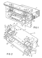
- the apparatus 1 which is shown in Figures 1 and 3 comprises a radio 1 having a customary rectangular box shape.
- Figure 1 shows the radio 1 mounted in a mounting wall 3.
- the mounting wall 3 forms, for example, part of the dashboard of a car, the apparatus being a car radio with cassette player.
- the radio 1 is mounted in the mounting wall 3 by means of a rectangular parallelepipedal metal mounting shell 5 which is shown in the pal- mounting condition in Figure 2. Before the mounting of the radio 1 in the mounting shell 5, the latter must itself be mounted in the mounting wall 3. This situation is illustrated in Figure 3.
- the rectangular parallelepipedal metal mounting shell 5, which is shown in Figure 2, preferably has a wall thickness of 0.5 mm and at its front comprises an abutment which is formed by upright edges or flanges 7 and 9 on the upper and lower walls 11 and 13, respectively, of the mounting shell and by upright edges or flanges 15 and 17 on the right-hand and left-hand side walls 19 and 21, respectively, of the mounting shell.
- the upper wall 11 and the lower wall 13 comprise rectangular tongues 23 which are formed in pairs by cuts in the walls 11 and 12.
- the side walls 19 and 21 also comprise pairs of tongues 23 formed by cuts in these walls.
- the upper wall 11 and the lower wall 13 each comprise two pairs of tongues 23, and the right-hand side wall 19 and the left-hand side wall 21 each comprise one pair of tongues 23.
- each tongue 23 is pivotable and/or bendable about a first axis 25 which extends parallel to the upper and lower walls and the side walls of the mounting shell 5.
- Figure 2 shows only the first axes 25 for the tongues 23 formed in the upper wall 11.
- Each of the first axes 25 extends along a cut 27, a bridge portion 29, a weakened (slotted) portion 31 and a bridge portion 33.
- Each tongue 23 comprises a mounting portion 35 and a supporting portion 37 which are pivotable together about the relevant first axis 25.
- the supporting portion 37 of each of the tongues in the upper wall 11 and the lower wall 13 is bendable relative to the associated mounting portion 35 about a second axis 39 which forms a boundary between the supporting and mounting portions.
- the second axes 39 are situated in a plane which extends perpendicularly to the planes of the upper and lower walls and the side walls of the mounting shell.
- the supporting portion 37 of each of the tongues in the side walls 19 and 21 also is bendable relative to the associated mounting portion 35 about a second axis, namely, the second axis which is denoted by the reference numeral 41.
- the second axes 41 are also situated in a plane which extends perpendicularly to the planes- of the upper and lower walls and the side walls of the mounting shell.
- the axes 39 and 41 extend substantially perpendicularly to one another in the mounted as well as in the non-mounted condition of the mounting shell.
- each cut 27 and the associated bridge portions 29 and 33 and weakened portion 31 enables the respective tongue 23 to be pivoted about the respective axis 25 into an erect position perpendicular to the respective wall 11, 13, 19 or 21 by comparatively small forces without comparatively strong bending, so that it acts as if it were a hinge for the tongue 23.
- An axis 25 can be formed without the provision of the weakened portion 31 by giving a certain length to the cut 27. The bending of the tongue 23 will then be stronger, and the bending force also will be somewhat greater.
- the left-hand pair of tongues 23 in the upper wall 11 is shown erected in Figure 2 as if the mounting shell had already been mounted in a mounting wall.
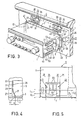
- FIGS 1, 3 and 4 show how the ends 43 of the supporting portions bear against the inner side of the mounting wall 3. It can be seen that the pivoting or bending of the mounting portion 35 takes place in a direction which curves in a first plane which is parallel to the plane of the mounting wall 3 at the area of mounting, whilst the bending of the supporting portion 37 takes place in a direction which curves in a second plane which is perpendicular to the plane of the mounting wall 3 at the area of mounting.
- the mounting shell 5 is inserted into an opening 45 (see the Figures 1 and 3) in the mounting wall 3. This opening is situated in a flat portion of the mounting wall 3.
- the radio 1 is mounted in known manner (said German Patent Application No. 2,903,176) in the mounting shell 5 by means of leaf springs 47 (see Figure 3) which are connected to the left-hand side wall and the right-hand side wall 49 of the radio 1 by means of riveted and/or screwed connections 51 (only the leaf spring 47 on the right-hand side wall 49 is shown).
- the leaf spring 47 comprises two limbs 53 and 55 which are formed with shoulders 56 and 58 which engage the edges of openings 57 and 59 in the relevant side wall 19 of the mounting shell 5. If desired, the radio 1 can be removed from the mounting shell 5 by means of a special tool (not shown).
- the limbs 53 and 55 are deflected into openings 61 and 63 in the side wall 49 of the radio 1.
- the radio 1 is supported in a very stable manner by the mounting shell 5 because a total of twelve supporting tongue portions 37 which are symmetrically distributed over the circumference of the mounting shell press against the inner side of the mounting wall 3 (see Figure 3).
- the distance A between the end 43 of the supporting portion of an erected tongue and the plane of the mounting portion 35 of the tongue is preferably as small as possible, because the smaller the deflection of the supporting portion 37 during the erection of the tongue, the greater will be the resistance to further bending and ultimately folding-over of the supporting portion 37.
- Such optimizing of the length of the supporting portion is determined by the number of mounting walls of different wall thicknesses for which the mounting shell 5 is to be made suitable.
- the preferred embodiment of a mounting shell 5 shown in Figure 5 has been designed for two different wall thicknesses, whilst the mounting shell 5 described above and shown in Figure 2 has been designed for the one wall thickness.
- a somewhat larger number of wall thicknesses around the design value (nominal value) can be covered by some variation of the dimension A ( Figure 4). In the embodiment shown in Figure 5, two ranges of wall thicknesses around the two design values are thus obtained.
- the mounting shell 5 is thus suitable for wall thicknesses having a nominal value D 1 and D 2 by utilizing only the supporting portions of the same length. By allowing a variation of the dimension A ( Figure 4), wall thicknesses around the nominal values D 1 and D 2 are also acceptable.
- the mounting portions 35 of each tongue comprise an additional portion 65 in which there is provided a slot 67 in which a screw driver can be inserted in order to pivot the tongue 23 about the associated axis 25.
Landscapes
- Engineering & Computer Science (AREA)
- Mechanical Engineering (AREA)
- Chemical & Material Sciences (AREA)
- Combustion & Propulsion (AREA)
- Transportation (AREA)
- Microelectronics & Electronic Packaging (AREA)
- Casings For Electric Apparatus (AREA)
- Fittings On The Vehicle Exterior For Carrying Loads, And Devices For Holding Or Mounting Articles (AREA)
- Helmets And Other Head Coverings (AREA)
- Dowels (AREA)
- Buckles (AREA)
Applications Claiming Priority (2)
| Application Number | Priority Date | Filing Date | Title |
|---|---|---|---|
| NL8103575 | 1981-07-29 | ||
| NLAANVRAGE8103575,A NL187144C (nl) | 1981-07-29 | 1981-07-29 | Inbouwapparaat met ingesneden bevestigingshuls en bevestigingshuls voor een dergelijk inbouwapparaat. |
Publications (2)
| Publication Number | Publication Date |
|---|---|
| EP0073073A1 EP0073073A1 (en) | 1983-03-02 |
| EP0073073B1 true EP0073073B1 (en) | 1986-04-23 |
Family
ID=19837867
Family Applications (1)
| Application Number | Title | Priority Date | Filing Date |
|---|---|---|---|
| EP82200925A Expired EP0073073B1 (en) | 1981-07-29 | 1982-07-20 | Mounting shell formed with cuts for an apparatus |
Country Status (9)
| Country | Link |
|---|---|
| US (1) | US4524933A (cg-RX-API-DMAC7.html) |
| EP (1) | EP0073073B1 (cg-RX-API-DMAC7.html) |
| JP (1) | JPS5827396A (cg-RX-API-DMAC7.html) |
| AR (1) | AR230139A1 (cg-RX-API-DMAC7.html) |
| BR (1) | BR8204347A (cg-RX-API-DMAC7.html) |
| CA (1) | CA1184250A (cg-RX-API-DMAC7.html) |
| DE (1) | DE3270756D1 (cg-RX-API-DMAC7.html) |
| ES (1) | ES277886Y (cg-RX-API-DMAC7.html) |
| NL (1) | NL187144C (cg-RX-API-DMAC7.html) |
Families Citing this family (24)
| Publication number | Priority date | Publication date | Assignee | Title |
|---|---|---|---|---|
| NL8303946A (nl) * | 1983-11-17 | 1985-06-17 | Philips Nv | Inbouwapparaat met een montageveer. |
| FR2566163B1 (fr) * | 1984-06-13 | 1990-05-25 | Clarion Co Ltd | Structure de montage et d'enlevement d'un appareil dans une voiture |
| EP0188176A3 (de) * | 1984-12-18 | 1987-05-27 | D P E ELETTROMECCANICA S.r.l. | System zur Befestigung von Funkempfängern an Innenräume von Armaturenbretten oder ähnliche Hohlräume, um den Diebstahl von den erwähnten Funkempfängern zu verhindern |
| SE442459B (sv) * | 1985-02-04 | 1985-12-23 | Gunnar Lith | Utbytbar och lasbar i en ram anordnad forvaringsbox |
| US4660789A (en) * | 1985-06-10 | 1987-04-28 | Scosche Industries, Inc. | Conversion kit for mounting a radio substituted for original radios in automotive vehicles |
| US4756495A (en) * | 1985-06-10 | 1988-07-12 | Scosche Industries, Inc. | Conversion kit for mounting a radio substituted for original radios in automotive vehicles |
| JPH07368Y2 (ja) * | 1985-11-29 | 1995-01-11 | アルパイン株式会社 | 車載用音響機器の取付装置 |
| US4726789A (en) * | 1986-09-02 | 1988-02-23 | Moshe Yaffe | Anti-theft mounting apparatus |
| US4699341A (en) * | 1987-01-05 | 1987-10-13 | Ponticelli Robert J | System for mounting radio equipment in vehicles |
| US4742978A (en) * | 1987-06-04 | 1988-05-10 | Ponticelli Robert J | Universal mounting system for installing vehicle radio equipment |
| US4881910A (en) * | 1987-09-21 | 1989-11-21 | Walter Odemer Co., Inc. | Quick release minimum profile shuttle for vehicle radios and tape players |
| US4911386A (en) * | 1988-05-27 | 1990-03-27 | Scosche Industries, Inc. | Multiple radio in-dash installation kit |
| US4868715A (en) * | 1988-05-31 | 1989-09-19 | Scosche Industries, Inc. | Break-away panel structure for radio in-dash installation kit |
| US4913382A (en) * | 1989-07-24 | 1990-04-03 | Chrysler Corporation | Mounting means for vehicle audio device |
| US5169097A (en) * | 1990-11-27 | 1992-12-08 | Oki Electric Industry Co., Ltd. | Apparatus and method for supporting an accessory unit within an automobile storage area |
| US5169105A (en) * | 1990-11-27 | 1992-12-08 | Oki Electric Industry Co., Ltd. | Apparatus and method for supporting an accessory unit within an automobile console |
| US5560572A (en) * | 1994-09-26 | 1996-10-01 | General Motors Corporation | Instrument panel dovetail slide mounting assembly |
| US5676338A (en) * | 1995-11-27 | 1997-10-14 | Ford Motor Company | Deployable vehicle electronics module assembly |
| GB9603500D0 (en) * | 1996-02-20 | 1996-04-17 | Ford Motor Co | Retaining clip |
| DE19720724C2 (de) * | 1997-05-16 | 1999-09-09 | Siedle & Soehne S | Türanlage |
| DE19832061C1 (de) * | 1998-07-16 | 1999-12-30 | Siemens Ag | Gehäuse eines elektrischen Geräts |
| KR20000060243A (ko) * | 1999-03-12 | 2000-10-16 | 구자홍 | 영상표시기기용 스피커 장착장치 |
| US20060032989A1 (en) * | 2004-08-16 | 2006-02-16 | Badiali John A | Mounting apparatus for marine radio |
| DE102017208381A1 (de) * | 2016-05-27 | 2017-11-30 | Ford Global Technologies, Llc | Befestigungshalter für konsole |
Family Cites Families (10)
| Publication number | Priority date | Publication date | Assignee | Title |
|---|---|---|---|---|
| US1246107A (en) * | 1916-09-05 | 1917-11-13 | Julian H Kendig | Support for electrical fixtures. |
| US2143517A (en) * | 1936-06-16 | 1939-01-10 | Ray Z Huff | Outlet box |
| US2616643A (en) * | 1948-07-08 | 1952-11-04 | Chicago Telephone Supply Corp | Fastening device |
| US2969418A (en) * | 1958-03-03 | 1961-01-24 | Gen Electric | Interchangeable wiring devices |
| US2930505A (en) * | 1959-02-10 | 1960-03-29 | Robert J Meyer | Wall insert for setting bathroom fixtures |
| US3023920A (en) * | 1960-01-14 | 1962-03-06 | Steel City Electric Co | Outlet boxes |
| US3248078A (en) * | 1964-04-30 | 1966-04-26 | Radar Relay Inc | Support bracket |
| US3308260A (en) * | 1966-01-28 | 1967-03-07 | Cutler Hammer Inc | Electric switches |
| US3799483A (en) * | 1972-05-18 | 1974-03-26 | P Chiappinelli | Radio mounting collar |
| DE2903176C2 (de) * | 1979-01-27 | 1983-12-15 | Blaupunkt-Werke Gmbh, 3200 Hildesheim | Einbaueinrichtung für Zusatzgeräte in vorgegebenen Einbauöffnungen |
-
1981
- 1981-07-29 NL NLAANVRAGE8103575,A patent/NL187144C/xx not_active IP Right Cessation
-
1982
- 1982-07-07 AR AR289926A patent/AR230139A1/es active
- 1982-07-20 DE DE8282200925T patent/DE3270756D1/de not_active Expired
- 1982-07-20 EP EP82200925A patent/EP0073073B1/en not_active Expired
- 1982-07-22 CA CA000407871A patent/CA1184250A/en not_active Expired
- 1982-07-26 BR BR8204347A patent/BR8204347A/pt not_active IP Right Cessation
- 1982-07-27 ES ES1982277886U patent/ES277886Y/es not_active Expired
- 1982-07-28 JP JP57130544A patent/JPS5827396A/ja active Granted
-
1984
- 1984-08-27 US US06/644,667 patent/US4524933A/en not_active Expired - Lifetime
Also Published As
| Publication number | Publication date |
|---|---|
| US4524933A (en) | 1985-06-25 |
| CA1184250A (en) | 1985-03-19 |
| EP0073073A1 (en) | 1983-03-02 |
| DE3270756D1 (en) | 1986-05-28 |
| AR230139A1 (es) | 1984-02-29 |
| JPH0139239B2 (cg-RX-API-DMAC7.html) | 1989-08-18 |
| JPS5827396A (ja) | 1983-02-18 |
| NL187144C (nl) | 1991-06-03 |
| BR8204347A (pt) | 1983-07-19 |
| NL8103575A (nl) | 1983-02-16 |
| ES277886U (es) | 1984-08-01 |
| ES277886Y (es) | 1985-03-01 |
Similar Documents
| Publication | Publication Date | Title |
|---|---|---|
| EP0073073B1 (en) | Mounting shell formed with cuts for an apparatus | |
| EP1122137B1 (en) | Wiper pivot | |
| EP0142896B1 (en) | Apparatus adapted to be mounted in a mounting wall | |
| US5184843A (en) | Gas bag assembly | |
| US5507540A (en) | Bumper with modular shock absorber, particularly for a motor vehicle | |
| US4717195A (en) | Instrument panel construction with stay | |
| EP0752936B1 (en) | A dashboard console | |
| US5129594A (en) | Avionic tray and method of making same | |
| GB2265769A (en) | Relay terminal for use in branch connecting box | |
| US4738420A (en) | Automotive dashboard radio mounting assembly | |
| EP0731533A2 (en) | Electrical connection box | |
| JP3569617B2 (ja) | 車両のスイッチ取付構造 | |
| US6780020B2 (en) | Structure for connecting instrument panel-side connector and vehicle body-side connector | |
| US11001183B2 (en) | Adapter for a grab handle in the interior of a motor vehicle | |
| EP0047864B1 (en) | Holder for lengthy articles such as cables | |
| EP0842805B1 (en) | A motor-vehicle dashboard | |
| KR20060025045A (ko) | 차량용 클러스터 게이지 장착구조 | |
| JP3209939B2 (ja) | 電気接続箱のブロック構造 | |
| EP0677432A1 (en) | Passenger-side airbag cover to canister attachment | |
| US6565219B1 (en) | Single shell, double view vehicular mirror | |
| JPH0138491Y2 (cg-RX-API-DMAC7.html) | ||
| JP3397264B2 (ja) | 車両の助手席用ニーパネル構造 | |
| JPH042107Y2 (cg-RX-API-DMAC7.html) | ||
| EP4009346B1 (en) | Fusible link unit | |
| JPH0351218Y2 (cg-RX-API-DMAC7.html) |
Legal Events
| Date | Code | Title | Description |
|---|---|---|---|
| PUAI | Public reference made under article 153(3) epc to a published international application that has entered the european phase |
Free format text: ORIGINAL CODE: 0009012 |
|
| 17P | Request for examination filed |
Effective date: 19820720 |
|
| AK | Designated contracting states |
Designated state(s): DE FR GB IT |
|
| GRAA | (expected) grant |
Free format text: ORIGINAL CODE: 0009210 |
|
| AK | Designated contracting states |
Kind code of ref document: B1 Designated state(s): DE FR GB IT |
|
| REF | Corresponds to: |
Ref document number: 3270756 Country of ref document: DE Date of ref document: 19860528 |
|
| ITF | It: translation for a ep patent filed | ||
| ET | Fr: translation filed | ||
| PLBE | No opposition filed within time limit |
Free format text: ORIGINAL CODE: 0009261 |
|
| STAA | Information on the status of an ep patent application or granted ep patent |
Free format text: STATUS: NO OPPOSITION FILED WITHIN TIME LIMIT |
|
| 26N | No opposition filed | ||
| ITTA | It: last paid annual fee | ||
| ITPR | It: changes in ownership of a european patent |
Owner name: CAMBIO RAGIONE SOCIALE;PHILIPS ELECTRONICS N.V. |
|
| REG | Reference to a national code |
Ref country code: FR Ref legal event code: CD |
|
| REG | Reference to a national code |
Ref country code: FR Ref legal event code: CD |
|
| REG | Reference to a national code |
Ref country code: GB Ref legal event code: 732E |
|
| REG | Reference to a national code |
Ref country code: FR Ref legal event code: TP |
|
| PGFP | Annual fee paid to national office [announced via postgrant information from national office to epo] |
Ref country code: DE Payment date: 20010608 Year of fee payment: 20 |
|
| PGFP | Annual fee paid to national office [announced via postgrant information from national office to epo] |
Ref country code: GB Payment date: 20010614 Year of fee payment: 20 |
|
| PGFP | Annual fee paid to national office [announced via postgrant information from national office to epo] |
Ref country code: FR Payment date: 20010709 Year of fee payment: 20 |
|
| REG | Reference to a national code |
Ref country code: GB Ref legal event code: IF02 |
|
| PG25 | Lapsed in a contracting state [announced via postgrant information from national office to epo] |
Ref country code: GB Free format text: LAPSE BECAUSE OF EXPIRATION OF PROTECTION Effective date: 20020719 |
|
| REG | Reference to a national code |
Ref country code: GB Ref legal event code: PE20 Effective date: 20020719 |