EP0072332A1 - Barillet de sûreté à double rotor et appareil de fermeture qui en est équipe - Google Patents
Barillet de sûreté à double rotor et appareil de fermeture qui en est équipe Download PDFInfo
- Publication number
- EP0072332A1 EP0072332A1 EP82401511A EP82401511A EP0072332A1 EP 0072332 A1 EP0072332 A1 EP 0072332A1 EP 82401511 A EP82401511 A EP 82401511A EP 82401511 A EP82401511 A EP 82401511A EP 0072332 A1 EP0072332 A1 EP 0072332A1
- Authority
- EP
- European Patent Office
- Prior art keywords
- bit
- parts
- rotor
- rotation
- oblong housing
- Prior art date
- Legal status (The legal status is an assumption and is not a legal conclusion. Google has not performed a legal analysis and makes no representation as to the accuracy of the status listed.)
- Withdrawn
Links
- 241000901720 Stator Species 0.000 claims 1
- 229920000297 Rayon Polymers 0.000 description 2
- 239000002964 rayon Substances 0.000 description 2
- 240000008042 Zea mays Species 0.000 description 1
- 230000000903 blocking effect Effects 0.000 description 1
- 238000006073 displacement reaction Methods 0.000 description 1
- 238000005553 drilling Methods 0.000 description 1
- 238000012986 modification Methods 0.000 description 1
- 230000004048 modification Effects 0.000 description 1
- 210000000056 organ Anatomy 0.000 description 1
- 230000002093 peripheral effect Effects 0.000 description 1
- 239000007787 solid Substances 0.000 description 1
Images


Classifications
-
- E—FIXED CONSTRUCTIONS
- E05—LOCKS; KEYS; WINDOW OR DOOR FITTINGS; SAFES
- E05B—LOCKS; ACCESSORIES THEREFOR; HANDCUFFS
- E05B9/00—Lock casings or latch-mechanism casings ; Fastening locks or fasteners or parts thereof to the wing
- E05B9/10—Coupling devices for the two halves of double cylinder locks, e.g. devices for coupling the rotor with the locking cam
- E05B9/105—Coupling devices for the two halves of double cylinder locks, e.g. devices for coupling the rotor with the locking cam including disengagement means, e.g. opening from one side being still possible even if the key is inserted from the other side
Definitions
- the present invention relates to an indexing device which, on the one hand, makes it possible to link in rotation a part A relative to two parts B and C pivotally mounted inside a support and which, on the other hand , allows an assembly, formed by the part A linked in rotation to the part B or to the part C, to rotate with respect to the common axis of rotation of the three parts A, B and C, while that of the parts B or C, which is not linked to A, remains stationary.
- a double-barrel barrel is intended, in particular, to equip a door lock which can be locked with both sides, both from the outside and the inside.
- two coaxial rotors are pivotally mounted in the two parallel branches of a U-shaped stator, and the bit (part A), which makes it possible to actuate the latch bolt and / or the latch frame of the lock, is arranged inside the U formed by the stator. It cooperates with each of the two rotors (rotary parts B and C) by means of a link allowing it to rotate around the common pivot axis of these three parts A, B, C.
- the advantage of such a mechanism is to authorize, by implementing organs of great simplicity, the opening or closing of the associated lock even if the unlocking and the rotation of one of the two rotors at means of a key are made, while another key is already engaged in the second barrel rotor.
- the present invention aims to remedy the aforementioned drawback, and it proposes to describe an indexing mechanism used to link in rotation the bit to the two rotors of a double-rotor barrel, when said bit is no longer linked to one of the rotors by the introduction of a key.
- Another object of the invention is to propose an indexing mechanism which is very simple, reliable in operation and has excellent durability.
- the invention aims to describe an indexing mechanism having the aforementioned characteristics, intended to link in rotation a part A with respect to two rotary parts B and C, the latter being able to rotate independently of one the other.
- the present invention therefore relates to a device which, on the one hand, makes it possible to index the angular position of a part A relative to two parts B and C pivotally mounted inside a support, the part A being disposed between the two parts B and C and which, on the other hand, allows an assembly formed by the part A linked in rotation to the part B or.
- the three parts A, B and C define at least one oblong housing extending partially over them three and containing at least one indexing element which can move inside said housing, the center of 1 ' (or) indexing element (s) remaining substantially outside the two end parts of the oblong housing, which are formed in parts B and C, whatever the position taken by the element (s) ( s) indexing inside said oblong housing, the configuration of the part of the indexing element being able to penetrate into an abovementioned extreme part of the oblong housing being such that the rotation of the part B or C, where part penetrates of the indexing element, in relation to the other two parts, causes the displacement of the indexing element towards the other end part of the oblong housing.
- the indexing elements are spherical balls.
- the oblong housing it is preferable for the oblong housing to contain only one ball D.
- the single ball D can take three positions, on the one hand, two extreme positions where it is entirely arranged in the part of the housing formed in the two parts A and B or A and C and, on the other hand, a middle position where it is housed inside the part of the housing formed in part A and protrudes in the parts housing extremes in rooms B and C.
- the ball D in its middle position, projects into the two parts of the oblong housing formed in the parts B and C. If one tends to rotate the part A with respect to the two parts B and C supposed to be locked, the ball D, after a relatively small angular play of the part A with respect to the two parts B and C ensures the blocking of the part A with respect to the parts B and C and, consequently, the locking of the part A itself.
- the center of the ball is always placed outside the end parts of the oblong housing formed in parts B and C; it follows that, if the ball D secures the parts A and C and if the simultaneous rotation of B and A is caused, C remaining stationary, the ball D is driven from the extreme housing part which it occupies and comes into the other extreme part, thus separating A from C, which allows the controlled rotation of A and B. If, finally, the ball D occupies a median position, when one causes a simultaneous rotation BA (or CA), the ball is driven towards the extreme part of the housing which is driven with A.
- the longitudinal axis of the oblong housing is distinct from the axis of rotation common to the three parts A, B and C; it may be curved or straight; if it is straight, it is advantageously parallel to the axis of rotation common to the three parts A, B and C.
- the oblong housing is as far as possible from the axis of rotation common to the three parts A, B and C and either, consequently, arranged in the vicinity of the periphery of the three parts A, B and C.
- the oblong housing comprises at least two planes of symmetry, one transverse, the other longitudinal, the transverse plane of symmetry being substantially coincident with the transverse plane of symmetry of the central part of the oblong housing formed in room A.
- the cross section of the oblong housing, perpendicular to its longitudinal axis, is substantially constant; when the indexing element is a ball, the transverse dimension of the oblong housing is substantially equal, apart from play, to the diameter of the ball.
- the ball, inside its oblong housing can only move in one direction, namely along the longitudinal axis of the oblong housing.
- the dimensional operating conditions of an indexing mechanism according to the invention with a single ball are the following:
- indexing mechanism may include indexing elements of configuration other than spherical.
- n balls with a single indexing element of elongated shape, the central part of which would be, for example, a cylinder and the end of which would consist of a spherical cap, the length of such an element being substantially equal to the sum of the diameters of the n balls.
- the present invention also relates to a double rotor safety barrel comprising, between two coaxial rotors B and C pivotally mounted inside a common stator, a bit A intended to cooperate with the members of a closing device.
- a closing device such as a lock
- the aforementioned bit A being capable of rotating with respect to each rotor about an axis of rotation common to the rotors B and C and to the bit A
- each rotor B or C comprising a diametrical recess extending by a corresponding diametrical recess made in the bit A
- the two aforementioned diametrical recesses being provided for the passage of a key allowing to act on the locking members of the rotor and to ensure the unlocking of said rotor as well as its connection in rotation with the bit
- it comprises the indexing mechanism defined above which allows, on the one hand, to link in rotation the bit A to the two rotors B and C, when the latter are locked in the stator and which allows, on the
- the stator of the safety barrel comprises two coaxial cylindrical housings where the two rotors B and C can journal; in the stator is provided to the right of each rotor housing, a set of pins, for example arranged side by side in the same diametral plane, the aforementioned pins being pushed by springs towards the inside of the corresponding rotor housing.
- each rotor has a set of pins whose housings open into the diametrical recess allowing the key to pass and are arranged so that the stator pins penetrate into the housings of the rotor pins, when no key is introduced into the rotor in the locked position.
- the bit A is advantageously connected to each of the two rotors B and C by a cylindrical connection.
- the bit A comprises a central hub, a ring connected to said hub by an annular web, the ring and the central hub being substantially coaxial and an operating finger provided in relief on the outer wall of the ring.
- the oblong housing of the indexing mechanism is constituted, in its central part, by a bore drilled in the annular web of the bit A and, in each of its end parts, by a recess made on the part of the rotor B, C which s 'engages inside the annular space formed between the ring and the hub of the bit A; the two diametrical recesses of the bit provided for the passage of the key, are made in the hub of said bit.
- the present invention finally relates to a closing device, such as a door lock or a security lock, characterized in that it is equipped with a double-barrel security barrel as defined above.
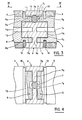
- FIG. 2 it can be seen that there has been designated by 1, as a whole, a safety barrel with double rotor, intended to cooperate with the members of the larder lock, of the conventional type, represented in FIG.
- a mortise lock of this kind can be mounted in the thickness of a door. Thanks to barrel 1 with double rotor, the door can be locked on both sides, using a flat key E.
- the stator 3 of the barrel 1 has the shape of a U between the two parallel branches 4, 5 of which is disposed a bit A.
- the two branches 4, 5 of the stator are pierced by two substantially coaxial cylindrical housings inside which can rotate two rotors B and-C having the same structure and which can both be actuated by means of the open-ended spanner E.
- each rotor B, C is provided in the conventional manner, a diametrical recess Ib, 1c allowing the introduction of the spanner flat E.
- each of the branches 4, 5 of the stator are made five parallel bores 6 arranged in a plane passing through the axis of the cylindrical housing where the rotor B, C can rotate.
- five bores 2b, 2c extending from the five bores 6, when the mean plane of the diametrical recess lb, lc passes through the axes of the bores 6; the bores 2b, 2c of the rotors B, C have a shoulder 3b, 3c and open into the thickness of the diametrical recess 1b, lc.
- each set of bores (6, 2b or 2c) are placed a rotor pin 4b, 4c, a stator pin 7, a spring 8 and a plug 9.
- the teeth of the key E have a height such that when 'it is pressed into the diametrical recess lb or lc, the contact area of the rotor pins 4b or 4c and the stator pins 7 is located at the surface of the cylindrical rotor housing.
- the two rotors B and C protrude inside the U of the stator 3; inside a peripheral groove 5b, 5c formed on their projecting part, engages a rod 10 (FIGS. 3 to 6) preventing relative movement of translation of each rotor B, C with respect to its stator branch.
- a cylindrical cavity 6b, 6c On the two adjacent end faces of the two rotors B and C is formed a cylindrical cavity 6b, 6c whose axis is coincident with the axis of the rotor.
- the hub 1a of the bit A is pivotally mounted inside the two aforementioned cylindrical cavities 6b, 6c.
- the axis of rotation of the bit A coincides with the axes of rotation of the two rotors B and C.
- the hub la two symmetrical diametrical recesses 2a each arranged in the extension of the diametrical recess 16, lc of the rotors B, C.
- the bit A comprises an outer ring 3a arranged concentrically with the hub la; the hub 1a is connected to the outer ring 3a by an annular web 4a disposed in the plane of radial symmetry of the bit A.
- an operating finger 5a (FIG. 2) is provided in relief on the outer ring 3a of the bit AT.
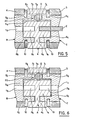
- the essential characteristic element of the double-rotor barrel according to the invention is to include an indexing mechanism making it possible to link, in rotation, the bit A to the two rotors B and C, when no key E is inserted in said rotors.
- This indexing mechanism comprises an oblong housing 20 formed between, on the one hand, the bit A and, on the other hand, the two rotors B and C.
- the longitudinal axis of the oblong housing 20 can freely move a ball D which is not subject to the action of any spring; the longitudinal axis of the oblong housing 20 is parallel to the axis of rotation common to the two rotors B, C and of the bit A.
- the cross section of the oblong housing 20, that is to say the section perpendicular to its longitudinal axis is substantially constant and equal, to the clearance close to the section of the ball D; it follows that the ball D can move inside the oblong housing 20, only along the longitudinal axis of said housing.
- the length 1 of the oblong housing 20 measured along its longitudinal axis is substantially equal at one and a half times the diameter of the ball D.
- the oblong housing 20 is produced by drilling an axial bore in the wall of the web 4a; the height of the above-mentioned axial bore, measured radially, is greater than the width of the web 4a also measured radially, so that this bore extends on either side of the web 4a by two grooves facing one towards the another, one 5a formed on the hub 1a and the other 6a formed on the inner side wall of the ring 3a.
- the central part of the oblong housing 20 is formed by the thickness of the web 4a, which is less than the diameter of the ball D but greater than half its diameter.
- Each end of the oblong housing 20 is constituted by a recess 7b, 7c, formed on the end edge of the wall of the rotor B, C which surrounds the cavity 6b, 6c where the hub la of the bit A pivots; the two recesses 7b, 7c have the same shape and dimensions; the depth of each recess 7b, 7c measured along the longitudinal axis of the oblong housing 20 is less than the radius of the ball D.
- the bit A can only rotate at an angle of a very small value and is therefore linked in rotation to the two rotors B and C, moreover locked in their respective stator branches .
- the position illustrated in FIG. 3 corresponds to the case where the bit A would be equivalent to a torque caused for example by a member of the lock: after a slight rotation of the bit A with respect to the two rotors B and C blocked in rotation, the ball D is chased in the central part of the oblong housing 20 and engages with the two rotors B and C.
- the double rotor barrel according to the invention can not only equip the mortice lock of FIG. 1, but also any other locking system such as for example a safety lock.
- the lock of FIG. 1 usually comprises a deadbolt 30 and a half-turn bolt 31; the operating finger 5a of the bit A cooperates with the end of a lever 32 whose hinge pin 33 is carried by the dead bolt 30.
- the lever 32 is linked to the tail 34 of the U-bolt 31, said U-bolt being subjected to the action of a return spring.
- the tail 34 of the U-bolt 31 is also linked to a follower 35 controlled by a door handle (not shown). Maneuvering the above-mentioned stand or a slight rotation of the bit A of the double rotor barrel 1, by means of a key E, makes it possible to cause the recal of the latch bolt 31. In a known manner, according to the direction of rotation of the bit A, the output or withdrawal of the deadbolt 30 is also obtained.
Landscapes
- Engineering & Computer Science (AREA)
- Mechanical Engineering (AREA)
- Adornments (AREA)
- Lock And Its Accessories (AREA)
Applications Claiming Priority (2)
| Application Number | Priority Date | Filing Date | Title |
|---|---|---|---|
| FR8115542A FR2511420A1 (fr) | 1981-08-11 | 1981-08-11 | Dispositif permettant d'indexer la position angulaire d'une piece a par rapport a deux pieces rotatives b et c, barillet de surete a double rotor correspondant et appareil de fermeture qui en est equipe |
| FR8115542 | 1981-08-11 |
Publications (1)
| Publication Number | Publication Date |
|---|---|
| EP0072332A1 true EP0072332A1 (fr) | 1983-02-16 |
Family
ID=9261383
Family Applications (1)
| Application Number | Title | Priority Date | Filing Date |
|---|---|---|---|
| EP82401511A Withdrawn EP0072332A1 (fr) | 1981-08-11 | 1982-08-10 | Barillet de sûreté à double rotor et appareil de fermeture qui en est équipe |
Country Status (2)
| Country | Link |
|---|---|
| EP (1) | EP0072332A1 (enExample) |
| FR (1) | FR2511420A1 (enExample) |
Cited By (3)
| Publication number | Priority date | Publication date | Assignee | Title |
|---|---|---|---|---|
| ES2205952A1 (es) * | 1999-07-27 | 2004-05-01 | Talleres De Escoriaza, S.A. | Cilindro de cerradura. |
| US7343763B2 (en) * | 2005-06-16 | 2008-03-18 | Moshe Dolev | Cylinder lock with modified cam |
| US20090031769A1 (en) * | 2006-06-14 | 2009-02-05 | Moshe Dolev | High - security rotating bolt lock |
Citations (3)
| Publication number | Priority date | Publication date | Assignee | Title |
|---|---|---|---|---|
| FR600303A (fr) * | 1924-07-03 | 1926-02-04 | Hahn Fur Optik Und Mechanik Ag | Serrure de sûreté à cylindre double |
| FR1290046A (fr) * | 1961-02-24 | 1962-04-06 | Viro S P A | Serrure à double cylindre |
| FR2080445A5 (enExample) * | 1970-02-13 | 1971-11-12 | Winkhaus Fa August |
-
1981
- 1981-08-11 FR FR8115542A patent/FR2511420A1/fr active Granted
-
1982
- 1982-08-10 EP EP82401511A patent/EP0072332A1/fr not_active Withdrawn
Patent Citations (3)
| Publication number | Priority date | Publication date | Assignee | Title |
|---|---|---|---|---|
| FR600303A (fr) * | 1924-07-03 | 1926-02-04 | Hahn Fur Optik Und Mechanik Ag | Serrure de sûreté à cylindre double |
| FR1290046A (fr) * | 1961-02-24 | 1962-04-06 | Viro S P A | Serrure à double cylindre |
| FR2080445A5 (enExample) * | 1970-02-13 | 1971-11-12 | Winkhaus Fa August |
Cited By (5)
| Publication number | Priority date | Publication date | Assignee | Title |
|---|---|---|---|---|
| ES2205952A1 (es) * | 1999-07-27 | 2004-05-01 | Talleres De Escoriaza, S.A. | Cilindro de cerradura. |
| ES2205952B1 (es) * | 1999-07-27 | 2005-04-16 | Talleres De Escoriaza, S.A. | Cilindro de cerradura. |
| US7343763B2 (en) * | 2005-06-16 | 2008-03-18 | Moshe Dolev | Cylinder lock with modified cam |
| US20090031769A1 (en) * | 2006-06-14 | 2009-02-05 | Moshe Dolev | High - security rotating bolt lock |
| US8522584B2 (en) * | 2006-06-14 | 2013-09-03 | Moshe Dolev | High-security rotating bolt lock |
Also Published As
| Publication number | Publication date |
|---|---|
| FR2511420B3 (enExample) | 1984-06-29 |
| FR2511420A1 (fr) | 1983-02-18 |
Similar Documents
| Publication | Publication Date | Title |
|---|---|---|
| FR2522053A1 (fr) | Cle a levier basculant et barillet de surete utilisant ladite cle | |
| EP0983411B1 (fr) | Cle a poussoir mobile, barillet de surete pour ladite cle et serrure equipee de ce barillet | |
| EP1291478B1 (fr) | Serrure à montage universel | |
| EP0151081B1 (fr) | Serrure à bloc de sûreté rapporté, agencée pour empêcher son ouverture frauduleuse | |
| EP0072332A1 (fr) | Barillet de sûreté à double rotor et appareil de fermeture qui en est équipe | |
| EP0700479B1 (fr) | Cle a double rampe d'extremite pour barillet de surete, barillet correspondant et ensemble constitue d'une telle cle et d'un tel barillet | |
| WO1988007615A1 (fr) | Serrure a mecanisme de verrouillage-deverrouillage a l'aide d'un electro-aimant | |
| EP0410830A1 (fr) | Serrure de sûreté à stator débrayable | |
| EP1697606B1 (fr) | Dispositif de blocage et de deblocage d'un mouvement d'actionnement, notamment pour serrure de surete, muni de moyens de blocage en cas de tronconnement du barillet | |
| FR2696776A1 (fr) | Cylindre de serrure, à clé dynamique. | |
| FR2821380A1 (fr) | Serrure de porte a pene demi-tour | |
| FR2802234A1 (fr) | Barillet de surete muni d'un moyen anti-crochetage | |
| EP0940529A1 (fr) | Cylindre de sûreté à barillet double | |
| EP0769597A1 (fr) | Verrou du type à rotor débrayable | |
| EP0869236B1 (fr) | Cylindre de sûrete manoeuvrable d'un côté quand une clef est en place de l'autre côté | |
| FR2666369A1 (fr) | Ferrure pour une fenetre, une porte, ou similaire. | |
| EP0444972A1 (fr) | Verrou comprenant un stator et un rotor monté libre en rotation dans le stator | |
| FR2815067A1 (fr) | Cylindre de surete a barillet prioritaire | |
| FR2531127A1 (fr) | Serrure a pompe equipee d'un collier mobile anti-crochetage avec delateur et piege | |
| FR2683579A1 (fr) | Agencement de verrouillage d'un organe mobile de fermeture d'une ouverture, telle qu'une porte. | |
| BE1020632A3 (fr) | Dispositif de serrure auxiliaire independante. | |
| EP0242277A1 (fr) | Serrure mobile perfectionnée à fermeture autre que par anse | |
| FR2500880A1 (fr) | Dispositif d'ouverture interieure d'une porte, notamment de chambre frigorifique | |
| EP3708747A1 (fr) | Serrure d'urgence adaptée pour être déverrouillée de l'intérieur | |
| FR2777125A1 (fr) | Dispositif de fermeture a securite, notamment pour coffret, armoire ou autre enveloppe electrique |
Legal Events
| Date | Code | Title | Description |
|---|---|---|---|
| PUAI | Public reference made under article 153(3) epc to a published international application that has entered the european phase |
Free format text: ORIGINAL CODE: 0009012 |
|
| 17P | Request for examination filed |
Effective date: 19820823 |
|
| AK | Designated contracting states |
Designated state(s): AT BE CH DE GB IT LI NL |
|
| STAA | Information on the status of an ep patent application or granted ep patent |
Free format text: STATUS: THE APPLICATION HAS BEEN WITHDRAWN |
|
| 18W | Application withdrawn |
Withdrawal date: 19841126 |
|
| RIN1 | Information on inventor provided before grant (corrected) |
Inventor name: GIRARD, JOEL Inventor name: ALLARD, YVES |