EP0071366B1 - Lampen-Betriebsschaltung - Google Patents
Lampen-Betriebsschaltung Download PDFInfo
- Publication number
- EP0071366B1 EP0071366B1 EP82303702A EP82303702A EP0071366B1 EP 0071366 B1 EP0071366 B1 EP 0071366B1 EP 82303702 A EP82303702 A EP 82303702A EP 82303702 A EP82303702 A EP 82303702A EP 0071366 B1 EP0071366 B1 EP 0071366B1
- Authority
- EP
- European Patent Office
- Prior art keywords
- circuit
- transistor
- switch means
- lamp
- rail
- Prior art date
- Legal status (The legal status is an assumption and is not a legal conclusion. Google has not performed a legal analysis and makes no representation as to the accuracy of the status listed.)
- Expired
Links
Images
Classifications
-
- H—ELECTRICITY
- H05—ELECTRIC TECHNIQUES NOT OTHERWISE PROVIDED FOR
- H05B—ELECTRIC HEATING; ELECTRIC LIGHT SOURCES NOT OTHERWISE PROVIDED FOR; CIRCUIT ARRANGEMENTS FOR ELECTRIC LIGHT SOURCES, IN GENERAL
- H05B39/00—Circuit arrangements or apparatus for operating incandescent light sources
- H05B39/02—Switching on, e.g. with predetermined rate of increase of lighting current
-
- H—ELECTRICITY
- H02—GENERATION; CONVERSION OR DISTRIBUTION OF ELECTRIC POWER
- H02J—CIRCUIT ARRANGEMENTS OR SYSTEMS FOR SUPPLYING OR DISTRIBUTING ELECTRIC POWER; SYSTEMS FOR STORING ELECTRIC ENERGY
- H02J7/00—Circuit arrangements for charging or depolarising batteries or for supplying loads from batteries
- H02J7/0029—Circuit arrangements for charging or depolarising batteries or for supplying loads from batteries with safety or protection devices or circuits
- H02J7/00304—Overcurrent protection
-
- H—ELECTRICITY
- H02—GENERATION; CONVERSION OR DISTRIBUTION OF ELECTRIC POWER
- H02J—CIRCUIT ARRANGEMENTS OR SYSTEMS FOR SUPPLYING OR DISTRIBUTING ELECTRIC POWER; SYSTEMS FOR STORING ELECTRIC ENERGY
- H02J7/00—Circuit arrangements for charging or depolarising batteries or for supplying loads from batteries
- H02J7/0029—Circuit arrangements for charging or depolarising batteries or for supplying loads from batteries with safety or protection devices or circuits
- H02J7/00308—Overvoltage protection
-
- H—ELECTRICITY
- H02—GENERATION; CONVERSION OR DISTRIBUTION OF ELECTRIC POWER
- H02J—CIRCUIT ARRANGEMENTS OR SYSTEMS FOR SUPPLYING OR DISTRIBUTING ELECTRIC POWER; SYSTEMS FOR STORING ELECTRIC ENERGY
- H02J7/00—Circuit arrangements for charging or depolarising batteries or for supplying loads from batteries
- H02J7/0047—Circuit arrangements for charging or depolarising batteries or for supplying loads from batteries with monitoring or indicating devices or circuits
-
- H—ELECTRICITY
- H02—GENERATION; CONVERSION OR DISTRIBUTION OF ELECTRIC POWER
- H02J—CIRCUIT ARRANGEMENTS OR SYSTEMS FOR SUPPLYING OR DISTRIBUTING ELECTRIC POWER; SYSTEMS FOR STORING ELECTRIC ENERGY
- H02J7/00—Circuit arrangements for charging or depolarising batteries or for supplying loads from batteries
- H02J7/14—Circuit arrangements for charging or depolarising batteries or for supplying loads from batteries for charging batteries from dynamo-electric generators driven at varying speed, e.g. on vehicle
Definitions
- This invention relates to a lamp drive circuit of the type which comprises a first supply input for connection to a first supply rail, a second supply input for connection to a second supply rail, a control input for receiving a control signal, a lamp output for connection to one side of a warning lamp, the other side of which, in use, is connected to the first supply rail, and switch means responsive to the signal at the control input and connected between the lamp output and the second supply input.
- a lamp drive circuit of the type described forms part of a motor vehicle alternator circuit, as shown, for example, in GB-A-1 217 149, it has been found that the connections to the first supply input and the warning lamp output may be accidentally reversed. This results in an excessive current being drawn by the lamp drive circuit and consequential damage.
- the lamp drive circuit may also be subjected to excessive current if the warning lamp becomes short circuited.
- a lamp drive circuit comprising a first supply input for connection to a first supply rail, a second supply input for connection to a second supply rail, a control input for receiving a control signal, a lamp output for connection to one side of a warning lamp, and switch means responsive to the signal at the control input and connected between the lamp output and the second supply input, characterised in that the circuit further comprises a current measuring resistor connected in series with the switch means between the lamp output and the second supply input, a capacitor connected between the control input and the second supply input, the voltage across the capacitor controlling the state of the switch means, and voltage sensitive means responsive to the voltage drop across the current measuring resistor and arranged to charge the capacitor in the event of the voltage drop exceeding a predetermined value thereby turning off the switch means.
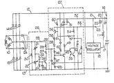
- the alternator circuit there shown comprises an alternator having a three phase armature winding 10 and a field winding 11.
- the armature winding 10 supplies current to positive and negative supply rails 12 and 13 through diodes 14 and 15.
- the positive supply rail 12 is connected through a terminal 16 to the positive pole of a vehicle battery 17, the negative pole of which is connected to earth and to the negative supply rail 13.
- the field winding 11 is connected to a voltage regulator 18 of well known construction which switches the field winding 11 on and off in accordance with the voltage appearing across the rails 12 and 13.
- the positive pole of the battery is connected through an ignition switch 19 to a rail 20, the rail 20 being connected directly to a terminal 21 and through a warning lamp 22 to a terminal 23.
- the circuit further includes a set of auxiliary diodes 24 which supply current to a rail 25, a fault detection circuit 26, and a lamp drive circuit 27.
- the fault detection circuit 26 comprises a resistor 30 connected between the rail 25 and the rail 13 and a pair of variable resistors 31, 32 connected in series between rails 25 and 13.
- the junction of resistors 31 and 32 is connected to the cathode of a zener diode 33, the anode of which is connected to rail 13 through a resistor 34 and a capacitor 35 connected in parallel.
- the anode of zener diode 33 is also connected to the base of an NPN transistor 36, the emitter of which is connected to rail 13 and the collector of which is connected through a pair of resistors 37 and 38 to the rail 25.
- the resistor 37 has a much smaller resistance value than the resistor 38.
- the output signal of the detection circuit 26 is provided at the junction of resistors 37 and 38 and this junction is connected to a rail 39.
- the rail 39 forms a control input and this rail is connected to rail 13 by a capacitor 45 and also by three resistors 46,47 and 65 connected in series.
- the junction of resistors 46 and 47 is connected to the base of an NPN transistor 48, the emitter of which is connected to rail 13.
- the collector of transistor 48 is connected through a resistor 49 to the cathodes of a pair of diodes 50, 51.
- the anode of diode 50 is connected to rail 12 and the anode of diode 41 is connected to a rail 52.
- the rail 52 is connected to terminal 21, the terminal 21 forming a first supply input for the lamp drive circuit 27.
- the rail 13 acts as the second supply input.
- the circuit 27 further includes a switch means in the form of an NPN Darlington transistor 53, the base of which is connected to the collector of transistor 48, the emitter of which is connected to rail 13 and the collector of which is connected through a current measuring resistor 54 to a rail 55.
- the rail 55 is connected to terminal 23 and terminal 23 comprises a warning lamp output for the circuit 27.
- the circuit 27 further includes a voltage sensitive means in the form of a PNP transistor 56.
- the emitter of transistor 56 is connected to rail 55, its base is connected through a resistor 57 to the junction of resistor 54 and transistor 53, and its collector is connected through a resistor 58 to the anode of a diode 59, the cathode of which is connected to rail 39.
- the base of transistor 56 is also connected through a resistor 60 to the rail 52.
- the rail 12 is connected to the cathode of a zener diode 61, the anode of which is connected through a resistor 62 to the base of transistor 48.
- a zener diode 63 In order to protect transistor 53, there is provided a zener diode 63, the anode of which is connected to rail 13 and the cathode of which is connected to rail 55.
- the collector of transistor 53 is connected to the junction of resistors 47 and 65 via a resistor 64.
- the fault detection circuit 26 supplies no current on rail 39. Consequently, capacitor 45 is discharged, transistor 48 is off, transistor 53 is on and the warning lamp 22 is energised. With the alternator 10 operating normally and producing current, capacitor 45 will be charged from rail 39 thereby turning on transistor 48, turning off transistor 53 and de-energising the warning lamp 22. In the event of armature 10 producing an excessive voltage, the voltage at the junction of resistors 31 and 32 will be sufficient to cause breakdown of zener diode 33 and thereby turning on transistor 36, discharging capacitor 45 and turning off transistor 48, and thereby turning on transistor 53 and energising the warning lamp 22. In the case of over voltage, hysteresis is provided by resistors 64 and 65 and the feedback to transistor 48.
- the transistor 56 does not sense the full voltage drop across the resistor 54 as the voltage at its base is raised by resistors 60 and 57.
- the initial current is high and this initial high current is associated with a voltage drop across the lamp 22.
- the resistors 60 and 57 are provided to take advantage of the voltage drop across the lamp 22 in order to prevent the initial high current turning on transistor 56. Their resistance values are chosen accordingly.
- zener diode 61 breaks down thereby turning on transistor 48 and turning off transistor 53 and protecting the warning lamp 22.
- the lamp drive circuit 27 may be formed entirely from discrete components.
- the transistor 53 may be a discrete component and the remainder of the circuit may be formed as an integrated circuit.
- lamp drive circuit 27 has been shown as forming part of an alternator circuit, it is to be appreciated that the lamp drive circuit 27 is suitable for any application where excessive currents may occur.
Landscapes
- Engineering & Computer Science (AREA)
- Power Engineering (AREA)
- Control Of Eletrric Generators (AREA)
- Emergency Protection Circuit Devices (AREA)
- Control Of Charge By Means Of Generators (AREA)
- Circuit Arrangement For Electric Light Sources In General (AREA)
- Lighting Device Outwards From Vehicle And Optical Signal (AREA)
Claims (6)
Applications Claiming Priority (2)
| Application Number | Priority Date | Filing Date | Title |
|---|---|---|---|
| GB8122857 | 1981-07-24 | ||
| GB8122857 | 1981-07-24 |
Publications (2)
| Publication Number | Publication Date |
|---|---|
| EP0071366A1 EP0071366A1 (de) | 1983-02-09 |
| EP0071366B1 true EP0071366B1 (de) | 1986-02-26 |
Family
ID=10523469
Family Applications (1)
| Application Number | Title | Priority Date | Filing Date |
|---|---|---|---|
| EP82303702A Expired EP0071366B1 (de) | 1981-07-24 | 1982-07-14 | Lampen-Betriebsschaltung |
Country Status (8)
| Country | Link |
|---|---|
| US (1) | US4593233A (de) |
| EP (1) | EP0071366B1 (de) |
| JP (1) | JPS58108694A (de) |
| AU (1) | AU550826B2 (de) |
| DE (2) | DE3269368D1 (de) |
| ES (1) | ES8307433A1 (de) |
| IN (1) | IN158953B (de) |
| YU (1) | YU160582A (de) |
Families Citing this family (6)
| Publication number | Priority date | Publication date | Assignee | Title |
|---|---|---|---|---|
| JPS61165997A (ja) * | 1984-12-10 | 1986-07-26 | 林原 健 | 白熱電球点燈装置 |
| JPH0412636Y2 (de) * | 1985-04-18 | 1992-03-26 | ||
| US4819116A (en) * | 1988-08-31 | 1989-04-04 | R. E. Phelon Company, Inc. | Fault indicator light control circuit |
| JP2522639Y2 (ja) * | 1989-01-09 | 1997-01-16 | 三菱電機株式会社 | 車両用交流発電機の制御装置 |
| US7069826B2 (en) * | 2004-10-08 | 2006-07-04 | Mike Tilton | Screwdriver attachment |
| JP4457312B2 (ja) * | 2006-01-12 | 2010-04-28 | 株式会社デンソー | 車両用ヘッドランプ装置 |
Family Cites Families (18)
| Publication number | Priority date | Publication date | Assignee | Title |
|---|---|---|---|---|
| US3219903A (en) * | 1962-07-16 | 1965-11-23 | Gen Motors Corp | Generating system with rectifier protection means |
| US3300702A (en) * | 1963-09-03 | 1967-01-24 | Globe Union Inc | Protection device for solid state battery charging systems |
| GB1341959A (en) * | 1970-06-17 | 1973-12-25 | Lucas Industries Ltd | Electrical systems for road vehicles |
| GB1402253A (en) * | 1971-09-17 | 1975-08-06 | Lucas Electrical Co Ltd | Lamp failure warning circuits |
| US3883777A (en) * | 1972-08-02 | 1975-05-13 | Tokai Rika Co Ltd | Device for automatically compensating failure of a lamp |
| US3956733A (en) * | 1973-04-10 | 1976-05-11 | Nippondenso Co., Ltd. | Monitoring system for an automobile light circuit |
| SU483736A1 (ru) * | 1973-07-13 | 1975-09-05 | Научно-исследовательский и экспериментальный институт автомобильного электрооборудования и автоприборов | Устроство дл защиты генераторной установки |
| US4104560A (en) * | 1974-08-21 | 1978-08-01 | Nippondenso Co., Ltd. | Lighting system for a motor vehicle |
| DE2741054A1 (de) * | 1977-03-30 | 1979-03-22 | Riba Jutta | Kontrollgeraet zur ueberwachung von gluehlampen |
| FR2416477A1 (fr) * | 1978-02-02 | 1979-08-31 | Ducellier & Cie | Dispositif de detection d'anomalies par lampe temoin pour dispositif de charge de la batterie d'accumulateurs de vehicule automobile |
| DE2811440A1 (de) * | 1978-03-16 | 1979-09-20 | Bosch Gmbh Robert | Elektrischer generator |
| FR2423790A1 (fr) * | 1978-04-19 | 1979-11-16 | Sev Marchal | Appareil de surveillance du circuit de charge de la batterie d'un vehicule automobile |
| US4189662A (en) * | 1978-05-10 | 1980-02-19 | Horng Fu Erh | Safety device for lamps of motor vehicle |
| US4218717A (en) * | 1978-08-21 | 1980-08-19 | Harry Shuster | Electric control system for motor vehicle |
| JPS55157942A (en) * | 1979-05-25 | 1980-12-09 | Nippon Denso Co | Automotive generator generation control device |
| JPS5743528A (en) * | 1980-08-29 | 1982-03-11 | Nippon Denso Co | Generation display unit for automotive generator |
| JPS5834599U (ja) * | 1981-08-31 | 1983-03-07 | 日本電気株式会社 | 保護回路 |
| US4459631A (en) * | 1982-10-28 | 1984-07-10 | General Motors Corporation | Transient over-voltage protection circuit |
-
1982
- 1982-07-09 US US06/396,559 patent/US4593233A/en not_active Expired - Fee Related
- 1982-07-14 EP EP82303702A patent/EP0071366B1/de not_active Expired
- 1982-07-14 DE DE8282303702T patent/DE3269368D1/de not_active Expired
- 1982-07-14 DE DE198282303702T patent/DE71366T1/de active Pending
- 1982-07-22 YU YU01605/82A patent/YU160582A/xx unknown
- 1982-07-22 JP JP57126852A patent/JPS58108694A/ja active Pending
- 1982-07-22 AU AU86295/82A patent/AU550826B2/en not_active Ceased
- 1982-07-22 IN IN850/CAL/82A patent/IN158953B/en unknown
- 1982-07-23 ES ES514312A patent/ES8307433A1/es not_active Expired
Also Published As
| Publication number | Publication date |
|---|---|
| AU8629582A (en) | 1983-01-27 |
| US4593233A (en) | 1986-06-03 |
| YU160582A (en) | 1985-06-30 |
| EP0071366A1 (de) | 1983-02-09 |
| ES514312A0 (es) | 1983-06-16 |
| IN158953B (de) | 1987-02-28 |
| AU550826B2 (en) | 1986-04-10 |
| JPS58108694A (ja) | 1983-06-28 |
| DE71366T1 (de) | 1983-07-21 |
| DE3269368D1 (en) | 1986-04-03 |
| ES8307433A1 (es) | 1983-06-16 |
Similar Documents
| Publication | Publication Date | Title |
|---|---|---|
| US3522481A (en) | Storage battery protective device | |
| US4658200A (en) | Protection circuit for voltage regulator of vehicle mounted generator | |
| US5376854A (en) | Device for detecting failure in piezoelectric apparatus | |
| EP0408059B1 (de) | Steuergerät für einen Fahrzeugwechselstromgenerator | |
| US5266882A (en) | Control device for an alternating current generator of a vehicle | |
| US5023539A (en) | Alternator voltage transient minimization method and apparatus | |
| US3942096A (en) | Voltage regulating system | |
| US4695915A (en) | Short circuit and overload protection circuit for output stage transistors | |
| KR20000010878A (ko) | 과전압으로부터 보호하기 위한 장치 및 방법 | |
| US4723191A (en) | Electronic voltage regulator for use in vehicles with protection against transient overvoltages | |
| US4295087A (en) | Charge indicator circuit for a battery charging system | |
| US3597654A (en) | Protective circuit for a voltage regulator | |
| US4471287A (en) | Charging generator control apparatus | |
| KR960003201B1 (ko) | 이상전압 검출 제어장치 | |
| EP0071366B1 (de) | Lampen-Betriebsschaltung | |
| US3931546A (en) | Over-voltage protection circuit | |
| US3943408A (en) | Over-voltage protection circuit for wye connected electric machine | |
| US4036199A (en) | Device for protecting an ignition device for motor vehicles | |
| US3529211A (en) | Generator protective device using a zener diode as an overvoltage sensor | |
| US3406318A (en) | Potential regulator with an electrical polarity reversal protection feature | |
| US4570199A (en) | Protection circuit for voltage regulator of vehicle mounted generator | |
| US4672297A (en) | AC generator control status detecting device with short-circuit protection means | |
| US4812732A (en) | Control device for an a. c. generator for an automobile | |
| US4755734A (en) | Voltage regulator for vehicle mounted generator | |
| US4438384A (en) | Generation indicating apparatus for vehicle alternators |
Legal Events
| Date | Code | Title | Description |
|---|---|---|---|
| PUAI | Public reference made under article 153(3) epc to a published international application that has entered the european phase |
Free format text: ORIGINAL CODE: 0009012 |
|
| AK | Designated contracting states |
Designated state(s): DE FR GB IT |
|
| ITCL | It: translation for ep claims filed |
Representative=s name: BUGNION S.P.A. |
|
| EL | Fr: translation of claims filed | ||
| DET | De: translation of patent claims | ||
| 17P | Request for examination filed |
Effective date: 19830722 |
|
| GRAA | (expected) grant |
Free format text: ORIGINAL CODE: 0009210 |
|
| ITF | It: translation for a ep patent filed |
Owner name: BUGNION S.P.A. |
|
| AK | Designated contracting states |
Designated state(s): DE FR GB IT |
|
| ET | Fr: translation filed | ||
| REF | Corresponds to: |
Ref document number: 3269368 Country of ref document: DE Date of ref document: 19860403 |
|
| PLBE | No opposition filed within time limit |
Free format text: ORIGINAL CODE: 0009261 |
|
| STAA | Information on the status of an ep patent application or granted ep patent |
Free format text: STATUS: NO OPPOSITION FILED WITHIN TIME LIMIT |
|
| 26N | No opposition filed | ||
| PG25 | Lapsed in a contracting state [announced via postgrant information from national office to epo] |
Ref country code: GB Effective date: 19890714 |
|
| PG25 | Lapsed in a contracting state [announced via postgrant information from national office to epo] |
Ref country code: FR Free format text: LAPSE BECAUSE OF NON-PAYMENT OF DUE FEES Effective date: 19900330 |
|
| PG25 | Lapsed in a contracting state [announced via postgrant information from national office to epo] |
Ref country code: DE Effective date: 19900403 |
|
| GBPC | Gb: european patent ceased through non-payment of renewal fee | ||
| REG | Reference to a national code |
Ref country code: FR Ref legal event code: ST |