EP0070921B1 - Elément incorporé pour un dispositif d'échange de matières et d'échange direct de chaleur et pour un dispositif mélangeur - Google Patents
Elément incorporé pour un dispositif d'échange de matières et d'échange direct de chaleur et pour un dispositif mélangeur Download PDFInfo
- Publication number
- EP0070921B1 EP0070921B1 EP81106949A EP81106949A EP0070921B1 EP 0070921 B1 EP0070921 B1 EP 0070921B1 EP 81106949 A EP81106949 A EP 81106949A EP 81106949 A EP81106949 A EP 81106949A EP 0070921 B1 EP0070921 B1 EP 0070921B1
- Authority
- EP
- European Patent Office
- Prior art keywords
- guide surfaces
- layer
- layers
- packing element
- guide
- Prior art date
- Legal status (The legal status is an assumption and is not a legal conclusion. Google has not performed a legal analysis and makes no representation as to the accuracy of the status listed.)
- Expired
Links
Images


Classifications
-
- B—PERFORMING OPERATIONS; TRANSPORTING
- B01—PHYSICAL OR CHEMICAL PROCESSES OR APPARATUS IN GENERAL
- B01D—SEPARATION
- B01D3/00—Distillation or related exchange processes in which liquids are contacted with gaseous media, e.g. stripping
- B01D3/14—Fractional distillation or use of a fractionation or rectification column
- B01D3/16—Fractionating columns in which vapour bubbles through liquid
- B01D3/24—Fractionating columns in which vapour bubbles through liquid with sloping plates or elements mounted stepwise
-
- B—PERFORMING OPERATIONS; TRANSPORTING
- B01—PHYSICAL OR CHEMICAL PROCESSES OR APPARATUS IN GENERAL
- B01F—MIXING, e.g. DISSOLVING, EMULSIFYING OR DISPERSING
- B01F25/00—Flow mixers; Mixers for falling materials, e.g. solid particles
- B01F25/40—Static mixers
- B01F25/42—Static mixers in which the mixing is affected by moving the components jointly in changing directions, e.g. in tubes provided with baffles or obstructions
- B01F25/43—Mixing tubes, e.g. wherein the material is moved in a radial or partly reversed direction
- B01F25/432—Mixing tubes, e.g. wherein the material is moved in a radial or partly reversed direction with means for dividing the material flow into separate sub-flows and for repositioning and recombining these sub-flows; Cross-mixing, e.g. conducting the outer layer of the material nearer to the axis of the tube or vice-versa
-
- B—PERFORMING OPERATIONS; TRANSPORTING
- B01—PHYSICAL OR CHEMICAL PROCESSES OR APPARATUS IN GENERAL
- B01J—CHEMICAL OR PHYSICAL PROCESSES, e.g. CATALYSIS OR COLLOID CHEMISTRY; THEIR RELEVANT APPARATUS
- B01J19/00—Chemical, physical or physico-chemical processes in general; Their relevant apparatus
- B01J19/32—Packing elements in the form of grids or built-up elements for forming a unit or module inside the apparatus for mass or heat transfer
-
- F—MECHANICAL ENGINEERING; LIGHTING; HEATING; WEAPONS; BLASTING
- F28—HEAT EXCHANGE IN GENERAL
- F28F—DETAILS OF HEAT-EXCHANGE AND HEAT-TRANSFER APPARATUS, OF GENERAL APPLICATION
- F28F25/00—Component parts of trickle coolers
- F28F25/02—Component parts of trickle coolers for distributing, circulating, and accumulating liquid
- F28F25/08—Splashing boards or grids, e.g. for converting liquid sprays into liquid films; Elements or beds for increasing the area of the contact surface
-
- B—PERFORMING OPERATIONS; TRANSPORTING
- B01—PHYSICAL OR CHEMICAL PROCESSES OR APPARATUS IN GENERAL
- B01J—CHEMICAL OR PHYSICAL PROCESSES, e.g. CATALYSIS OR COLLOID CHEMISTRY; THEIR RELEVANT APPARATUS
- B01J2219/00—Chemical, physical or physico-chemical processes in general; Their relevant apparatus
- B01J2219/32—Details relating to packing elements in the form of grids or built-up elements for forming a unit of module inside the apparatus for mass or heat transfer
- B01J2219/322—Basic shape of the elements
- B01J2219/32203—Sheets
- B01J2219/32206—Flat sheets
-
- B—PERFORMING OPERATIONS; TRANSPORTING
- B01—PHYSICAL OR CHEMICAL PROCESSES OR APPARATUS IN GENERAL
- B01J—CHEMICAL OR PHYSICAL PROCESSES, e.g. CATALYSIS OR COLLOID CHEMISTRY; THEIR RELEVANT APPARATUS
- B01J2219/00—Chemical, physical or physico-chemical processes in general; Their relevant apparatus
- B01J2219/32—Details relating to packing elements in the form of grids or built-up elements for forming a unit of module inside the apparatus for mass or heat transfer
- B01J2219/322—Basic shape of the elements
- B01J2219/32203—Sheets
- B01J2219/32213—Plurality of essentially parallel sheets
-
- B—PERFORMING OPERATIONS; TRANSPORTING
- B01—PHYSICAL OR CHEMICAL PROCESSES OR APPARATUS IN GENERAL
- B01J—CHEMICAL OR PHYSICAL PROCESSES, e.g. CATALYSIS OR COLLOID CHEMISTRY; THEIR RELEVANT APPARATUS
- B01J2219/00—Chemical, physical or physico-chemical processes in general; Their relevant apparatus
- B01J2219/32—Details relating to packing elements in the form of grids or built-up elements for forming a unit of module inside the apparatus for mass or heat transfer
- B01J2219/322—Basic shape of the elements
- B01J2219/32203—Sheets
- B01J2219/32224—Sheets characterised by the orientation of the sheet
- B01J2219/32234—Inclined orientation
-
- B—PERFORMING OPERATIONS; TRANSPORTING
- B01—PHYSICAL OR CHEMICAL PROCESSES OR APPARATUS IN GENERAL
- B01J—CHEMICAL OR PHYSICAL PROCESSES, e.g. CATALYSIS OR COLLOID CHEMISTRY; THEIR RELEVANT APPARATUS
- B01J2219/00—Chemical, physical or physico-chemical processes in general; Their relevant apparatus
- B01J2219/32—Details relating to packing elements in the form of grids or built-up elements for forming a unit of module inside the apparatus for mass or heat transfer
- B01J2219/322—Basic shape of the elements
- B01J2219/32286—Grids or lattices
-
- F—MECHANICAL ENGINEERING; LIGHTING; HEATING; WEAPONS; BLASTING
- F28—HEAT EXCHANGE IN GENERAL
- F28D—HEAT-EXCHANGE APPARATUS, NOT PROVIDED FOR IN ANOTHER SUBCLASS, IN WHICH THE HEAT-EXCHANGE MEDIA DO NOT COME INTO DIRECT CONTACT
- F28D21/00—Heat-exchange apparatus not covered by any of the groups F28D1/00 - F28D20/00
- F28D2021/0019—Other heat exchangers for particular applications; Heat exchange systems not otherwise provided for
- F28D2021/0052—Other heat exchangers for particular applications; Heat exchange systems not otherwise provided for for mixers
-
- Y—GENERAL TAGGING OF NEW TECHNOLOGICAL DEVELOPMENTS; GENERAL TAGGING OF CROSS-SECTIONAL TECHNOLOGIES SPANNING OVER SEVERAL SECTIONS OF THE IPC; TECHNICAL SUBJECTS COVERED BY FORMER USPC CROSS-REFERENCE ART COLLECTIONS [XRACs] AND DIGESTS
- Y10—TECHNICAL SUBJECTS COVERED BY FORMER USPC
- Y10S—TECHNICAL SUBJECTS COVERED BY FORMER USPC CROSS-REFERENCE ART COLLECTIONS [XRACs] AND DIGESTS
- Y10S261/00—Gas and liquid contact apparatus
- Y10S261/72—Packing elements
-
- Y—GENERAL TAGGING OF NEW TECHNOLOGICAL DEVELOPMENTS; GENERAL TAGGING OF CROSS-SECTIONAL TECHNOLOGIES SPANNING OVER SEVERAL SECTIONS OF THE IPC; TECHNICAL SUBJECTS COVERED BY FORMER USPC CROSS-REFERENCE ART COLLECTIONS [XRACs] AND DIGESTS
- Y10—TECHNICAL SUBJECTS COVERED BY FORMER USPC
- Y10T—TECHNICAL SUBJECTS COVERED BY FORMER US CLASSIFICATION
- Y10T428/00—Stock material or miscellaneous articles
- Y10T428/24—Structurally defined web or sheet [e.g., overall dimension, etc.]
- Y10T428/24149—Honeycomb-like
-
- Y—GENERAL TAGGING OF NEW TECHNOLOGICAL DEVELOPMENTS; GENERAL TAGGING OF CROSS-SECTIONAL TECHNOLOGIES SPANNING OVER SEVERAL SECTIONS OF THE IPC; TECHNICAL SUBJECTS COVERED BY FORMER USPC CROSS-REFERENCE ART COLLECTIONS [XRACs] AND DIGESTS
- Y10—TECHNICAL SUBJECTS COVERED BY FORMER USPC
- Y10T—TECHNICAL SUBJECTS COVERED BY FORMER US CLASSIFICATION
- Y10T428/00—Stock material or miscellaneous articles
- Y10T428/24—Structurally defined web or sheet [e.g., overall dimension, etc.]
- Y10T428/24479—Structurally defined web or sheet [e.g., overall dimension, etc.] including variation in thickness
- Y10T428/24562—Interlaminar spaces
Definitions
- the invention relates to a built-in element for a device for mass and / or direct heat exchange or mixing, which consists of several layers, wherein guide surfaces are arranged parallel to one another and connected to each other, the guide surfaces touching point-by-point and where Guiding surfaces of neighboring locations intersect.
- trickle filling for mass transfer columns.
- a trickle filling of this type should consist of trickle areas arranged next to one another in layers, with inclined guide faces being bent out of these trickle areas, which should touch the adjacent trickle areas themselves or their bent guide areas in a point-like or linear manner.
- the sliding surfaces themselves also form part of the total pouring surface, they also essentially have the function of spacers from adjacent flat pouring surfaces.
- a second embodiment of individual elements for mass transfer columns with a large number of vertical, mutually parallel trickle surfaces is known from DE-A-2 910 525.
- the parallel pouring surfaces of the known built-in element are to be held at equal distances from one another by means of rags bent out of the pouring surfaces.
- the task of the known built-in elements here is to homogeneously mix two or more substances flowing in direct current, i. H. to achieve a high-quality mixing quality of the end product across the entire flow cross-section for each quantity and viscosity ratio of the components to be mixed.
- the invention has set itself the task of a structure of a built-in element which can be produced simply and inexpensively for any desired diameter.
- the guide surfaces are connected at their ends by connecting bridges which are at an angle to the guide surfaces, the guide surfaces of adjacent layers crossing in such a way that their longitudinal edges touch each other at points.
- An advantageous production method for the installation element according to the invention is that the guide surfaces of each individual layer are formed from a film-like material by punching and bending out of the plane of the film, and that connecting bridges between the individual guide surfaces remain from the remaining material, and that Installation element is formed in such a way that at least two layers are placed next to one another in such a way that the guiding surfaces of adjacent layers intersect, installation elements of any desired cross sections being obtained by lining up layers of different lengths.
- the film-like material consists of plastic
- the layers can also be produced by injection molding, the built-in element likewise being formed in such a way that the guide surfaces of adjacent layers intersect.
- FIGS. 5-10 show sections of a second modified embodiment of a layer.
- 11-13 and 14-16 show sections of two further embodiments of a layer which are modified compared to FIGS. 8-10 and in FIGS. 17-19 compared to FIGS. 2-4.
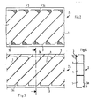
- Fig. 1 shows sections of an embodiment of three layers 2 produced according to the invention before assembly.
- 2-4 show the shapes of a layer 2 that are produced during manufacture.
- FIG. 2 shows in plan a section of a layer 2 formed from a sheet-like material, in particular sheet metal by punching.
- the layer 2 has punched-out parallel guide surfaces 1, which are optionally perforated and / or roughened or corrugated and which have a connection at each end bridge 3 are connected like a railing via triangular connecting pieces 3a.
- the guide surfaces are connected to the connecting bridges 3 at their diagonally opposite corners by means of the connecting pieces 3a.
- the hatched areas represent gaps that arise when the guide surfaces are punched out. H. the tips of the guide surfaces are cut off during punching so that they do not protrude from the layer plane when bending out.
- the guide surfaces are bent out of the plane of the connecting bridges 3 at an angle, as shown in FIG. 3 in a view and in FIG. 4 in a side view along the section line 111-111.
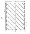
- the individual layers After the individual layers have been formed, they are placed on top of one another in such a way that the guiding surfaces of adjacent layers intersect, as indicated in FIG. 1.
- the connecting bridges touching each other, for. B. fixed by spot welding.
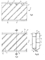
- FIGS. 5-7 show an embodiment which corresponds to FIGS. 2-4, except for the modified type of connection of the guide surfaces 1 'with the connecting bridges 3', which consists in that each guide surface per layer at the two ends a long side are connected via connecting pieces 3a 'to a connecting bridge 3'.
- the elements that correspond to FIGS. 2-4 are designated with the same reference numbers, but with an apostrophe.
- FIGS. 8-10 show an embodiment of a position in an analogous representation to FIGS. 2-4 and 5-7, in which two guide surfaces 1 are alternately bent forwards and backwards.
- FIGS. 1-7 The elements corresponding to FIGS. 1-7 are designated by the same reference numerals, but provided with ".
- the floor plan shown in FIG. 8 again shows a section of a layer 2 "with punched-out guide surfaces 1" and connecting bridges 3 ".
- the layers 3" additionally have on one long side a surface element 1a which, when bent out of the film-like material in the plane the connecting bridges 3 "remains.
- FIGS. 8 shows the bending lines 4 of the guide surfaces 1 ′′ by which the guide surfaces are bent forwards or backwards, as can be seen from FIGS.
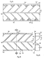
- FIGS. 8-10 show, in an analogous manner to FIGS. 8-10, a section of a layer 10 in a plan view in the punched-out state, a view in the bent-out state and a corresponding side view along the section line XII-XII.
- each guide surface consists of two sections 11a and 11b, which, analogously to FIG. 8, each have a surface element 12a or 12b on one long side, which remain when the guide surface is bent out of the film-like material in the plane of the connecting bridges 13a, 13b and 13c .
- FIGS. 11-13 show an embodiment analogous to that of FIGS. 11-13, which differs in that the sections 11a 'and 11b' of each guide surface form an angle with one another.
- FIGS. 11-13 The elements corresponding to FIGS. 11-13 are designated with the same reference numbers and provided with an apostrophe.
- FIGS. 17 and 18 show layers 2 which correspond to FIGS. 2 and 4, connection tabs 5 additionally remaining on the guide surfaces 1 and being punched out of the adjacent guide surfaces.
- the connecting straps 5 are bent in such a way that they come to lie in a plane parallel to the connecting bridges 3, so that an additional connection possibility can be created between adjacent layers 2.
- the layers are arranged parallel to the column axis.
- the guide surfaces on the edges of their narrow sides and / or the connecting bridges on their free edges are advantageously designed in a jagged manner, so that they serve for a uniform outflow of the liquid phase.
Landscapes
- Chemical & Material Sciences (AREA)
- Chemical Kinetics & Catalysis (AREA)
- Engineering & Computer Science (AREA)
- Thermal Sciences (AREA)
- Physics & Mathematics (AREA)
- Mechanical Engineering (AREA)
- Organic Chemistry (AREA)
- General Engineering & Computer Science (AREA)
- Dispersion Chemistry (AREA)
- Physical Or Chemical Processes And Apparatus (AREA)
- Gas Separation By Absorption (AREA)
- Extraction Or Liquid Replacement (AREA)
- Vaporization, Distillation, Condensation, Sublimation, And Cold Traps (AREA)
- Escalators And Moving Walkways (AREA)
- Injection Moulding Of Plastics Or The Like (AREA)
Claims (6)
Applications Claiming Priority (2)
| Application Number | Priority Date | Filing Date | Title |
|---|---|---|---|
| CH4923/81A CH656320A5 (de) | 1981-07-30 | 1981-07-30 | Einbauelement fuer eine vorrichtung fuer stoff- und/oder direkten waermeaustausch oder mischen. |
| CH4923/81 | 1981-07-30 |
Publications (2)
| Publication Number | Publication Date |
|---|---|
| EP0070921A1 EP0070921A1 (fr) | 1983-02-09 |
| EP0070921B1 true EP0070921B1 (fr) | 1986-01-02 |
Family
ID=4284875
Family Applications (1)
| Application Number | Title | Priority Date | Filing Date |
|---|---|---|---|
| EP81106949A Expired EP0070921B1 (fr) | 1981-07-30 | 1981-09-04 | Elément incorporé pour un dispositif d'échange de matières et d'échange direct de chaleur et pour un dispositif mélangeur |
Country Status (8)
| Country | Link |
|---|---|
| US (1) | US4532086A (fr) |
| EP (1) | EP0070921B1 (fr) |
| JP (1) | JPS5827635A (fr) |
| AU (1) | AU550532B2 (fr) |
| BR (1) | BR8204111A (fr) |
| CA (1) | CA1211104A (fr) |
| CH (1) | CH656320A5 (fr) |
| DE (1) | DE3173371D1 (fr) |
Families Citing this family (18)
| Publication number | Priority date | Publication date | Assignee | Title |
|---|---|---|---|---|
| CH656320A5 (de) * | 1981-07-30 | 1986-06-30 | Sulzer Ag | Einbauelement fuer eine vorrichtung fuer stoff- und/oder direkten waermeaustausch oder mischen. |
| JPS60179101A (ja) * | 1984-02-28 | 1985-09-13 | Ngk Insulators Ltd | 流体接触用多孔体 |
| GB2195327A (en) * | 1986-09-16 | 1988-04-07 | Tuke & Bell Ltd | Fluid processing medium |
| US4806288A (en) * | 1987-09-23 | 1989-02-21 | Nowosinski George B | Packing elements |
| US4882130A (en) * | 1988-06-07 | 1989-11-21 | Ngk Insulators, Ltd. | Porous structure of fluid contact |
| CH676434A5 (en) * | 1988-09-14 | 1991-01-31 | Sulzer Ag | Corrugations in sheet filling elements for fluid contact - columns are bonded at numerous meeting points to resist displacement |
| DE3920123C1 (fr) * | 1989-06-20 | 1990-12-20 | Alfred Innsbruck At Hupfauf | |
| US5326504A (en) * | 1993-08-16 | 1994-07-05 | The Boc Group, Inc. | Ordered packing |
| US5458817A (en) * | 1994-04-19 | 1995-10-17 | Lantec Products, Inc. | Folding packing and method of manufacture |
| US5637263A (en) * | 1994-04-19 | 1997-06-10 | Lantec Products, Inc. | Multifold packing and method of forming |
| IT1274171B (it) * | 1994-05-06 | 1997-07-15 | Bruno Neri | Corpo scambiatore di calore modulare per raffreddamento evaporativo diliquidi a geometria variabile ed impilabile per il trasporto |
| FR2738574B1 (fr) * | 1995-09-12 | 1997-11-21 | Total Raffinage Distribution | Procede et dispositif d'extraction des composes aromatiques contenus dans une charge d'hydrocarbures |
| FR2741279B1 (fr) | 1995-11-17 | 2001-06-15 | Inst Francais Du Petrole | Bloc de garnissage a pouvoir eleve d'adsorption pour dispositif d'epuration d'effluents gazeux |
| US6032932A (en) * | 1998-01-27 | 2000-03-07 | Sixsmith; Richard | Packing grates for wet gas scrubber and other applications |
| US6958463B1 (en) * | 2004-04-23 | 2005-10-25 | Thermosoft International Corporation | Heater with simultaneous hot spot and mechanical intrusion protection |
| US8235361B2 (en) * | 2009-02-09 | 2012-08-07 | Tribute Creations, Llc | Structured packing for a reactor |
| US9677828B2 (en) * | 2014-06-05 | 2017-06-13 | Zoneflow Reactor Technologies, Llp | Engineered packing for heat exchange and systems and methods constructing the same |
| KR101687578B1 (ko) | 2016-04-29 | 2017-01-02 | 이석룡 | 수평형 습식 스크러버의 충전물용 그레이팅 |
Citations (1)
| Publication number | Priority date | Publication date | Assignee | Title |
|---|---|---|---|---|
| DE2942481A1 (de) * | 1979-10-20 | 1981-04-30 | Bayer Ag, 5090 Leverkusen | Rieselfuellung fuer stoffaustauschkolonnen |
Family Cites Families (15)
| Publication number | Priority date | Publication date | Assignee | Title |
|---|---|---|---|---|
| US1561044A (en) * | 1925-02-20 | 1925-11-10 | Clive M Alexander | Baffle tower |
| US3168432A (en) * | 1961-12-22 | 1965-02-02 | Thore M Elfving | Core material |
| SE328597B (fr) * | 1968-04-04 | 1970-09-21 | C Munters | |
| US3574103A (en) * | 1968-09-06 | 1971-04-06 | Atomic Energy Commission | Laminated cellular material form |
| DE2019081A1 (de) * | 1970-04-21 | 1971-11-11 | Kabel Metallwerke Ghh | Thermisch isoliertes Leitungsrohr |
| CH537208A (de) * | 1971-04-29 | 1973-07-13 | Sulzer Ag | Mischeinrichtung für fliessfähige Medien |
| US3801419A (en) * | 1971-07-20 | 1974-04-02 | Munters Ab Carl | Corrugated sheet member with a reinforcing edge extending lengthwise of the corrugations |
| US3758372A (en) * | 1971-07-22 | 1973-09-11 | Fmc Corp | Foraminous structures |
| CH578371A5 (fr) * | 1973-05-23 | 1976-08-13 | Sulzer Ag | |
| JPS5651996Y2 (fr) * | 1975-04-02 | 1981-12-04 | ||
| CH619202A5 (fr) * | 1976-06-17 | 1980-09-15 | Sulzer Ag | |
| US4107241A (en) * | 1976-10-12 | 1978-08-15 | Raschig G.M.B.H. | Contacting arrangement for mass transfer operations |
| DE2910525C2 (de) * | 1979-03-17 | 1983-07-14 | Julius Montz Gmbh, 4010 Hilden | Austauschkolonnenpackung |
| CH656320A5 (de) * | 1981-07-30 | 1986-06-30 | Sulzer Ag | Einbauelement fuer eine vorrichtung fuer stoff- und/oder direkten waermeaustausch oder mischen. |
| EP0070915A1 (fr) * | 1981-07-30 | 1983-02-09 | GebràDer Sulzer Aktiengesellschaft | Elément incorporé pour un dispositif d'échange de matières et d'échange direct de chaleur et pour un dispositif mélangeur |
-
1981
- 1981-07-30 CH CH4923/81A patent/CH656320A5/de not_active IP Right Cessation
- 1981-09-04 EP EP81106949A patent/EP0070921B1/fr not_active Expired
- 1981-09-04 DE DE8181106949T patent/DE3173371D1/de not_active Expired
-
1982
- 1982-07-12 US US06/397,435 patent/US4532086A/en not_active Expired - Lifetime
- 1982-07-12 JP JP57121109A patent/JPS5827635A/ja active Granted
- 1982-07-15 BR BR8204111A patent/BR8204111A/pt not_active IP Right Cessation
- 1982-07-23 CA CA000407990A patent/CA1211104A/fr not_active Expired
- 1982-07-28 AU AU86492/82A patent/AU550532B2/en not_active Ceased
Patent Citations (1)
| Publication number | Priority date | Publication date | Assignee | Title |
|---|---|---|---|---|
| DE2942481A1 (de) * | 1979-10-20 | 1981-04-30 | Bayer Ag, 5090 Leverkusen | Rieselfuellung fuer stoffaustauschkolonnen |
Also Published As
| Publication number | Publication date |
|---|---|
| AU8649282A (en) | 1983-02-03 |
| CH656320A5 (de) | 1986-06-30 |
| EP0070921A1 (fr) | 1983-02-09 |
| JPH0372341B2 (fr) | 1991-11-18 |
| CA1211104A (fr) | 1986-09-09 |
| DE3173371D1 (en) | 1986-02-13 |
| US4532086A (en) | 1985-07-30 |
| BR8204111A (pt) | 1983-07-05 |
| JPS5827635A (ja) | 1983-02-18 |
| AU550532B2 (en) | 1986-03-27 |
Similar Documents
| Publication | Publication Date | Title |
|---|---|---|
| EP0070921B1 (fr) | Elément incorporé pour un dispositif d'échange de matières et d'échange direct de chaleur et pour un dispositif mélangeur | |
| EP0072875B1 (fr) | Elément incorporé pour un dispositif d'échange de matières et d'échange direct de chaleur et pour un dispositif mélangeur | |
| EP0070916B1 (fr) | Elément incorporé pour un dispositif à enveloppe tubulaire pour échange de matières et échange direct de chaleur et mélange | |
| EP0070915A1 (fr) | Elément incorporé pour un dispositif d'échange de matières et d'échange direct de chaleur et pour un dispositif mélangeur | |
| EP0526392B1 (fr) | Immixtion de petites quantités de fluides | |
| DE3622316C1 (de) | Plattenwaermeaustauscher | |
| EP0070917B1 (fr) | Colonne pour procédés d'échange de matière et/ou de chaleur | |
| EP1216747B1 (fr) | Mélangeur statique | |
| WO1996030113A1 (fr) | Dispositif de melange de petites quantites de liquides | |
| EP0764462B1 (fr) | Elément de garnissage, en particulier pour colonnes ou tours d'échange de matière et/ou de chaleur | |
| DE2205371B2 (de) | Vorrichtung mit einem Mantelrohr, in das ein oder mehrere Einbauelemente, die aus mehreren parallel zur Achse des Mantelrohres liegenden, sich berührenden ebenen Lagen bestehen | |
| DE2320741A1 (de) | Statische mischeinrichtung | |
| DE2322683A1 (de) | Einbauelement zur fluessigkeitsfuehrung in fluessigkeits/gas-kontaktgeraeten | |
| EP0231841B1 (fr) | Dispositif pour la distribution uniforme d'un liquide contenant des matières solides sur une section transversale | |
| DE1911471B2 (de) | Anordnung in einem Wärmetauscher ; mit in einem Rahmen gestapelten Platten | |
| DE3221130C2 (fr) | ||
| DE3020564A1 (de) | Verfahren zur herstellung einer fluid-kontakt-vorrichtung | |
| DE4020735C2 (fr) | ||
| DE2516078C3 (de) | Systematisch aufgebaute Packung für Stoffaustauschkolonnen | |
| DE2806557A1 (de) | Bausystem | |
| DE10063248A1 (de) | Kommutatorausbildungsplatte, Verfahren zur Herstellung und Motor damit | |
| DE2622530A1 (de) | Mischvorrichtung | |
| DE2933593C2 (de) | Vorrichtung zum Aufstreuen von Spänen auf eine Streuunterlage | |
| DE2712702C2 (de) | Vorrichtung zur Festlegung von Einbauplatten in Berieselungseinbauten von Wärmetauschern | |
| DE2902668A1 (de) | Magnetische zeichenanordnung und verfahren zu deren verwendung |
Legal Events
| Date | Code | Title | Description |
|---|---|---|---|
| PUAI | Public reference made under article 153(3) epc to a published international application that has entered the european phase |
Free format text: ORIGINAL CODE: 0009012 |
|
| 17P | Request for examination filed |
Effective date: 19810904 |
|
| AK | Designated contracting states |
Designated state(s): AT BE CH DE FR GB IT LI LU NL SE |
|
| RBV | Designated contracting states (corrected) |
Designated state(s): DE FR GB IT NL SE |
|
| ITF | It: translation for a ep patent filed |
Owner name: ING. ZINI MARANESI & C. S.R.L. |
|
| GRAA | (expected) grant |
Free format text: ORIGINAL CODE: 0009210 |
|
| AK | Designated contracting states |
Designated state(s): DE FR GB IT NL SE |
|
| ET | Fr: translation filed | ||
| REF | Corresponds to: |
Ref document number: 3173371 Country of ref document: DE Date of ref document: 19860213 |
|
| PLBE | No opposition filed within time limit |
Free format text: ORIGINAL CODE: 0009261 |
|
| STAA | Information on the status of an ep patent application or granted ep patent |
Free format text: STATUS: NO OPPOSITION FILED WITHIN TIME LIMIT |
|
| 26N | No opposition filed | ||
| ITTA | It: last paid annual fee | ||
| PGFP | Annual fee paid to national office [announced via postgrant information from national office to epo] |
Ref country code: SE Payment date: 19940822 Year of fee payment: 14 |
|
| PGFP | Annual fee paid to national office [announced via postgrant information from national office to epo] |
Ref country code: NL Payment date: 19940930 Year of fee payment: 14 |
|
| EAL | Se: european patent in force in sweden |
Ref document number: 81106949.1 |
|
| PG25 | Lapsed in a contracting state [announced via postgrant information from national office to epo] |
Ref country code: SE Effective date: 19950905 |
|
| PG25 | Lapsed in a contracting state [announced via postgrant information from national office to epo] |
Ref country code: NL Effective date: 19960401 |
|
| NLV4 | Nl: lapsed or anulled due to non-payment of the annual fee |
Effective date: 19960401 |
|
| EUG | Se: european patent has lapsed |
Ref document number: 81106949.1 |
|
| PGFP | Annual fee paid to national office [announced via postgrant information from national office to epo] |
Ref country code: GB Payment date: 19970811 Year of fee payment: 17 |
|
| PGFP | Annual fee paid to national office [announced via postgrant information from national office to epo] |
Ref country code: FR Payment date: 19970820 Year of fee payment: 17 |
|
| PGFP | Annual fee paid to national office [announced via postgrant information from national office to epo] |
Ref country code: DE Payment date: 19970821 Year of fee payment: 17 |
|
| PG25 | Lapsed in a contracting state [announced via postgrant information from national office to epo] |
Ref country code: GB Free format text: LAPSE BECAUSE OF NON-PAYMENT OF DUE FEES Effective date: 19980904 |
|
| GBPC | Gb: european patent ceased through non-payment of renewal fee |
Effective date: 19980904 |
|
| PG25 | Lapsed in a contracting state [announced via postgrant information from national office to epo] |
Ref country code: FR Free format text: LAPSE BECAUSE OF NON-PAYMENT OF DUE FEES Effective date: 19990531 |
|
| REG | Reference to a national code |
Ref country code: FR Ref legal event code: ST |
|
| PG25 | Lapsed in a contracting state [announced via postgrant information from national office to epo] |
Ref country code: DE Free format text: LAPSE BECAUSE OF NON-PAYMENT OF DUE FEES Effective date: 19990803 |