EP0070917B1 - Colonne pour procédés d'échange de matière et/ou de chaleur - Google Patents
Colonne pour procédés d'échange de matière et/ou de chaleur Download PDFInfo
- Publication number
- EP0070917B1 EP0070917B1 EP81106618A EP81106618A EP0070917B1 EP 0070917 B1 EP0070917 B1 EP 0070917B1 EP 81106618 A EP81106618 A EP 81106618A EP 81106618 A EP81106618 A EP 81106618A EP 0070917 B1 EP0070917 B1 EP 0070917B1
- Authority
- EP
- European Patent Office
- Prior art keywords
- guide surfaces
- column
- layers
- column according
- liquid
- Prior art date
- Legal status (The legal status is an assumption and is not a legal conclusion. Google has not performed a legal analysis and makes no representation as to the accuracy of the status listed.)
- Expired
Links
- 238000000034 method Methods 0.000 title claims description 6
- 238000012546 transfer Methods 0.000 claims description 8
- 238000010276 construction Methods 0.000 claims 1
- 239000007788 liquid Substances 0.000 description 17
- 239000007791 liquid phase Substances 0.000 description 8
- 238000009434 installation Methods 0.000 description 6
- 238000012856 packing Methods 0.000 description 5
- 239000012071 phase Substances 0.000 description 4
- 238000009792 diffusion process Methods 0.000 description 3
- 239000007789 gas Substances 0.000 description 3
- 230000003068 static effect Effects 0.000 description 3
- 238000010521 absorption reaction Methods 0.000 description 2
- 230000015572 biosynthetic process Effects 0.000 description 2
- 230000000694 effects Effects 0.000 description 2
- 238000000605 extraction Methods 0.000 description 2
- 239000007792 gaseous phase Substances 0.000 description 2
- 239000002245 particle Substances 0.000 description 2
- 230000001133 acceleration Effects 0.000 description 1
- 238000013461 design Methods 0.000 description 1
- 238000011161 development Methods 0.000 description 1
- 230000018109 developmental process Effects 0.000 description 1
- 239000012530 fluid Substances 0.000 description 1
- 230000005484 gravity Effects 0.000 description 1
- 230000007704 transition Effects 0.000 description 1
- 238000003466 welding Methods 0.000 description 1
Images

Classifications
-
- B—PERFORMING OPERATIONS; TRANSPORTING
- B01—PHYSICAL OR CHEMICAL PROCESSES OR APPARATUS IN GENERAL
- B01D—SEPARATION
- B01D3/00—Distillation or related exchange processes in which liquids are contacted with gaseous media, e.g. stripping
- B01D3/14—Fractional distillation or use of a fractionation or rectification column
- B01D3/16—Fractionating columns in which vapour bubbles through liquid
- B01D3/24—Fractionating columns in which vapour bubbles through liquid with sloping plates or elements mounted stepwise
-
- B—PERFORMING OPERATIONS; TRANSPORTING
- B01—PHYSICAL OR CHEMICAL PROCESSES OR APPARATUS IN GENERAL
- B01F—MIXING, e.g. DISSOLVING, EMULSIFYING OR DISPERSING
- B01F25/00—Flow mixers; Mixers for falling materials, e.g. solid particles
- B01F25/40—Static mixers
- B01F25/42—Static mixers in which the mixing is affected by moving the components jointly in changing directions, e.g. in tubes provided with baffles or obstructions
- B01F25/43—Mixing tubes, e.g. wherein the material is moved in a radial or partly reversed direction
- B01F25/431—Straight mixing tubes with baffles or obstructions that do not cause substantial pressure drop; Baffles therefor
- B01F25/4316—Straight mixing tubes with baffles or obstructions that do not cause substantial pressure drop; Baffles therefor the baffles being flat pieces of material, e.g. intermeshing, fixed to the wall or fixed on a central rod
-
- B—PERFORMING OPERATIONS; TRANSPORTING
- B01—PHYSICAL OR CHEMICAL PROCESSES OR APPARATUS IN GENERAL
- B01J—CHEMICAL OR PHYSICAL PROCESSES, e.g. CATALYSIS OR COLLOID CHEMISTRY; THEIR RELEVANT APPARATUS
- B01J19/00—Chemical, physical or physico-chemical processes in general; Their relevant apparatus
- B01J19/32—Packing elements in the form of grids or built-up elements for forming a unit or module inside the apparatus for mass or heat transfer
-
- F—MECHANICAL ENGINEERING; LIGHTING; HEATING; WEAPONS; BLASTING
- F28—HEAT EXCHANGE IN GENERAL
- F28F—DETAILS OF HEAT-EXCHANGE AND HEAT-TRANSFER APPARATUS, OF GENERAL APPLICATION
- F28F25/00—Component parts of trickle coolers
- F28F25/02—Component parts of trickle coolers for distributing, circulating, and accumulating liquid
- F28F25/08—Splashing boards or grids, e.g. for converting liquid sprays into liquid films; Elements or beds for increasing the area of the contact surface
- F28F25/082—Spaced elongated bars, laths; Supports therefor
-
- B—PERFORMING OPERATIONS; TRANSPORTING
- B01—PHYSICAL OR CHEMICAL PROCESSES OR APPARATUS IN GENERAL
- B01J—CHEMICAL OR PHYSICAL PROCESSES, e.g. CATALYSIS OR COLLOID CHEMISTRY; THEIR RELEVANT APPARATUS
- B01J2219/00—Chemical, physical or physico-chemical processes in general; Their relevant apparatus
- B01J2219/32—Details relating to packing elements in the form of grids or built-up elements for forming a unit of module inside the apparatus for mass or heat transfer
- B01J2219/322—Basic shape of the elements
- B01J2219/32286—Grids or lattices
-
- F—MECHANICAL ENGINEERING; LIGHTING; HEATING; WEAPONS; BLASTING
- F28—HEAT EXCHANGE IN GENERAL
- F28D—HEAT-EXCHANGE APPARATUS, NOT PROVIDED FOR IN ANOTHER SUBCLASS, IN WHICH THE HEAT-EXCHANGE MEDIA DO NOT COME INTO DIRECT CONTACT
- F28D21/00—Heat-exchange apparatus not covered by any of the groups F28D1/00 - F28D20/00
- F28D2021/0019—Other heat exchangers for particular applications; Heat exchange systems not otherwise provided for
- F28D2021/0052—Other heat exchangers for particular applications; Heat exchange systems not otherwise provided for for mixers
-
- Y—GENERAL TAGGING OF NEW TECHNOLOGICAL DEVELOPMENTS; GENERAL TAGGING OF CROSS-SECTIONAL TECHNOLOGIES SPANNING OVER SEVERAL SECTIONS OF THE IPC; TECHNICAL SUBJECTS COVERED BY FORMER USPC CROSS-REFERENCE ART COLLECTIONS [XRACs] AND DIGESTS
- Y10—TECHNICAL SUBJECTS COVERED BY FORMER USPC
- Y10S—TECHNICAL SUBJECTS COVERED BY FORMER USPC CROSS-REFERENCE ART COLLECTIONS [XRACs] AND DIGESTS
- Y10S261/00—Gas and liquid contact apparatus
- Y10S261/72—Packing elements
-
- Y—GENERAL TAGGING OF NEW TECHNOLOGICAL DEVELOPMENTS; GENERAL TAGGING OF CROSS-SECTIONAL TECHNOLOGIES SPANNING OVER SEVERAL SECTIONS OF THE IPC; TECHNICAL SUBJECTS COVERED BY FORMER USPC CROSS-REFERENCE ART COLLECTIONS [XRACs] AND DIGESTS
- Y10—TECHNICAL SUBJECTS COVERED BY FORMER USPC
- Y10T—TECHNICAL SUBJECTS COVERED BY FORMER US CLASSIFICATION
- Y10T428/00—Stock material or miscellaneous articles
- Y10T428/24—Structurally defined web or sheet [e.g., overall dimension, etc.]
- Y10T428/24149—Honeycomb-like
-
- Y—GENERAL TAGGING OF NEW TECHNOLOGICAL DEVELOPMENTS; GENERAL TAGGING OF CROSS-SECTIONAL TECHNOLOGIES SPANNING OVER SEVERAL SECTIONS OF THE IPC; TECHNICAL SUBJECTS COVERED BY FORMER USPC CROSS-REFERENCE ART COLLECTIONS [XRACs] AND DIGESTS
- Y10—TECHNICAL SUBJECTS COVERED BY FORMER USPC
- Y10T—TECHNICAL SUBJECTS COVERED BY FORMER US CLASSIFICATION
- Y10T428/00—Stock material or miscellaneous articles
- Y10T428/24—Structurally defined web or sheet [e.g., overall dimension, etc.]
- Y10T428/24628—Nonplanar uniform thickness material
- Y10T428/24669—Aligned or parallel nonplanarities
- Y10T428/24686—Pleats or otherwise parallel adjacent folds
Definitions
- the invention relates to a column for mass and / or heat exchange processes in countercurrent, wherein in the exchange part of the column at least one built-in element is arranged to fill the cross-section, which consists of layers arranged parallel to the jacket tube axis, each layer having flow channels inclined to the jacket tube axis and the layers being joined together in this way that the flow channels intersect from neighboring layers.
- a column with such built-in elements is known from CH-A-398503.
- the individual layers serve as support surfaces for the liquid phase trickling down as a film under the influence of gravity, which with the gas phase filling the gaps of the installation element in countercurrent to this liquid phase, e.g. B. when applied to rectification or absorption columns or a second liquid phase when used on extraction columns in surface contact.
- a static mixing device which consists of a number of contacting layers. These layers consist of continuous plates arranged parallel to the longitudinal axis of the device, guide surfaces being arranged on both sides of these plates in such a way that intersecting channels are formed between adjacent plates.
- Such static mixing devices are penetrated by the media to be mixed in cocurrent, the surfaces of the plates and guide surfaces not forming trickling surfaces, but the open flow cross section of the mixing device being filled by the media to be mixed.
- static mixing devices are known for example from DE-B-2328795 and DE-B-2522106.
- the individual layers are to consist of parallel, continuous, essentially rectangular guide surfaces, the guide surfaces of adjacent layers intersecting. These structures, which are enclosed by a jacket tube, are penetrated by the media to be mixed in cocurrent during operation. The free flow cross-section is also filled by the media and the guide surfaces do not form trickling surfaces for a liquid phase.
- the invention has set itself the goal of achieving an improved and accelerated mass transfer and a concentration compensation over the column cross section in countercurrent columns with a built-in element.
- the individual layers consist of spaced, parallel and essentially rectangular guide surfaces, the guide surfaces of two adjacent layers crossing each other and forming open, intersecting flow channels on both sides.
- the inclined arrangement of the guide surfaces achieves very good lateral mixing of the liquid by trickling the liquid along the guide surfaces.
- the measures according to the invention significantly accelerate and improve the mass transfer and, in the case of heat transfer, the heat exchange. There is also the advantage of a low pressure drop.
- the fact that the guide surfaces of the built-in element are provided with perforations enables an increased mixing of the flowing down liquid flows on the upper and lower sides of the guide surfaces.
- Another possibility of liquid transfer from one guide surface to the adjacent one can be brought about by a jagged design of the longitudinal edges and ends of the guide surfaces.
- the liquid does not only pass at the contact points of the guide surfaces, but also by dripping from the edges of one guide surface onto the neighboring ones , underlying guiding surfaces.
- This drop formation causes an additional enlargement of the exchange surface between the two phases.
- the drops hitting a guide surface cause an additional disturbance of the trickle film located on this surface, which promotes the exchange processes.
- Additional acceleration or deceleration effects of the liquid film can be achieved by structuring the guide surfaces section by section or by steps.
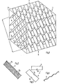
- FIG. 1 shows a perspective representation of an embodiment of a packing body designed according to the invention
- FIGS. 2 to 7 show detailed representations of guide surface sections.
- the packing body is intended for installation in a mass transfer column, for example a rectification column with a square cross section.
- the cross section can also have a different shape, e.g. B. circular if the column is circular cylindrical.
- the packing body in its edge zones is adapted to the inner jacket of the column.
- the packing body 1 consists of layers 2 of parallel guide surfaces 3, the guide surfaces of adjacent layers touching and crossing.
- the intersecting guide surfaces 3 of two adjacent layers 2 each form open, intersecting flow channels 4.
- the contour of the installation element 1 is indicated schematically by the lines U.
- the surfaces of the guide surfaces 3 can be provided with a corrugation 3a, as can be seen from FIG. 2.
- This corrugation can also be herringbone-like.
- a perforation 3b is also shown in this figure.
- the guide surfaces 3 can be provided with groove-shaped recesses 3c at their crossing points. When pushing together in the direction of the arrow, the webs overlap.
- the guiding surfaces of the individual layers can be connected to one another at their crossing points, for example by welding.
- FIGS. 5 and 6 show a top view and a view of an exemplary embodiment with teeth 6 on the side edges of a guide surface 3.
- FIG. 7 there is an embodiment shown with a serrated formation 5 of the lower end of a guide surface 3.
- the built-in element can be made of several parts that are assembled within the column to form a whole built-in element.
Landscapes
- Chemical & Material Sciences (AREA)
- Chemical Kinetics & Catalysis (AREA)
- Engineering & Computer Science (AREA)
- Thermal Sciences (AREA)
- Physics & Mathematics (AREA)
- Mechanical Engineering (AREA)
- Organic Chemistry (AREA)
- General Engineering & Computer Science (AREA)
- Dispersion Chemistry (AREA)
- Physical Or Chemical Processes And Apparatus (AREA)
- Vaporization, Distillation, Condensation, Sublimation, And Cold Traps (AREA)
- Extraction Or Liquid Replacement (AREA)
- Gas Separation By Absorption (AREA)
Claims (7)
Applications Claiming Priority (2)
| Application Number | Priority Date | Filing Date | Title |
|---|---|---|---|
| CH4922/81A CH653909A5 (de) | 1981-07-30 | 1981-07-30 | Kolonne fuer stoff- und/oder waermeaustauschverfahren. |
| CH4922/81 | 1981-07-30 |
Publications (2)
| Publication Number | Publication Date |
|---|---|
| EP0070917A1 EP0070917A1 (fr) | 1983-02-09 |
| EP0070917B1 true EP0070917B1 (fr) | 1985-11-06 |
Family
ID=4284857
Family Applications (1)
| Application Number | Title | Priority Date | Filing Date |
|---|---|---|---|
| EP81106618A Expired EP0070917B1 (fr) | 1981-07-30 | 1981-08-26 | Colonne pour procédés d'échange de matière et/ou de chaleur |
Country Status (8)
| Country | Link |
|---|---|
| US (1) | US4744928A (fr) |
| EP (1) | EP0070917B1 (fr) |
| JP (1) | JPS5830332A (fr) |
| AU (1) | AU561435B2 (fr) |
| BR (1) | BR8203968A (fr) |
| CA (1) | CA1211367A (fr) |
| CH (1) | CH653909A5 (fr) |
| DE (1) | DE3172836D1 (fr) |
Cited By (2)
| Publication number | Priority date | Publication date | Assignee | Title |
|---|---|---|---|---|
| DE29601936U1 (de) * | 1996-02-08 | 1996-04-18 | Preussag Anlagenbau | Statischer Mischer |
| EP2380660A1 (fr) | 2010-04-20 | 2011-10-26 | Sulzer Chemtech AG | Colonne d'échange de matière et élément de jante pour une colonne d'échange de matière |
Families Citing this family (36)
| Publication number | Priority date | Publication date | Assignee | Title |
|---|---|---|---|---|
| DE3735923A1 (de) * | 1987-10-23 | 1989-06-01 | Linde Ag | Einbauelement fuer eine stoff- und waermeaustauschkolonne |
| BR8901120A (pt) * | 1988-03-17 | 1989-10-31 | Union Carbide Corp | Elemento de enchimento de coluna;processo para a pratica de transferencia de massa entre vapor e liquido |
| US4865460A (en) * | 1988-05-02 | 1989-09-12 | Kama Corporation | Static mixing device |
| USRE34255E (en) * | 1988-05-02 | 1993-05-18 | Krup Corporation | Static mixing device |
| DE3920123C1 (fr) * | 1989-06-20 | 1990-12-20 | Alfred Innsbruck At Hupfauf | |
| ES2072403T3 (es) * | 1990-03-30 | 1995-07-16 | Koch Eng Co Inc | Estructura y metodo para la reaccion catalitica de chorros de fluido en un aparato de transferencia de masa. |
| EP0503990B1 (fr) * | 1991-03-08 | 1994-06-01 | Institut Français du Pétrole | Appareil de distillation-réaction et son utilisation |
| EP0522920B1 (fr) * | 1991-07-09 | 1997-11-26 | Institut Français du Pétrole | Dispositif de distillation-réaction et son utilisation pour la réalisation de réactions équilibrées |
| ATE130220T1 (de) * | 1991-07-30 | 1995-12-15 | Sulzer Chemtech Ag | Einmischvorrichtung kleiner fluidmengen. |
| US5348710A (en) * | 1993-06-11 | 1994-09-20 | Johnson Kenneth H | Catalytic distillation structure |
| US5326504A (en) * | 1993-08-16 | 1994-07-05 | The Boc Group, Inc. | Ordered packing |
| DE59308587D1 (de) * | 1993-08-26 | 1998-06-25 | Sulzer Chemtech Ag | Packung mit katalytischen oder adsorbierenden Mitteln |
| KR960005783B1 (ko) * | 1994-01-18 | 1996-05-01 | 임인찬 | 공기 관통식 충전판 |
| US5431890A (en) * | 1994-01-31 | 1995-07-11 | Chemical Research & Licensing Company | Catalytic distillation structure |
| DE4428813C2 (de) * | 1994-08-13 | 1996-11-14 | Ewald Schwing Verfahrenstechni | Vorrichtung zum statischen Mischen von Fluiden, insbesondere von thermoplastifiziertem Kunststoff, und Verfahren zur Herstellung einer solchen Vorrichtung |
| US5484203A (en) * | 1994-10-07 | 1996-01-16 | Komax Systems Inc. | Mixing device |
| FR2741279B1 (fr) | 1995-11-17 | 2001-06-15 | Inst Francais Du Petrole | Bloc de garnissage a pouvoir eleve d'adsorption pour dispositif d'epuration d'effluents gazeux |
| US5942456A (en) * | 1996-12-09 | 1999-08-24 | Catalytic Distillation Technologies | Multi-functional catalytic distillation structure |
| US6000685A (en) * | 1998-06-29 | 1999-12-14 | Catalytic Distillation Technologies | Gas/liquid contact structure |
| ES2237070T3 (es) | 1998-11-30 | 2005-07-16 | Sulzer Chemtech Ag | Columna a contracorriente con distribuidor de liquido. |
| EP1005889B1 (fr) * | 1998-11-30 | 2005-03-30 | Sulzer Chemtech AG | Distributeur de liquide pour des colonnes garnies |
| DE59911838D1 (de) | 1998-11-30 | 2005-05-04 | Sulzer Chemtech Ag Winterthur | Flüssigkeitsverteiler für Packungskolonnen |
| DK1170054T3 (da) * | 2000-06-19 | 2003-06-23 | Balcke Duerr Gmbh | Blandemaskine til blanding af gasser og andre newtonske væsker |
| US6467949B1 (en) * | 2000-08-02 | 2002-10-22 | Chemineer, Inc. | Static mixer element and method for mixing two fluids |
| US6550960B2 (en) * | 2000-10-11 | 2003-04-22 | The Procter & Gamble Company | Apparatus for in-line mixing and process of making such apparatus |
| DE10063485A1 (de) * | 2000-12-20 | 2002-07-04 | Bayer Ag | Statischer Mischer |
| DE10159818A1 (de) * | 2001-12-06 | 2003-07-10 | Basf Ag | Geordnete Packung für einen Reaktor |
| FR2892644B1 (fr) * | 2005-10-28 | 2008-02-08 | Snecma Propulsion Solide Sa | Structure de garnissage pour colonne d'echange de fluides |
| CN102527175B (zh) * | 2010-12-16 | 2014-04-30 | 中国石油化工股份有限公司 | 一种除尘器 |
| CN102423630B (zh) * | 2011-08-30 | 2012-10-03 | 湖南麓南脱硫脱硝科技有限公司 | 用于选择性催化还原脱硝系统的静态混合器 |
| CN103143214B (zh) * | 2011-12-06 | 2015-09-23 | 中国石油化工股份有限公司 | 一种除尘器 |
| US9162206B2 (en) * | 2013-12-05 | 2015-10-20 | Exxonmobil Research And Engineering Company | Reactor bed component for securing rigid assemblies |
| US10913044B2 (en) * | 2017-07-14 | 2021-02-09 | Technip Process Technology, Inc. | Device for gas solids fluidized system to enhance stripping |
| FR3070876B1 (fr) * | 2017-09-12 | 2022-04-29 | Axens | Element de garnissage structure forme par une plaque plane munie d'encoches et d'evidements |
| US10150054B1 (en) * | 2017-11-30 | 2018-12-11 | Technip Process Technology, Inc. | Multi directional device for vapor-solid mixing |
| CN111135598B (zh) * | 2020-01-11 | 2021-06-15 | 无锡市华诚石化设备有限责任公司 | 多降液管塔盘的降液缓冲装置 |
Family Cites Families (18)
| Publication number | Priority date | Publication date | Assignee | Title |
|---|---|---|---|---|
| US1887704A (en) * | 1927-03-19 | 1932-11-15 | Wilisch Hugo | Filling block for heat exchange, reaction, and absorption apparatus |
| GB622706A (en) * | 1947-02-21 | 1949-05-05 | Olaf George Dixon | Improvements in and relating to the treatment of liquids with gases or vapours |
| US2911204A (en) * | 1955-08-17 | 1959-11-03 | Dolphus D Malone | Tower packing block |
| JPS416358Y1 (fr) * | 1965-04-08 | 1966-03-31 | ||
| US3378239A (en) * | 1966-06-13 | 1968-04-16 | Baltimore Aircoil Co Inc | Counterflow cooling tower |
| US3491892A (en) * | 1968-04-15 | 1970-01-27 | Neptune Microflo Inc | Multichannel device for liquid treatment |
| US3669425A (en) * | 1970-07-30 | 1972-06-13 | P T & T Ind Inc | Water cooling tower |
| CH537208A (de) * | 1971-04-29 | 1973-07-13 | Sulzer Ag | Mischeinrichtung für fliessfähige Medien |
| FR2223071A1 (en) * | 1973-02-12 | 1974-10-25 | Politechnika Lodzka | Mass transfer column packing of sheet matl. - vertically slitted and corrugated to give high transfer efficiency |
| CH563802A5 (fr) * | 1973-04-18 | 1975-07-15 | Sulzer Ag | |
| JPS5034284U (fr) * | 1973-07-24 | 1975-04-12 | ||
| CH578369A5 (fr) * | 1974-05-10 | 1976-08-13 | Sulzer Ag | |
| JPS5651996Y2 (fr) * | 1975-04-02 | 1981-12-04 | ||
| CH595516A5 (fr) * | 1975-07-23 | 1978-02-15 | Sulzer Ag | |
| CH615113A5 (fr) * | 1976-04-29 | 1980-01-15 | Sulzer Ag | |
| US4218408A (en) * | 1976-05-03 | 1980-08-19 | Balcke-Durr Aktiengesellschaft | Cooling tower with ripple plates |
| CH618006A5 (fr) * | 1977-05-12 | 1980-06-30 | Sulzer Ag | |
| DE2810648A1 (de) * | 1978-03-11 | 1979-09-13 | Basf Ag | Statischer mischer fuer fluide stoffe |
-
1981
- 1981-07-30 CH CH4922/81A patent/CH653909A5/de not_active IP Right Cessation
- 1981-08-26 DE DE8181106618T patent/DE3172836D1/de not_active Expired
- 1981-08-26 EP EP81106618A patent/EP0070917B1/fr not_active Expired
-
1982
- 1982-07-06 JP JP57117650A patent/JPS5830332A/ja active Granted
- 1982-07-08 BR BR8203968A patent/BR8203968A/pt not_active IP Right Cessation
- 1982-07-13 US US06/397,776 patent/US4744928A/en not_active Expired - Fee Related
- 1982-07-28 AU AU86491/82A patent/AU561435B2/en not_active Ceased
- 1982-07-29 CA CA000408384A patent/CA1211367A/fr not_active Expired
Cited By (2)
| Publication number | Priority date | Publication date | Assignee | Title |
|---|---|---|---|---|
| DE29601936U1 (de) * | 1996-02-08 | 1996-04-18 | Preussag Anlagenbau | Statischer Mischer |
| EP2380660A1 (fr) | 2010-04-20 | 2011-10-26 | Sulzer Chemtech AG | Colonne d'échange de matière et élément de jante pour une colonne d'échange de matière |
Also Published As
| Publication number | Publication date |
|---|---|
| JPS5830332A (ja) | 1983-02-22 |
| JPH0375216B2 (fr) | 1991-11-29 |
| CH653909A5 (de) | 1986-01-31 |
| EP0070917A1 (fr) | 1983-02-09 |
| AU561435B2 (en) | 1987-05-07 |
| BR8203968A (pt) | 1983-06-28 |
| AU8649182A (en) | 1983-02-03 |
| DE3172836D1 (en) | 1985-12-12 |
| US4744928A (en) | 1988-05-17 |
| CA1211367A (fr) | 1986-09-16 |
Similar Documents
| Publication | Publication Date | Title |
|---|---|---|
| EP0070917B1 (fr) | Colonne pour procédés d'échange de matière et/ou de chaleur | |
| EP0070916B1 (fr) | Elément incorporé pour un dispositif à enveloppe tubulaire pour échange de matières et échange direct de chaleur et mélange | |
| EP0070915A1 (fr) | Elément incorporé pour un dispositif d'échange de matières et d'échange direct de chaleur et pour un dispositif mélangeur | |
| EP0151693B1 (fr) | Colonne d'échange de matière | |
| DE2601890C3 (de) | Packungskörper für Stoffaustauschkolonnen | |
| DE2320741C2 (de) | Statische Mischvorrichtung | |
| EP0072875A1 (fr) | Elément incorporé pour un dispositif d'échange de matières et d'échange direct de chaleur et pour un dispositif mélangeur | |
| CH618006A5 (fr) | ||
| DE1444368A1 (de) | Stoffaustauschkolonne | |
| EP0070920A1 (fr) | Colonne pour échange de matière et pour échange directe de chaleur | |
| EP0069241A1 (fr) | Garniture pour colonnes d'échange de matières et procédé de fabrication de la garniture | |
| DE3221130C2 (fr) | ||
| EP0070921B1 (fr) | Elément incorporé pour un dispositif d'échange de matières et d'échange direct de chaleur et pour un dispositif mélangeur | |
| EP0231841A1 (fr) | Dispositif pour la distribution uniforme d'un liquide contenant des matières solides sur une section transversale | |
| DE3020564A1 (de) | Verfahren zur herstellung einer fluid-kontakt-vorrichtung | |
| DD293639A5 (de) | Rieseleinbauelement | |
| DE2516078C3 (de) | Systematisch aufgebaute Packung für Stoffaustauschkolonnen | |
| DE2555814C2 (de) | Flammrohrwand | |
| DE1442884A1 (de) | Stoffaustauschkolonne | |
| DE2702512C2 (de) | Flüssigkeits-Flüssigkeits-Kontaktboden | |
| DE1904144B2 (de) | Vorrichtung zum inkontaktbringen von gasen mit fluessigkeiten | |
| EP0038913A1 (fr) | Elément de remplissage pour échanger la chaleur de matières | |
| DE2534445A1 (de) | Gegenstromwaermeaustauscher | |
| DE1444367A1 (de) | Stoffaustauschkolonne | |
| DD205076A1 (de) | Kontaktiereinrichtung zum kontinuierlichen statischen mischen und verteilen fliessfaehiger stoffe |
Legal Events
| Date | Code | Title | Description |
|---|---|---|---|
| PUAI | Public reference made under article 153(3) epc to a published international application that has entered the european phase |
Free format text: ORIGINAL CODE: 0009012 |
|
| 17P | Request for examination filed |
Effective date: 19810826 |
|
| AK | Designated contracting states |
Designated state(s): DE FR GB IT NL SE |
|
| RBV | Designated contracting states (corrected) |
Designated state(s): DE FR GB IT NL SE |
|
| R17P | Request for examination filed (corrected) |
Effective date: 19810826 |
|
| ITF | It: translation for a ep patent filed |
Owner name: ING. ZINI MARANESI & C. S.R.L. |
|
| GRAA | (expected) grant |
Free format text: ORIGINAL CODE: 0009210 |
|
| AK | Designated contracting states |
Designated state(s): DE FR GB IT NL SE |
|
| REF | Corresponds to: |
Ref document number: 3172836 Country of ref document: DE Date of ref document: 19851212 |
|
| ET | Fr: translation filed | ||
| PLBE | No opposition filed within time limit |
Free format text: ORIGINAL CODE: 0009261 |
|
| STAA | Information on the status of an ep patent application or granted ep patent |
Free format text: STATUS: NO OPPOSITION FILED WITHIN TIME LIMIT |
|
| 26N | No opposition filed | ||
| ITTA | It: last paid annual fee | ||
| PGFP | Annual fee paid to national office [announced via postgrant information from national office to epo] |
Ref country code: SE Payment date: 19940831 Year of fee payment: 14 Ref country code: NL Payment date: 19940831 Year of fee payment: 14 |
|
| EAL | Se: european patent in force in sweden |
Ref document number: 81106618.2 |
|
| PG25 | Lapsed in a contracting state [announced via postgrant information from national office to epo] |
Ref country code: SE Effective date: 19950827 |
|
| PG25 | Lapsed in a contracting state [announced via postgrant information from national office to epo] |
Ref country code: NL Effective date: 19960301 |
|
| NLV4 | Nl: lapsed or anulled due to non-payment of the annual fee |
Effective date: 19960301 |
|
| EUG | Se: european patent has lapsed |
Ref document number: 81106618.2 |
|
| PGFP | Annual fee paid to national office [announced via postgrant information from national office to epo] |
Ref country code: GB Payment date: 19970716 Year of fee payment: 17 |
|
| PGFP | Annual fee paid to national office [announced via postgrant information from national office to epo] |
Ref country code: FR Payment date: 19970717 Year of fee payment: 17 |
|
| PGFP | Annual fee paid to national office [announced via postgrant information from national office to epo] |
Ref country code: DE Payment date: 19970804 Year of fee payment: 17 |
|
| PG25 | Lapsed in a contracting state [announced via postgrant information from national office to epo] |
Ref country code: GB Free format text: LAPSE BECAUSE OF NON-PAYMENT OF DUE FEES Effective date: 19980826 |
|
| GBPC | Gb: european patent ceased through non-payment of renewal fee |
Effective date: 19980826 |
|
| PG25 | Lapsed in a contracting state [announced via postgrant information from national office to epo] |
Ref country code: FR Free format text: LAPSE BECAUSE OF NON-PAYMENT OF DUE FEES Effective date: 19990430 |
|
| REG | Reference to a national code |
Ref country code: FR Ref legal event code: ST |
|
| PG25 | Lapsed in a contracting state [announced via postgrant information from national office to epo] |
Ref country code: DE Free format text: LAPSE BECAUSE OF NON-PAYMENT OF DUE FEES Effective date: 19990701 |