EP0066958B1 - Endometrial sampling device - Google Patents
Endometrial sampling device Download PDFInfo
- Publication number
- EP0066958B1 EP0066958B1 EP82302396A EP82302396A EP0066958B1 EP 0066958 B1 EP0066958 B1 EP 0066958B1 EP 82302396 A EP82302396 A EP 82302396A EP 82302396 A EP82302396 A EP 82302396A EP 0066958 B1 EP0066958 B1 EP 0066958B1
- Authority
- EP
- European Patent Office
- Prior art keywords
- probe
- groove
- sidewalls
- grooves
- handle
- Prior art date
- Legal status (The legal status is an assumption and is not a legal conclusion. Google has not performed a legal analysis and makes no representation as to the accuracy of the status listed.)
- Expired
Links
- 230000002357 endometrial effect Effects 0.000 title claims description 19
- 238000005070 sampling Methods 0.000 title claims description 13
- 239000000523 sample Substances 0.000 claims description 130
- 210000004291 uterus Anatomy 0.000 claims description 27
- 238000007790 scraping Methods 0.000 claims description 17
- 230000002093 peripheral effect Effects 0.000 claims description 12
- 230000001154 acute effect Effects 0.000 claims description 8
- 239000007787 solid Substances 0.000 claims description 5
- 229920002457 flexible plastic Polymers 0.000 claims description 3
- 239000000463 material Substances 0.000 description 23
- 238000003780 insertion Methods 0.000 description 7
- 230000037431 insertion Effects 0.000 description 7
- 238000000034 method Methods 0.000 description 7
- 239000007788 liquid Substances 0.000 description 6
- 238000012360 testing method Methods 0.000 description 6
- 239000004743 Polypropylene Substances 0.000 description 4
- 210000003679 cervix uteri Anatomy 0.000 description 4
- -1 polypropylene Polymers 0.000 description 4
- 229920001155 polypropylene Polymers 0.000 description 4
- 230000002159 abnormal effect Effects 0.000 description 2
- 210000003484 anatomy Anatomy 0.000 description 2
- 210000004696 endometrium Anatomy 0.000 description 2
- 210000003101 oviduct Anatomy 0.000 description 2
- 238000009595 pap smear Methods 0.000 description 2
- 206010003694 Atrophy Diseases 0.000 description 1
- 206010014733 Endometrial cancer Diseases 0.000 description 1
- 206010014759 Endometrial neoplasm Diseases 0.000 description 1
- 206010028980 Neoplasm Diseases 0.000 description 1
- 208000002495 Uterine Neoplasms Diseases 0.000 description 1
- 230000037444 atrophy Effects 0.000 description 1
- 201000011510 cancer Diseases 0.000 description 1
- 238000010276 construction Methods 0.000 description 1
- 230000002380 cytological effect Effects 0.000 description 1
- 239000011521 glass Substances 0.000 description 1
- 210000000056 organ Anatomy 0.000 description 1
- 239000004033 plastic Substances 0.000 description 1
- 229920003023 plastic Polymers 0.000 description 1
- 229920000098 polyolefin Polymers 0.000 description 1
- 206010046766 uterine cancer Diseases 0.000 description 1
- 210000001215 vagina Anatomy 0.000 description 1
Images
Classifications
-
- A—HUMAN NECESSITIES
- A61—MEDICAL OR VETERINARY SCIENCE; HYGIENE
- A61B—DIAGNOSIS; SURGERY; IDENTIFICATION
- A61B10/00—Instruments for taking body samples for diagnostic purposes; Other methods or instruments for diagnosis, e.g. for vaccination diagnosis, sex determination or ovulation-period determination; Throat striking implements
- A61B10/02—Instruments for taking cell samples or for biopsy
- A61B10/0291—Instruments for taking cell samples or for biopsy for uterus
Definitions
- This invention relates generally to medical sampling devices and more particularly to an endometrial sampling device for collecting endometrial sample material for clinical analysis.
- Sampling devices are used routinely in testing for uterine cancer.
- a wooden paddle may be inserted into the vagina to a point near the opening to the cervix and then removed with a sample of cells and other matter remaining on the paddle. The sample is then subjected to cytological analysis.
- endometrial cancer may be present in the upper regions of the uterus, it may go undetected even though a Pap test is performed.
- the present invention aims to provide an improved endometrial sampling device which is economical to make, simple to use, capable of obtaining a desirable amount of sampling material from the endometrium, allows easy insertion, allows the easy removal of the sample material from the device for test purposes, reduces the chance of damage to the patient as well as reducing discomfort, and which substantially avoids or reduces one or more of the-problems of the prior art devices.
- an endometrial sampling device comprises a specimen collection probe of solid cross-section and a handle characterised in that the probe has a groove extending transversely of the probe and adjacent the distal end thereof, the groove having scraping edges formed by the peripheral surface of the probe and the sidewalls of the groove, the sidewalls intersecting the peripheral surface at an acute angle and overhanging the groove.
- the groove extends generally normal to the longitudinal axis of the probe.
- the groove has a bottom wall and axially spaced opposed proximal and distal sidewalls and each of the sidewalls intersects the outer periphery of the probe to provide a sharp scraping edge which extends circumferentially in a smoothly curving configuration.
- the side and bottom walls of the groove connect to form an arcuate surface.
- the radius of a circle including said arcuate surface is of greater length than the distance between the centre of said circle and the outer peripheral surface of the probe.
- the scraping edges extend peripherally for at least 0.5 mm, preferably for greater than 1 mm and more preferably for greater than 1.5 mm.
- the probe may be made of flexible plastic material e.g. polypropylene, which is solid in cross-section and preferably generally circular in cross-section substantially throughout its length and preferably of substantially constant diameter throughout its length.
- flexible plastic material e.g. polypropylene, which is solid in cross-section and preferably generally circular in cross-section substantially throughout its length and preferably of substantially constant diameter throughout its length.
- the probe has at least one groove on each of the opposite sides thereof extending normal to the longitudinal axis of the probe, each of the grooves having a bottom wall and axially spaced, opposed proximal and distal sidewalls, each of the distal sidewalls intersecting the outer periphery of the probe at an acute angle to provide a sharp scraping edge at the periphery of the probe.
- the axial width of the mouth of a groove measured along the longitudinal axis of the probe is less than the axial maximum dimension of the groove measured along the longitudinal axis of the probe.
- the outer diameter of the probe is less than 6 mm.
- the handle of the device desirably includes means for indicating by feel the orientation of the probe relative to the handle when the probe is in the uterus of a patient and also means for indicating by feel the orientation of the grooves relative to the handle.
- each of the grooves is adjacent or even at the longitudinal axis of the probe.
- the longitudinal axis of the probe is substantially tangential to the arcuate surface.
- each groove at the longitudinal centre of the groove define an arcuate surface which extends for more than 180°.
- Each of the grooves is preferably open at both of the opposite ends thereof.
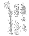
- FIG. 1 there is shown for illustration an endometrial sampler or specimen collecting device 10 having a handle 12 and an endometrial sampling collector probe or scraper 14 integrally connected to handle 12, and with the probe 14 inserted in the uterus 16 of a patient.
- the probe 14 is formed of a suitable plastic such as a moulded polyolefin, preferably polypropylene.
- a suitable plastic such as a moulded polyolefin, preferably polypropylene.
- handle 12 and probe 14 are moulded as a single part.
- Probe 14 is an elongate rod circular in cross-section and solid throughout its length. It is preferably formed or moulded with a bend as at 18 so that the distal portion of the probe is at an angle to the longitudinal axis of the handle. With this shape, the probe 14 more nearly conforms to the general anatomy making insertion and retraction from the uterus easier and with less discomfort to the patient. Since the anatomy varies with the patient, the preliminary examination can indicate how to pre-bend the probe 14 for easier insertion. When formed of polypropylene, the probe 14 will tend to retain the shape into which it is bent.
- the distal end portion 20 of probe 14 is provided with a plurality of specimen collecting grooves 22. As shown, there are four axially spaced grooves 22, although more or less grooves may be used. Two of the grooves 22 are shown on one side of probe 14 and the other two grooves are showri on the diametrically opposite side of the probe.
- the distal end or tip 23 of the probe is rounded or semi-spherical for safe, easy insertion.
- each groove 22 extends transversely across the probe 14, that is, the longitudinal axis of the groove is normal to the longitudinal axis of the probe.
- Each groove 22, as seen in Fig. 5, has axially spaced facing, opposed distal and proximal sidewalls 24 and 26, respectively, which are interconnected with a bottom wall 28.
- the walls 24 and 26 intersect the outer peripheral surface of the probe at an acute angle ⁇ to provide sharp distal and proximal edges 30 and 32, respectively, at the periphery of the probe and mouth of the groove.
- the angle ⁇ is indicated between a line 34 which is in the plane of the surface of sidewall 30 at the point of intersection with the periphery of the probe, and a line 36 which is parallel with the longitudinal axis of the probe and is at the peripheral surface of the probe. As seen in Fig. 4, line 36 crosses the centre of groove 22.
- Each of the grooves 22 in the illustrated embodiment are arcuate in cross-section (Fig. 5) and extends for more than 180° with the line 34 tangent to the arcuate surface of the sidewall 30 at the intersection with the periphery of the probe or line 36. Also, the longitudinal axis of the probe indicated at 37, is tangent to the arcuate surfaces of the grooves.
- the grooves 22 are shaped to provide facing overhang portions or hooks indicated at 38 and 40 which have the sharp edges 30 and 32, respectively, for scraping purposes.
- the edges 30 and 32 do not extend radially beyond the periphery of the probe but rather are formed at the intersection of the peripheral surface of the probe and the groove sidewalls 24 and 26.
- the opposite ends of each of the grooves 22 are open and this facilitates removal of the collected endometrial sample material from the grooves onto a slide or specimen plate, as will be discussed hereafter.
- the sharp edges 30 and 32 are rounded or generally arcuate, and are closest to each other, at their centres which are along peripheral line 36. Each sharp edge smoothly curves, with respect to the probe, circumferentially and axially away from its centre. The distal edge 30 curves distally from its centre while the edge 32 curves proximally from its centre. Since the overhanging portions 38 and 40 with their edges 30 and 32 extend circumferentially, they aid in holding collected sample material in the grooves.
- the shape of the groove provides a good receptacle for collected material so that a substantial amount can be extracted from a patient.
- the handle 12 as shown in Figs. 1 and 6, includes upper and lower horizontal plates 42 and 44 and a central vertical plate 46 integrally connected to the upper and lower plates to provide finger recesses 48 and 50. Also, the handle 12 is provided with one or more bumps 52 on the upper horizontal plate 42. When held by the hand or fingers, the recesses 48 and 50, and bumps 52, provide an indication by feel of the orientation of the probe and grooves during insertion and while the probe 14 is in the patient. These feel indicators on the handle 12 facilitate insertion and retraction of the probe 14 during the taking of samples from the uterus and tend to reduce discomfort to the patient since the probe orientation relative to the uterus is known by the person taking the specimen.
- an initial pelvic examination may be desirable to determine the size, position and configuration of the uterus of the patient from which endometrial scrapings or sample of tissue or cells is to be obtained.
- the probe 14 may then be bent, if necessary, to more nearly conform in shape to the shape that would cause the least discomfort to the patient.
- the tip 23 of the probe 14 of sampler 10 is inserted through the cervical os 56, and where desired, with a probing action so as not to scrape the cervical walls indicated at 58, on entry of the probe.
- the handle 12 may then be moved inwardly of the patient until the stop member 54 engages the os.
- the probe 14 is fully within the uterus 16 with the distal portion 20 within the body 59 of the uterus, and, preferably, in the orientation illustrated in Fig. 1.
- the upper two grooves 22 face the upper lateral side of the uterus while the two lower grooves 22 face the lower lateral side of the uterus, as seen in Fig. 1.
- the handle recesses 46 and 48 and bumps 52 will aid in inserting and maintaining the probe in a desired orientation.
- a mild pressure may be applied to handle 12 in order to urge the probe 14 and scraping edges 30 and 32 of portions 38 and 40 of the upper two grooves 22 against the upper lateral side of the endometrial surface 60 of the body 59 of the uterus.
- the probe is moved linearly outwardly and inwardly (direction of arrow heads in Fig. 1) of the uterus.
- three two-centimetre strokes may be performed so as to gently scrape the upper lateral portion of endometrial surface 60 to cause specimen material such as tissue and cells to be scraped by groove edges 30 and 32 into the upper two grooves 22.
- the probe 14 may be linearly moved, for example, three two-centimetre strokes.
- the lower lateral surface will be scraped with a result that an endometrial sample including tissue and cells will enter the lower grooves 22.
- the probe may then be retracted from the uterus while maintaining the probe in a desired orientation.
- scraping edges 30 and 32 do not extend outwardly beyond the periphery of the probe and are rounded as opposed to being pointed, they do not cause damage or undue discomfort to the patient during linear movement of the probe in gathering the endometrial sample material.
- the probe 14 preferably with the longitudinal axis of the grooves 22 on one side of the probe parallel to the surface of the glass slide onto which the specimen material or sample is to be spread, is moved across or arcuately across the slide.
- the opposite ends of each groove 22 being open, the specimen material from those grooves readily moves in a direction normal to the longitudinal axis of the probe from the grooves to the plate where the material may be readily spread.
- the second plate where desired, may be used to remove and spread the specimens from the grooves on the opposite side of the probe. In this way, the sample to be tested can be independently obtained from the upper and lower lateral sides of the body of the uterus.
- the material on the slides may then be treated and subjected to clinical testing in any suitable or conventional manner.
- the stop member 54 may be formed where desired at an angle to the handle axis, that is, with the lower end, as viewed in Fig. 1, slightly distally of the upper end. With the stop member 54 tilted in such a manner, the pressures applied to the os may be evenly distributed on insertion of the sampler.
- each groove 22 intersect the peripheral surface of probe 14 at an andle of 90° except where the sidewalls intersect the periphery at an acute angle to form the sharp scraping edges 30 and 32.
- a “sharp" edge means an edge formed by surfaces which intersect at an acute angIe ⁇ as opposed to an edge formed by surfaces that intersect an angle of 90° or greater.
- the peripheral or arc length of each of the sharp scraping edges 30 and 32 of each groove 22 or arcuate distance between the ends of each sharp edge is indicated in Figs. 3 and 4 by the peripheral or arcuate distance X.
- the distance X should be greater than 0.5 millimetre (mm) and is preferably greater than 1 mm.
- the overhanging portion 38 with edge 30 will tend to maintain material in the groove during retractile or proximal movement of the probe 14, while the overhanging portion 40 with edge 32 will tend to hold material in the groove during distal movement of the probe.
- Each of the sharp scraping edges of each groove 22 smoothly extends peripherally or circumferentially, that is, the edge does not form any point.
- the width or outer diameter of the probe 14 It is desirable to make the width or outer diameter of the probe 14 as small as possible in order to reduce discomfort during use. This is especially important in obtaining specimens from generally higher cancer risk, older females where some organ atrophy has taken place.
- the width or diameter of probe 14 must be large enough to provide a transverse groove 22 of sufficient size that it will hold enough sample material upon removal of the probe from the patient in order that desired clinical tests are possible.
- the probe 14 should have a width or outer diameter greater than 1 mm and preferably in the range of 1.5 to 6 mm.
- a preferred diameter for the probe is about 2.5 mm and with a groove or grooves 22 having a depth of about one-half that of the outer diameter of the probe.
- Polypropylene provides a strong, flexible probe which can be provided with grooves such as shown in 22 in the drawing and still be strong enough to ensure against breaking.
- an endometrial sampler made in accordance with the present invention, had a probe length from tip 23 to the stop 54 of approximately 9 centimetres.
- the probe 14 was made straight but at an angle of about 17° from the longitudinal axis of handle 12.
- the diameter of the probe was about 2.4 millimetres.
- the probe 14 has a substantially constant width or outer diameter throughout its length.
- Each of the edges had an arcuate length of about 1.8 mm. While the probe is preferably circular in cross-section other shapes, for example, oval may be used.
- the probe 14 may be moulded by employing mould pins circular in cross-section to form the arcuate grooves 22.
- Such round mould pins are highly desirable since they have the least tendency to stick or to wear unevenly.
- the grooves may be formed to have other shapes.
- the opposed proximal and distal sidewalls (24, 26) and bottom wall (28) could be made flat or of other shapes if desired, although arcuate grooves are preferred.
Landscapes
- Health & Medical Sciences (AREA)
- Life Sciences & Earth Sciences (AREA)
- Medical Informatics (AREA)
- Molecular Biology (AREA)
- Reproductive Health (AREA)
- Engineering & Computer Science (AREA)
- Biomedical Technology (AREA)
- Heart & Thoracic Surgery (AREA)
- Gynecology & Obstetrics (AREA)
- Pathology (AREA)
- Surgery (AREA)
- Animal Behavior & Ethology (AREA)
- General Health & Medical Sciences (AREA)
- Public Health (AREA)
- Veterinary Medicine (AREA)
- Sampling And Sample Adjustment (AREA)
Applications Claiming Priority (2)
| Application Number | Priority Date | Filing Date | Title |
|---|---|---|---|
| US265763 | 1981-05-21 | ||
| US06/265,763 US4441509A (en) | 1981-05-21 | 1981-05-21 | Endometrial sampling device |
Publications (3)
| Publication Number | Publication Date |
|---|---|
| EP0066958A2 EP0066958A2 (en) | 1982-12-15 |
| EP0066958A3 EP0066958A3 (en) | 1983-07-06 |
| EP0066958B1 true EP0066958B1 (en) | 1986-05-28 |
Family
ID=23011800
Family Applications (1)
| Application Number | Title | Priority Date | Filing Date |
|---|---|---|---|
| EP82302396A Expired EP0066958B1 (en) | 1981-05-21 | 1982-05-11 | Endometrial sampling device |
Country Status (6)
| Country | Link |
|---|---|
| US (1) | US4441509A (enExample) |
| EP (1) | EP0066958B1 (enExample) |
| JP (1) | JPS5832752A (enExample) |
| AU (1) | AU549474B2 (enExample) |
| CA (1) | CA1174134A (enExample) |
| DE (1) | DE3271340D1 (enExample) |
Families Citing this family (37)
| Publication number | Priority date | Publication date | Assignee | Title |
|---|---|---|---|---|
| DE3330370C2 (de) * | 1982-09-08 | 1986-03-13 | Clare Bernadette Modell | Ärztliches Instrument zur Entnahme von Proben aus der Gebärmutter |
| US4757826A (en) * | 1985-05-01 | 1988-07-19 | Gazi Abdulhay | Endocervical biopsy instrument |
| JPH0783747B2 (ja) * | 1985-09-27 | 1995-09-13 | ハロルド・ジエイ・コサスキ− | 子宮頸粘液等の試料採取器具 |
| US4711250A (en) * | 1986-09-09 | 1987-12-08 | Gilbaugh Jr James H | Hand-held medical syringe actuator device |
| US4768952A (en) * | 1986-12-03 | 1988-09-06 | Bernard Loewenthal | Dental probe |
| US4886454A (en) * | 1987-05-12 | 1989-12-12 | Bernard Loewenthal | Dental probe |
| US4887613A (en) * | 1987-11-23 | 1989-12-19 | Interventional Technologies Inc. | Cutter for atherectomy device |
| US4942788A (en) * | 1987-11-23 | 1990-07-24 | Interventional Technologies, Inc. | Method of manufacturing a cutter for atherectomy device |
| US5084005A (en) * | 1988-07-13 | 1992-01-28 | Becton, Dickinson And Company | Swab for collection of biological samples |
| US4950277A (en) * | 1989-01-23 | 1990-08-21 | Interventional Technologies, Inc. | Atherectomy cutting device with eccentric wire and method |
| US4966604A (en) * | 1989-01-23 | 1990-10-30 | Interventional Technologies Inc. | Expandable atherectomy cutter with flexibly bowed blades |
| US4986807A (en) * | 1989-01-23 | 1991-01-22 | Interventional Technologies, Inc. | Atherectomy cutter with radially projecting blade |
| JPH0399891A (ja) * | 1989-09-14 | 1991-04-25 | Ricoh Co Ltd | 用紙後処理装置 |
| US5019088A (en) * | 1989-11-07 | 1991-05-28 | Interventional Technologies Inc. | Ovoid atherectomy cutter |
| US5199441A (en) * | 1991-08-20 | 1993-04-06 | Hogle Hugh H | Fine needle aspiration biopsy apparatus and method |
| US5320110A (en) * | 1991-10-29 | 1994-06-14 | Wang Ko P | Pleural biopsy syringe-needles |
| US5224949A (en) * | 1992-01-13 | 1993-07-06 | Interventional Technologies, Inc. | Camming device |
| US5192291A (en) * | 1992-01-13 | 1993-03-09 | Interventional Technologies, Inc. | Rotationally expandable atherectomy cutter assembly |
| US5176693A (en) * | 1992-05-11 | 1993-01-05 | Interventional Technologies, Inc. | Balloon expandable atherectomy cutter |
| US5425376A (en) * | 1993-09-08 | 1995-06-20 | Sofamor Danek Properties, Inc. | Method and apparatus for obtaining a biopsy sample |
| US5766195A (en) * | 1994-03-18 | 1998-06-16 | Cordis Innovasive Systems, Inc. | Optical shunt cutter system |
| US5873852A (en) * | 1995-07-10 | 1999-02-23 | Interventional Technologies | Device for injecting fluid into a wall of a blood vessel |
| US5746716A (en) * | 1995-07-10 | 1998-05-05 | Interventional Technologies Inc. | Catheter for injecting fluid medication into an arterial wall |
| US6102904A (en) * | 1995-07-10 | 2000-08-15 | Interventional Technologies, Inc. | Device for injecting fluid into a wall of a blood vessel |
| US6706026B1 (en) | 1996-08-09 | 2004-03-16 | Cook Urological Incorporated | Instillation uterine catheter |
| US5800450A (en) * | 1996-10-03 | 1998-09-01 | Interventional Technologies Inc. | Neovascularization catheter |
| US6117153A (en) | 1996-10-03 | 2000-09-12 | Interventional Technologies, Inc. | Neovascularization catheter |
| WO2000012008A1 (en) * | 1998-08-26 | 2000-03-09 | Parlanca Limited | A sampling device |
| US6210392B1 (en) | 1999-01-15 | 2001-04-03 | Interventional Technologies, Inc. | Method for treating a wall of a blood vessel |
| US6695830B2 (en) * | 1999-01-15 | 2004-02-24 | Scimed Life Systems, Inc. | Method for delivering medication into an arterial wall for prevention of restenosis |
| JP4338712B2 (ja) * | 2006-04-04 | 2009-10-07 | 財団法人仙台市医療センター | 穿刺型細胞診器具 |
| CN103841880A (zh) * | 2011-05-03 | 2014-06-04 | Endosee股份有限公司 | 用于子宫镜检查和子宫内膜活组织检查的方法和器械 |
| US9622646B2 (en) | 2012-06-25 | 2017-04-18 | Coopersurgical, Inc. | Low-cost instrument for endoscopically guided operative procedures |
| US9730679B1 (en) | 2012-12-21 | 2017-08-15 | University Of South Florida | Device for sterile uterine sampling and drug delivery |
| US10702305B2 (en) | 2016-03-23 | 2020-07-07 | Coopersurgical, Inc. | Operative cannulas and related methods |
| CN108720874B (zh) * | 2018-08-08 | 2024-04-09 | 广州驭林医药科技有限公司 | 子宫内膜细胞刷 |
| WO2022231755A1 (en) * | 2021-04-26 | 2022-11-03 | Orasure Technologies, Inc. | Direct sample collection pad and method of use for assay diagnosis |
Citations (1)
| Publication number | Priority date | Publication date | Assignee | Title |
|---|---|---|---|---|
| GB1579185A (en) * | 1976-05-10 | 1980-11-12 | Bridgman H | Uterine high vacuum curette |
Family Cites Families (15)
| Publication number | Priority date | Publication date | Assignee | Title |
|---|---|---|---|---|
| US1867624A (en) * | 1930-04-01 | 1932-07-19 | Memorial Hospital For The Trea | Device for obtaining biopsy specimens |
| US2495794A (en) * | 1946-12-27 | 1950-01-31 | Thomas H Weller | Rectal scraper |
| NL131602C (enExample) * | 1966-01-27 | |||
| US3527203A (en) * | 1967-12-07 | 1970-09-08 | Leland C Gravlee | Apparatus for circulating a fluid within a body cavity |
| US3769980A (en) * | 1971-06-28 | 1973-11-06 | Medical Concepts Inc | Medical instruments |
| US3777743A (en) * | 1972-09-29 | 1973-12-11 | Kendall & Co | Endometrial sampler |
| US3945372A (en) * | 1973-06-01 | 1976-03-23 | Milan Albert R | Medical tissue-obtaining system |
| US3955579A (en) * | 1973-07-23 | 1976-05-11 | Henry Bridgman | Vacuum curet |
| US3889657A (en) * | 1974-02-12 | 1975-06-17 | Gomco Surgical Mfg Co | Uterine aspirating curette |
| US4027658A (en) * | 1975-12-01 | 1977-06-07 | Manly Ernest Marshall | Instrument for taking samples |
| SU728852A1 (ru) * | 1978-05-11 | 1980-04-25 | Хабаровский государственный медицинский институт | Игла дл пункционной биопсии |
| GB2022421B (en) * | 1978-06-08 | 1982-09-15 | Wolf Gmbh Richard | Devices for obtaining tissure samples |
| FR2450597A1 (fr) * | 1979-03-08 | 1980-10-03 | Codman & Shurtleff | Curette endometriale a depression |
| GB2055583B (en) * | 1979-07-24 | 1983-11-02 | Emmet L C R | Thread retriever |
| SE417274B (sv) * | 1980-04-09 | 1981-03-09 | Mats Akerlund | Sond for framtagning av tillbakadragna tradar till livmoderinlegg |
-
1981
- 1981-05-21 US US06/265,763 patent/US4441509A/en not_active Expired - Lifetime
-
1982
- 1982-05-05 CA CA000402332A patent/CA1174134A/en not_active Expired
- 1982-05-11 EP EP82302396A patent/EP0066958B1/en not_active Expired
- 1982-05-11 DE DE8282302396T patent/DE3271340D1/de not_active Expired
- 1982-05-13 AU AU83672/82A patent/AU549474B2/en not_active Ceased
- 1982-05-20 JP JP57085633A patent/JPS5832752A/ja active Granted
Patent Citations (1)
| Publication number | Priority date | Publication date | Assignee | Title |
|---|---|---|---|---|
| GB1579185A (en) * | 1976-05-10 | 1980-11-12 | Bridgman H | Uterine high vacuum curette |
Also Published As
| Publication number | Publication date |
|---|---|
| US4441509A (en) | 1984-04-10 |
| JPS631854B2 (enExample) | 1988-01-14 |
| EP0066958A3 (en) | 1983-07-06 |
| DE3271340D1 (en) | 1986-07-03 |
| JPS5832752A (ja) | 1983-02-25 |
| CA1174134A (en) | 1984-09-11 |
| AU8367282A (en) | 1982-11-25 |
| AU549474B2 (en) | 1986-01-30 |
| EP0066958A2 (en) | 1982-12-15 |
Similar Documents
| Publication | Publication Date | Title |
|---|---|---|
| EP0066958B1 (en) | Endometrial sampling device | |
| US4340066A (en) | Medical device for collecting a body sample | |
| EP1280461B1 (en) | Apparatus for sampling cervical tissue | |
| US4620548A (en) | Pap smear T-zone sampler | |
| US4641662A (en) | Endocervical curette system | |
| CN203710054U (zh) | 从上皮组织获取样本的设备及诊断宫颈采样的一次性套件 | |
| US6387058B1 (en) | Self-sampling brush and method for use | |
| US5191899A (en) | Pap smear collection device with bristles oriented in a plane | |
| EP0283272A2 (en) | Cervical cytology device | |
| AU2001247207A1 (en) | Method and apparatus for sampling cervical tissue | |
| CA1335555C (en) | Device for collecting biological material | |
| US4168698A (en) | Endocervical strip biopsy instrument | |
| HK1254183A1 (zh) | 用於对宫颈组织进行取样的医疗设备 | |
| US5865765A (en) | Dilator/sampler for sampling materials and fluid from a body cavity | |
| US20020120214A1 (en) | Spatula for biological sampling | |
| US20040236247A1 (en) | Endocervical Curette | |
| JPH06509003A (ja) | パパニコラウスミア(Pap Smear)サンプリング装置 | |
| CN209751113U (zh) | 旋切式宫颈活检取样器 | |
| CA1164761A (en) | Pap smear t-zone sampler | |
| EP0106461A2 (en) | Gynaecological spatula | |
| WO2001097693A1 (en) | Improved medical sampler | |
| CN218338470U (zh) | 一种子宫内膜细胞采集装置 | |
| US20210244390A1 (en) | Sample removal assembly for gynecological examinations | |
| EP0151020A2 (en) | Surgical instrument | |
| JPS5816891B2 (ja) | 子宮内組織標本採取装置 |
Legal Events
| Date | Code | Title | Description |
|---|---|---|---|
| PUAI | Public reference made under article 153(3) epc to a published international application that has entered the european phase |
Free format text: ORIGINAL CODE: 0009012 |
|
| AK | Designated contracting states |
Designated state(s): BE DE FR GB NL |
|
| RAP1 | Party data changed (applicant data changed or rights of an application transferred) |
Owner name: SHERWOOD MEDICAL COMPANY |
|
| PUAL | Search report despatched |
Free format text: ORIGINAL CODE: 0009013 |
|
| AK | Designated contracting states |
Designated state(s): BE DE FR GB NL |
|
| 17P | Request for examination filed |
Effective date: 19831207 |
|
| GRAA | (expected) grant |
Free format text: ORIGINAL CODE: 0009210 |
|
| AK | Designated contracting states |
Kind code of ref document: B1 Designated state(s): BE DE FR GB NL |
|
| REF | Corresponds to: |
Ref document number: 3271340 Country of ref document: DE Date of ref document: 19860703 |
|
| ET | Fr: translation filed | ||
| PLBE | No opposition filed within time limit |
Free format text: ORIGINAL CODE: 0009261 |
|
| STAA | Information on the status of an ep patent application or granted ep patent |
Free format text: STATUS: NO OPPOSITION FILED WITHIN TIME LIMIT |
|
| 26N | No opposition filed | ||
| PGFP | Annual fee paid to national office [announced via postgrant information from national office to epo] |
Ref country code: GB Payment date: 19960524 Year of fee payment: 15 |
|
| PGFP | Annual fee paid to national office [announced via postgrant information from national office to epo] |
Ref country code: BE Payment date: 19960625 Year of fee payment: 15 |
|
| PGFP | Annual fee paid to national office [announced via postgrant information from national office to epo] |
Ref country code: NL Payment date: 19960626 Year of fee payment: 15 |
|
| PG25 | Lapsed in a contracting state [announced via postgrant information from national office to epo] |
Ref country code: GB Effective date: 19970511 |
|
| PG25 | Lapsed in a contracting state [announced via postgrant information from national office to epo] |
Ref country code: BE Effective date: 19970531 |
|
| BERE | Be: lapsed |
Owner name: SHERWOOD MEDICAL CY Effective date: 19970531 |
|
| PG25 | Lapsed in a contracting state [announced via postgrant information from national office to epo] |
Ref country code: NL Effective date: 19971201 |
|
| GBPC | Gb: european patent ceased through non-payment of renewal fee |
Effective date: 19970511 |
|
| NLV4 | Nl: lapsed or anulled due to non-payment of the annual fee |
Effective date: 19971201 |
|
| PGFP | Annual fee paid to national office [announced via postgrant information from national office to epo] |
Ref country code: FR Payment date: 19980408 Year of fee payment: 17 |
|
| PGFP | Annual fee paid to national office [announced via postgrant information from national office to epo] |
Ref country code: DE Payment date: 19980429 Year of fee payment: 17 |
|
| PG25 | Lapsed in a contracting state [announced via postgrant information from national office to epo] |
Ref country code: FR Free format text: LAPSE BECAUSE OF NON-PAYMENT OF DUE FEES Effective date: 20000131 |
|
| PG25 | Lapsed in a contracting state [announced via postgrant information from national office to epo] |
Ref country code: DE Free format text: LAPSE BECAUSE OF NON-PAYMENT OF DUE FEES Effective date: 20000301 |
|
| REG | Reference to a national code |
Ref country code: FR Ref legal event code: ST |